Page 1364 of 3342
 In the case of AWD AT vehicles, install a spare fuse with
the FWD connector in the engine compartment to simulate
FWD vehicles")
G4M0462
2. CHECKING THE HYDRAULIC UNIT ABS
OPERATION WITH BRAKE TESTER
1) In the case of AWD AT vehicles, install a spare fuse with
the FWD connector in the engine compartment to simulate
FWD vehicles.
2) Prepare for operationing ABS sequence control.
to 4-4 [W15D1] or 4-4 [W15D2].>
G4M0464
3) Set the front wheels or rear wheels on the brake tester
and set the select lever’s position at“neutral”.
4) Operate the brake tester.
5) Perform ABS sequence control.
step 1 or 4-4 [W15D2] step 1.>
6) Hydraulic unit begins to work; and check the following
working sequence.
(1) The FL wheel performs decompression, holding,
and compression in sequence, and subsequently the
FR wheel repeats the cycle.
(2) The RR wheel performs decompression, holding,
and compression in sequence, and subsequently the
RL wheel repeats the cycle.
7) Read values indicated on the brake tester and check if
the fluctuation of values, when decompressed and
compressed, meet the standard values.
Unit: N (kg, lb)
Initial value When decompressed When compressed
Front wheel 981 (100, 221) 490 (50, 110) or less 981 (100, 221) or more
Rear wheel 981 (100, 221) 490 (50, 110) or less 981 (100, 221) or more
8) After checking, also check if any irregular brake pedal
tightness is felt.
82
4-4SERVICE PROCEDURE
15. Hydraulic Unit for ABS System (ABS 5.3 Type)
Page 1391 of 3342
 Lift-up vehicle and remove wheels.
2) Disconnect the air bleeder screws from the FL and F")
C: CHECKING THE HYDRAULIC UNIT ABS
OPERATION
1. CHECKING THE HYDRAULIC UNIT ABS
OPERATION BY PRESSURE GAUGE
1) Lift-up vehicle and remove wheels.
2) Disconnect the air bleeder screws from the FL and FR
caliper bodies.
B4M0633A
3) Connect two pressure gauges to the FL and FR caliper
bodies.
CAUTION:
�Pressure gauges used exclusively for brake fluid
must be used.
�Do not employ pressure gauge previously used for
transmission since the piston seal is expanded which
may lead to malfunction of the brake.
NOTE:
Wrap sealing tape around the pressure gauge.
4) Bleed air from the pressure gauges.
5) Perform ABS sequence control.
6) When the hydraulic unit begins to work, and first the FL
side performs decompression, holding, and compression,
and then the FR side performs decompression, holding,
and compression.
7) Read values indicated on the pressure gauge and
check if the fluctuation of the values between decompres-
sion and compression meets the standard values. Also
check if any irregular brake pedal tightness is felt.
Initial value When decompressed When compressed
Front wheel 3,432 kPa (35 kg/cm
2, 498 psi)490 kPa (5 kg/cm2, 71 psi)
or less981 kPa (10 kg/cm2, 142 psi)
or more
Rear wheel 3,432 kPa (35 kg/cm
2, 498 psi)490 kPa (5 kg/cm2, 71 psi)
or less981 kPa (10 kg/cm2, 142 psi)
or more
8) Remove pressure gauges and air bleeder screws from
the RL and RR caliper bodies.
9) Connect the air bleeder screws hose to the FL and FR
caliper bodies.
10) Connect two pressure gauges to the RL and RR cali-
per bodies.
11) Bleed air from the pressure gauges and the FL and FR
caliper bodies.
12) Perform ABS sequence control.
[W20D0].>
13) When the hydraulic unit begins to work, at first the RR
side performs decompression, holding, and compression,
and then the RL side performs decompression, holding,
and compression.
14) Read values indicated on the pressure gauges and
check if they meet the standard value.
107
4-4SERVICE PROCEDURE
20. Hydraulic Unit for ABS/TCS System
Page 1392 of 3342
 After checking, remove the pressure gauges from cali-
per bodies.
16) Connect the air bleeder screws to RL and RR caliper
bodies.
17) Bleed air from brake line.
2. CHECKING THE HYDRAULIC UNIT ABS")
15) After checking, remove the pressure gauges from cali-
per bodies.
16) Connect the air bleeder screws to RL and RR caliper
bodies.
17) Bleed air from brake line.
2. CHECKING THE HYDRAULIC UNIT ABS
OPERATION WITH BRAKE TESTER
1) Prepare for operating ABS sequence control.
4-4 [W20D1] or 4-4 [W20D2].>
G4M0464
2) Set the front wheels or rear wheels on the brake tester
and set the select lever’s position at“neutral”.
3) Operate the brake tester.
4) Perform ABS sequence control.
step 1 or 4-4 [W20D2] step 1.>
5) Hydraulic unit begins to work; and check the following
working sequence.
(1) The front left wheel performs decompression,
holding, and compression in sequence, and subse-
quently the front right wheel repeats the cycle.
(2) The rear right wheel performs decompression,
holding, and compression in sequence, and subse-
quently the rear left wheel repeats the cycle.
6) Read values indicated on the brake tester and check if
the fluctuation of values, when decompressed and
compressed, meet the standard values.
Unit: N (kg, lb)
Initial value When decompressed When compressed
Front wheel981—1,471
(100—150, 221—331)245 (25, 55) or less 588 (60, 132) or more
Rear wheel981—1,471
(100—150, 221—331)245 (25, 55) or less 588 (60, 132) or more
7) After checking, also check if any irregular brake pedal
tightness is felt.
108
4-4SERVICE PROCEDURE
20. Hydraulic Unit for ABS/TCS System
Page 1397 of 3342
 Lift-up vehicle and remove wheels.
2) Disconnect the air bleeder screws from the FL and F")
E: CHECKING THE HYDRAULIC UNIT TCS
OPERATION
1. CHECKING THE HYDRAULIC UNIT TCS
OPERATION BY PRESSURE GAUGE
1) Lift-up vehicle and remove wheels.
2) Disconnect the air bleeder screws from the FL and FR
caliper bodies.
B4M0633A
3) Connect two pressure gauges to the FL and FR caliper
bodies.
CAUTION:
�Pressure gauges used exclusively for brake fluid
must be used.
�Do not employ pressure gauge previously used for
transmission since the piston seal is expanded which
may lead to malfunction of the brake.
NOTE:
Wrap sealing tape around the pressure gauge.
4) Bleed air from the pressure gauges.
5) Perform sequence control.
6) When the hydraulic unit begins to work, and first the FL
side performs compression, holding, and decompression,
and then the FR side performs compression, holding, and
decompression.
7) Read values indicated on the pressure gauge and
check if the fluctuation of the values between compression
and decompression meets the standard values. Also check
if any irregular brake pedal tightness is felt.
Initial value When compressed When decompressed
Front left wheel490 kPa (5 kg/cm
2, 71 psi)
or less1,471 kPa (15 kg/cm2, 213 psi)
or more490 kPa (5 kg/cm2, 71 psi)
or less
Front right wheel490 kPa (5 kg/cm
2, 71 psi)
or less1,471 kPa (15 kg/cm2, 213 psi)
or more490 kPa (5 kg/cm2, 71 psi)
or less
8) After checking, remove the pressure gauges from the
caliper bodies.
9) Connect the air bleeder screws to the FL and FR cali-
per bodies.
10) Bleed air from brake line.
11 3
4-4SERVICE PROCEDURE
20. Hydraulic Unit for ABS/TCS System
Page 1398 of 3342
2. CHECKING THE HYDRAULIC UNIT TCS
OPERATION WITH BRAKE TESTER
1) Prepare for operating TCS sequence control.
4-4 [W20F1] step 1 or 4-4 [W20F2] step 1.>
B4M0638
2) Set the front wheels on the brake tester and set the
select lever’s position at“neutral”.
3) Operate the brake tester.
4) Perform sequence control.
[W20F2].>
5) Hydraulic unit begins to work; and check the following
working sequence.
The front left wheel performs compression, holding,
and decompression in sequence, and subsequently the
front right wheel repeats the cycle.
6) Read values indicated on the brake tester and check if
the fluctuation of values, when decompressed and
compressed, meet the standard values.
When compressed When decompressed
Front left wheel 981—1,471 N (100—150 kg, 221—331 lb) 245 N (25 kg, 55 lb) or less
Front right wheel 981—1,471 N (100—150 kg, 221—331 lb) 245 N (25 kg, 55 lb) or less
11 4
4-4SERVICE PROCEDURE
20. Hydraulic Unit for ABS/TCS System
Page 1410 of 3342
 In the case of AWD AT vehicles, install a spare fuse with
the FWD connector in the engine compartment to simulate
FWD vehicles")
G4M0462
2. CHECKING THE HYDRAULIC UNIT ABS
OPERATION WITH BRAKE TESTER
1) In the case of AWD AT vehicles, install a spare fuse with
the FWD connector in the engine compartment to simulate
FWD vehicles.
2) Prepare for operating ABS sequence control.
4-4 [W22D1] or 4-4 [W22D2].>
G4M0464
3) Set the front wheels or rear wheels on the brake tester
and set the select lever’s position at“neutral”.
4) Operate the brake tester.
5) Perform ABS sequence control.
step 1 or 4-4 [W22D2] step 1.>
6) Hydraulic unit begins to work; and check the following
working sequence.
(1) The FL wheel performs decompression, holding,
and compression in sequence, and subsequently the
FR wheel repeats the cycle.
(2) The RR wheel performs decompression, holding,
and compression in sequence, and subsequently the
RL wheel repeats the cycle.
7) Read values indicated on the brake tester and check if
the fluctuation of values, when decompressed and
compressed, meet the standard values.
Unit: N (kg, lb)
Initial value When decompressed When compressed
Front wheel 981 (100, 221) 490 (50, 110) or less 981 (100, 221) or more
Rear wheel 981 (100, 221) 490 (50, 110) or less 981 (100, 221) or more
8) After checking, also check if any irregular brake pedal
tightness is felt.
125
4-4SERVICE PROCEDURE
22. ABS Control Module and Hydraulic Control Unit (ABSCM&H/U) (ABS 5.3i Type)
Page 2067 of 3342
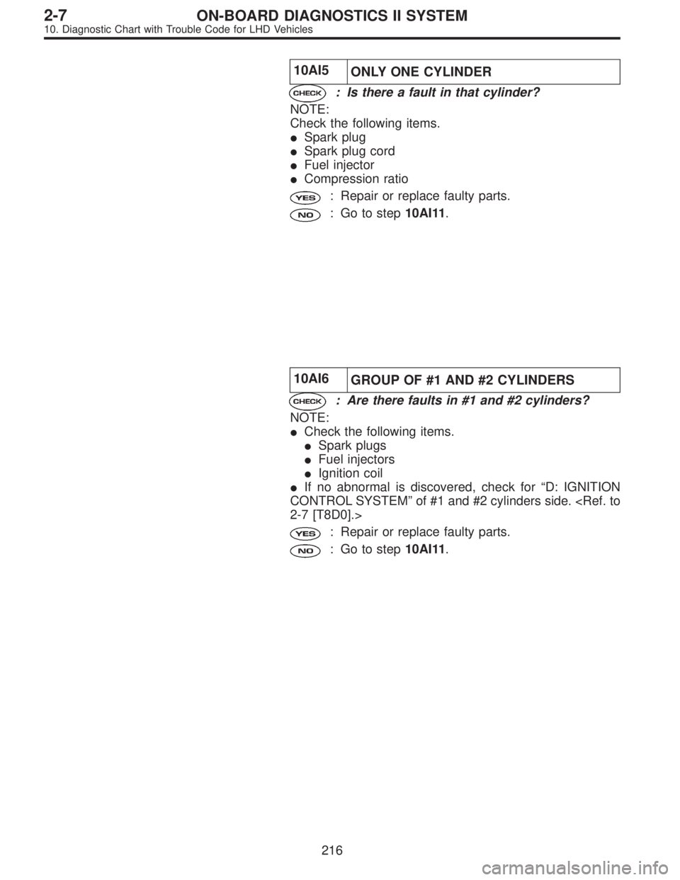
10AI5
ONLY ONE CYLINDER
: Is there a fault in that cylinder?
NOTE:
Check the following items.
�Spark plug
�Spark plug cord
�Fuel injector
�Compression ratio
: Repair or replace faulty parts.
: Go to step10AI11.
10AI6
GROUP OF #1 AND #2 CYLINDERS
: Are there faults in #1 and #2 cylinders?
NOTE:
�Check the following items.
�Spark plugs
�Fuel injectors
�Ignition coil
�If no abnormal is discovered, check for“D: IGNITION
CONTROL SYSTEM”of #1 and #2 cylinders side.
2-7 [T8D0].>
: Repair or replace faulty parts.
: Go to step10AI11.
216
2-7ON-BOARD DIAGNOSTICS II SYSTEM
10. Diagnostic Chart with Trouble Code for LHD Vehicles
![SUBARU LEGACY 1997 Service Repair Manual 2. CHECKING THE HYDRAULIC UNIT TCS
OPERATION WITH BRAKE TESTER
1) Prepare for operating TCS sequence control. <Ref. to
4-4 [W20F1] step 1 or 4-4 [W20F2] step 1.>
B4M0638
2) Set the front wheels on the](/manual-img/17/57434/w960_57434-1397.png "SUBARU LEGACY 1997 Service Repair Manual 2. CHECKING THE HYDRAULIC UNIT TCS
OPERATION WITH BRAKE TESTER
1) Prepare for operating TCS sequence control. <Ref. to
4-4 [W20F1] step 1 or 4-4 [W20F2] step 1.>
B4M0638
2) Set the front wheels on the")