Page 2459 of 3342
 57
F01 Battery voltage VB V Battery voltage")
B: LIST OF OUTPUT MODES
1. FUNCTION MODE
Mode Contents Abbr. Unit Contents of display Page
F00 Mode display——AT or EGI mode (when monitor is connected.) 57
F01 Battery voltage VB V Battery voltage applied to control unit. 57
F02 Vehicle speed sensor 1 VSP1 m/h Vehicle speed (miles/h) sent from vehicle speed sensor 1. 58
F03 Vehicle speed sensor 1 VSP1 km/h Vehicle speed (km/h) sent from vehicle speed sensor 1. 58
F04 Vehicle speed sensor 2 VSP2 m/h Vehicle speed (miles/h) sent from vehicle speed sensor 2. 58
F05 Vehicle speed sensor 2 VSP2 km/h Vehicle speed (km/h) sent from vehicle speed sensor 2. 58
F06 Engine speed EREV rpm Engine speed sent from ECM. 59
F07 ATF temperature sensor ATFT°F ATF temperature (°F) sent from ATF temperature sensor. 59
F08 ATF temperature sensor ATFT°C ATF temperature (°C) sent from ATF temperature sensor. 59
F09 Throttle position sensor THV V Voltage sent from throttle position sensor. 60
F10 Gear position GEAR—Transmission gear position 60
F11 Line pressure duty PLDTY % Duty ratio flowing through duty solenoid A. 61
F12 Lock-up duty LUDTY % Duty ratio flowing through duty solenoid B. 62
F13 AWD duty 4WDTY % Duty ratio flowing through duty solenoid C. 63
F14Throttle position sensor
power supplyTHVCC V Power supply voltage to throttle position sensor 64
F15 Mass air flow signal AFM V Output voltage from air flow sensor 64
55
3-2AUTOMATIC TRANSMISSION AND DIFFERENTIAL
8. Diagnostic Chart with Select Monitor
Page 2467 of 3342
G3M0733
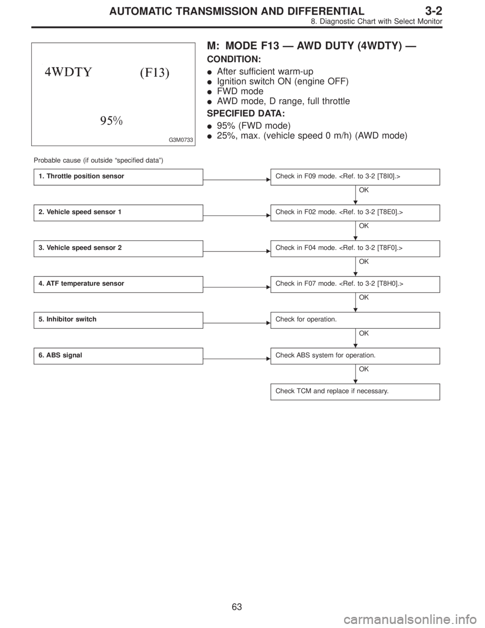
M: MODE F13—AWD DUTY (4WDTY)—
CONDITION:
�After sufficient warm-up
�Ignition switch ON (engine OFF)
�FWD mode
�AWD mode, D range, full throttle
SPECIFIED DATA:
�95% (FWD mode)
�25%, max. (vehicle speed 0 m/h) (AWD mode)
Probable cause (if outside“specified data”)
1. Throttle position sensor
�Check in F09 mode.
OK
2. Vehicle speed sensor 1
�Check in F02 mode.
OK
3. Vehicle speed sensor 2
�Check in F04 mode.
OK
4. ATF temperature sensor
�Check in F07 mode.
OK
5. Inhibitor switch
�Check for operation.
OK
6. ABS signal
�Check ABS system for operation.
OK
Check TCM and replace if necessary.
�
�
�
�
�
�
63
3-2AUTOMATIC TRANSMISSION AND DIFFERENTIAL
8. Diagnostic Chart with Select Monitor
Page 2711 of 3342
WIRING DIAGRAM:
B4M1050
8N1CHECK ALL FOUR WHEELS FOR FREE
TURNING.
: Have the wheels been turned freely such as
when the vehicle is lifted up, or operated on
a rolling road?
: The ABS is normal. Erase the trouble code.
: Go to step8N2.
B4M0910A
8N2
CHECK SPECIFICATIONS OF ABSCM.
Check specifications of the plate attached to the ABSCM.
: Is an ABSCM for 4WD model installed on a
FWD model?
CAUTION:
Be sure to turn ignition switch to OFF when removing
ABSCM.
: Replace ABSCM.
: Go to step8N3.
106
4-4cBRAKES [ABS 5.3 TYPE]
8. Diagnostics Chart with Trouble Code
Page 2857 of 3342
 Press
F,
0and
0on the select monitor.
2) Read the select monitor display.
: Is an ABSCM for 4WD model installed on a
FWD model?
: Re")
B4M0921
10AH1CHECK SPECIFICATIONS OF ABSCM
USING SELECT MONITOR.
1) Press
F,
0and
0on the select monitor.
2) Read the select monitor display.
: Is an ABSCM for 4WD model installed on a
FWD model?
: Replace ABSCM.
: Go to step10AH2.
B4M0927
10AH2CHECK OUTPUT OF G SENSOR USING
SELECT MONITOR.
1) Press
F,
1and
0on the select monitor.
2) Read the select monitor display.
: Is the indicated reading 2.3±0.2 V when the
G sensor is in horizontal position?
: Go to step10AH3.
: Go to step10AH5.
10AH3CHECK POOR CONTACT IN CONNEC-
TOR BETWEEN ABSCM AND G SENSOR.
: Is there poor contact in connector between
ABSCM and G sensor?
: Repair connector.
: Go to step10AH4.
10AH4
CHECK ABSCM.
1) Connect all connectors.
2) Erase the memory.
3) Perform inspection mode.
4) Read out the trouble code.
: Is the same trouble code as in the current
diagnosis still being output?
: Replace ABSCM.
: Go to next.
: Are other trouble codes being output?
: Proceed with the diagnosis corresponding to the
trouble code.
: A temporary poor contact.
252
4-4cBRAKES [ABS 5.3 TYPE]
10. Diagnostics Chart with Select Monitor
Page 3041 of 3342
![SUBARU LEGACY 1997 Service Repair Manual H4M1117
10AG1CHECK SPECIFICATIONS OF
ABSCM&H/U USING SELECT MONITOR.
1) Press [F], [0] and [0] on the select monitor.
2) Read the select monitor display.
: Is an ABSCM&H/U for 4WD model installed
on a](/manual-img/17/57434/w960_57434-3040.png "SUBARU LEGACY 1997 Service Repair Manual H4M1117
10AG1CHECK SPECIFICATIONS OF
ABSCM&H/U USING SELECT MONITOR.
1) Press [F], [0] and [0] on the select monitor.
2) Read the select monitor display.
: Is an ABSCM&H/U for 4WD model installed
on a")
H4M1117
10AG1CHECK SPECIFICATIONS OF
ABSCM&H/U USING SELECT MONITOR.
1) Press [F], [0] and [0] on the select monitor.
2) Read the select monitor display.
: Is an ABSCM&H/U for 4WD model installed
on a FWD model?
: Replace ABSCM&H/U.
: Go to step10AG2.
B4M0927
10AG2CHECK OUTPUT OF G SENSOR USING
SELECT MONITOR.
1) Press [F], [1] and [0] on the select monitor.
2) Read the select monitor display.
: Is the indicated reading between 2.1 and 2.5
V when the G sensor is in horizontal posi-
tion?
: Go to step10AG3.
: Go to step10AG6.
10AG3CHECK POOR CONTACT IN CONNEC-
TORS.
: Is there poor contact in connector between
ABSCM&H/U and G sensor?
WORD [T3C1].>
: Repair connector.
: Go to step10AG4.
10AG4
CHECK ABSCM&H/U.
1) Connect all connectors.
2) Erase the memory.
3) Perform inspection mode.
4) Read out the trouble code.
: Is the same trouble code as in the current
diagnosis still being output?
: Replace ABSCM&H/U.
: Go to step10AG5.
10AG5CHECK ANY OTHER TROUBLE CODES
APPEARANCE.
: Are other trouble codes being output?
: Proceed with the diagnosis corresponding to the
trouble code.
: A temporary poor contact.
165
4-4dBRAKES [ABS 5.3i TYPE]
10. Diagnostics Chart with Select Monitor