Page 374 of 2053
M161 ENGINE MECHANICAL 1B2 -- 81
D AEW OO M Y_2000
CRANKSHAFT SPROCKET
Preceding Work: Removal of oil pan
Removal of tensioning rail
Removal of crank case guide rail
1 Oil Pump Chain Tensioner
2 Oil Pump Chain Bushing
3 Oil Pump Chain Spring
4 Crankshaft Sprocket
5Key6 Bolt (M8 x 20, 1 piece) / Washer
29-- 35 NSm (21-- 26 lb-ft) ...................
7 Oil Pump Sprocket
8OilPump
9 Oil Pump Roller Chain
10 Timing Chain
Page 375 of 2053

1B2 -- 82 M161 ENGINE MECHANICAL
D AEW OO M Y_2000
Tools Required
615 589 01 33 00 Crankshaft Sprocket Puller
Removal & Installation Procedure
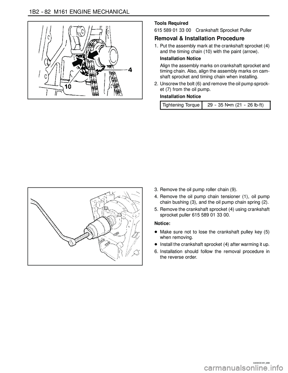
1. Put the assembly mark at the crankshaft sprocket (4)
and the timing chain (10) with the paint (arrow).
Installation Notice
Align the assembly marks on crankshaft sprocket and
timing chain. Also, align the assembly marks on cam-
shaft sprocket and timing chain when installing.
2. Unscrew the bolt (6) and remove the oil pump sprock-
et (7) from the oil pump.
Installation Notice
Tightening Torque
29 -- 35 NSm (21 -- 26 lb-ft)
3. Remove the oil pump roller chain (9).
4. Remove the oil pump chain tensioner (1), oil pump
chain bushing (3), and the oil pump chain spring (2).
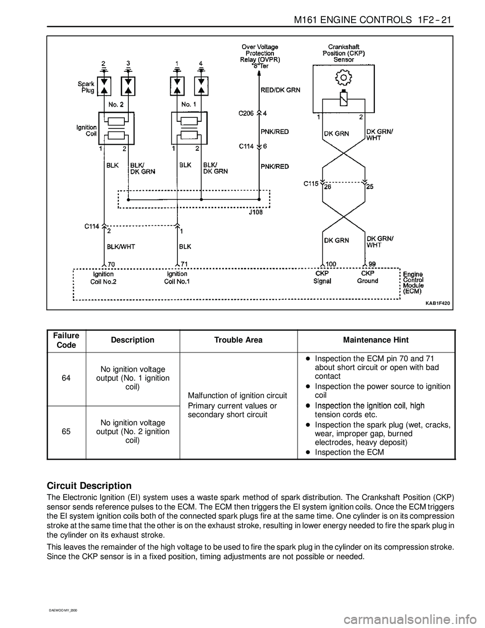
5. Remove the crankshaft sprocket (4) using crankshaft
sprocketpuller615589013300.
Notice:
DMake sure not to lose the crankshaft pulley key (5)
when removing.
DInstall the crankshaft sprocket (4) after warming it up.
6. Installation should follow the removal procedure in
the reverse order.
Page 386 of 2053
1B2 -- 98 M161 ENGINE MECHANICAL
D AEW OO M Y_2000
OIL NON-- RETURN VALVE
Preceding Work: Removal of timing gear case cover
1 Oil Non-- return Valve
Functions
The non -- return valve prevents the oil in the chain ten-
sioner from drying up. In other words, it stops oil-- return-
ing in order to prevent the oil in the chain tensioner from
getting dry. As a result, the chain tensioner can be acti-
vated with oil in itself.
Replacement Procedure
1. Remove the non--return valve using a pliers.
2. Insert new non-- return valve with hand.
Page 438 of 2053

1F2 -- 18 M161 ENGINE CONTROLS
D AEW OO M Y_2000
IGNITION SYSTEM
This ignition system does not use a conventional distributor andcoil. It uses a crankshaft position sensor input to the
Engine Control Module (ECM). The ECM then determines Electronic Spark Timing (EST) and triggers the electronic
ignition system ignition coil.
This type of distributorless ignition system uses a‘‘waste spark” method of spark distribution. Each cylinder is paired
with the cylinder that is opposite it (2 -- 3 or 1 -- 4). The spark occurs simultaneously in the cylinder coming up on the
compression stroke and in the cylinder coming up on the exhaust stroke. The cylinder on the exhaust stroke requires
very little of the available energy to fire the spark plug. The remaining energy is available to the spark plug in the cylin-
der on the compression stroke.
These systems use the EST signal from the ECM to control the EST. The ECM uses the following information:
DEngine load (mass air flow sensor).
DEngine temperature.
DIntake air temperature.
DCrankshaft position.
DEngine speed (rpm).
YAA1F910
Page 441 of 2053

M161 ENGINE CONTROLS 1F2 -- 21
D AEW OO M Y_2000
KAB1F420
Failure
CodeDescriptionTrouble AreaMaintenance Hint
64
No ignition voltage
output (No. 1 ignition
coil)
Malfunction of ignition circuit
Primarycurrentvaluesor
DInspection the ECM pin 70 and 71
about short circuit or open with bad
contact
DInspection the power source to ignition
coil
DInspectiontheignitioncoilhigh
65
No ignition voltage
output (No. 2 ignition
coil)
Primary currentvalues or
secondary short circuitDInspectiontheignition coil,high
tension cords etc.
DInspection the spark plug (wet, cracks,
wear, improper gap, burned
electrodes, heavy deposit)
DInspection the ECM
Circuit Description
The Electronic Ignition (EI) system uses a waste spark method of spark distribution. The Crankshaft Position (CKP)
sensor sends reference pulses to the ECM. The ECM then triggers the EI system ignition coils. Once the ECM triggers
the EI system ignition coils both of the connected spark plugs fire at the same time. One cylinder is on its compression
stroke at the same time that the other is on the exhaust stroke, resulting in lower energy needed to fire the spark plug in
the cylinder on its exhaust stroke.
This leaves the remainder of the high voltage to be used to fire the spark plug in the cylinder on its compression stroke.
Since the CKP sensor is in a fixed position, timing adjustments are not possible or needed.
Page 450 of 2053
1F2 -- 32 M161 ENGINE CONTROLS
D AEW OO M Y_2000
KNOCK SENSOR (KS)
YAA1F320
The Knock Sensor (KS) detects abnormal knocking in the engine. The two KS are mounted in the engine block near
the cylinders. The sensors produce an output voltage which increases with the severity of the knock. This signal is sent
to the Engine Control Module (ECM) via a shielded cable. The ECM then adjusts the ignition timing to reduce the spark
knock.
Page 451 of 2053

M161 ENGINE CONTROLS 1F2 -- 33
D AEW OO M Y_2000
KAB1F440
Failure
CodeDescriptionTrouble AreaMaintenance Hint
56No. 1 knock sensor
signal failure
When recognition in more
than control gain threshold at
normal operational condition
of other system during over
75 and 3,000 rpm running
area (cylinder 1, 2, 3, 4)DInspection the ECM pin 118, 117 about
short circuit or open with bad contact
DInspection the KS 1 malfunction
DInspection the ECM
Circuit Description
The KS system is used to detect engine detonation, allowing the ECM to retard the ignition control spark timing based
on the KS signal being received. The KS signal’s amplitude and frequency depend upon the amount of knock being
experienced. The ECM monitors the KS signal and can diagnose the KS sensor and circuitry.
Knock Sensor Resistance Inspection
1. Disconnect the coupling from ECM while the ignition switch is in “OFF” position.
2. Measure the resistance between the coupling terminal pin No. 118 and No. 117 using a multimeter.
Specified Value
>10 MΩ
Notice:Replace the KS if the measured values is out of the specified values. Check the connector and wire connec-
tion between ECM and the KS if the measured values are normal.
Page 453 of 2053
M161 ENGINE CONTROLS 1F2 -- 35
D AEW OO M Y_2000
KAB1F450
Failure
CodeDescriptionTrouble AreaMaintenance Hint
68Random / Multiple
Misfire
When detection misfire of
multiple cylinder for source of
over the emission threshold or
catalyst damage
DInspection the ignition system
DInspection the injection system
DInspection the fuel pressure
DInspection the compression pressure
DInspection the valve timing or
clearance
DInspection the air flow sensor
DInspection the crankshaft position
sensor and air gap
DInspection the engine wiring system
DInspection the Engine Control Module
(ECM)
Circuit Description
The ECM monitors the crankshaft and camshaft positions to detect if the engine is misfiring. The ECM looks for a quick
drop in crankshaft speed. Misfire multiple cylinder is monitored by engine roughness measuring. The actual roughness
value is compared with the actual (emission and catalyst damage) threshold.