Page 1728 of 2053
INSTRUMENTATION, DRIVER INFORMATION 9E-11
SSANGYONG MY2002
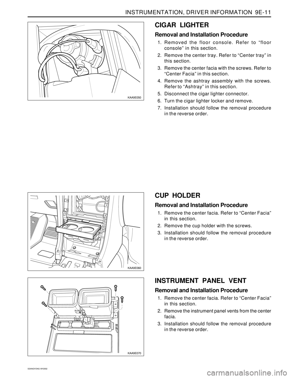
KAA9E060
KAA9E070
CUP HOLDER
Removal and Installation Procedure
1. Remove the center facia. Refer to “Center Facia”
in this section.
2. Remove the cup holder with the screws.
3. Installation should follow the removal procedure
in the reverse order.
KAA9E050
CIGAR LIGHTER
Removal and Installation Procedure
1. Removed the floor console. Refer to “floor
console” in this section.
2. Remove the center tray. Refer to “Center tray” in
this section.
3. Remove the center facia with the screws. Refer to
“Center Facia” in this section.
4. Remove the ashtray assembly with the screws.
Refer to “Ashtray” in this section.
5. Disconnect the cigar lighter connector.
6. Turn the cigar lighter locker and remove.
7. Installation should follow the removal procedure
in the reverse order.
INSTRUMENT PANEL VENT
Removal and Installation Procedure
1. Remove the center facia. Refer to “Center Facia”
in this section.
2. Remove the instrument panel vents from the center
facia.
3. Installation should follow the removal procedure
in the reverse order.
Page 1731 of 2053
SSANGYONG MY2002
9E-14 INSTRUMENTATION, DRIVER INFORMATION
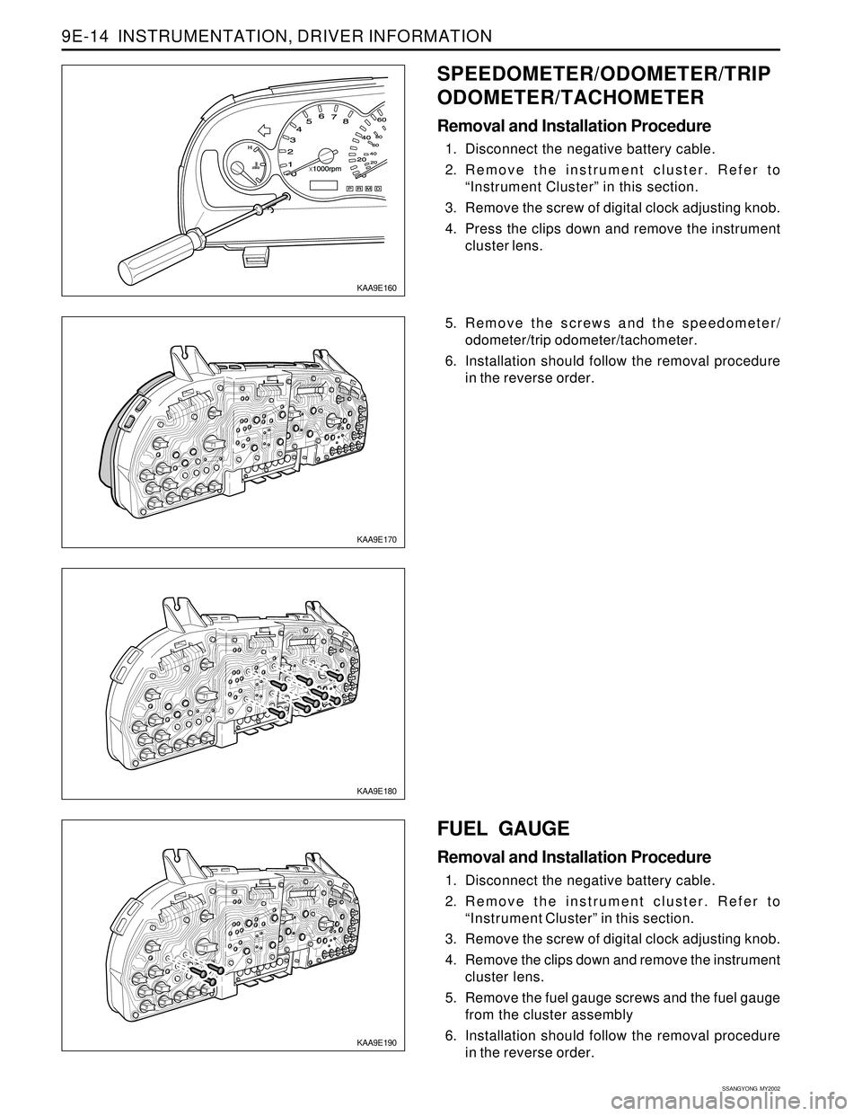
KAA9E170
KAA9E180
KAA9E190
5. Remove the screws and the speedometer/
odometer/trip odometer/tachometer.
6. Installation should follow the removal procedure
in the reverse order.
FUEL GAUGE
Removal and Installation Procedure
1. Disconnect the negative battery cable.
2. Remove the instrument cluster. Refer to
“Instrument Cluster” in this section.
3. Remove the screw of digital clock adjusting knob.
4. Remove the clips down and remove the instrument
cluster lens.
5. Remove the fuel gauge screws and the fuel gauge
from the cluster assembly
6. Installation should follow the removal procedure
in the reverse order.
KAA9E160
SPEEDOMETER/ODOMETER/TRIP
ODOMETER/TACHOMETER
Removal and Installation Procedure
1. Disconnect the negative battery cable.
2. Remove the instrument cluster. Refer to
“Instrument Cluster” in this section.
3. Remove the screw of digital clock adjusting knob.
4. Press the clips down and remove the instrument
cluster lens.
Page 1732 of 2053
INSTRUMENTATION, DRIVER INFORMATION 9E-15
SSANGYONG MY2002
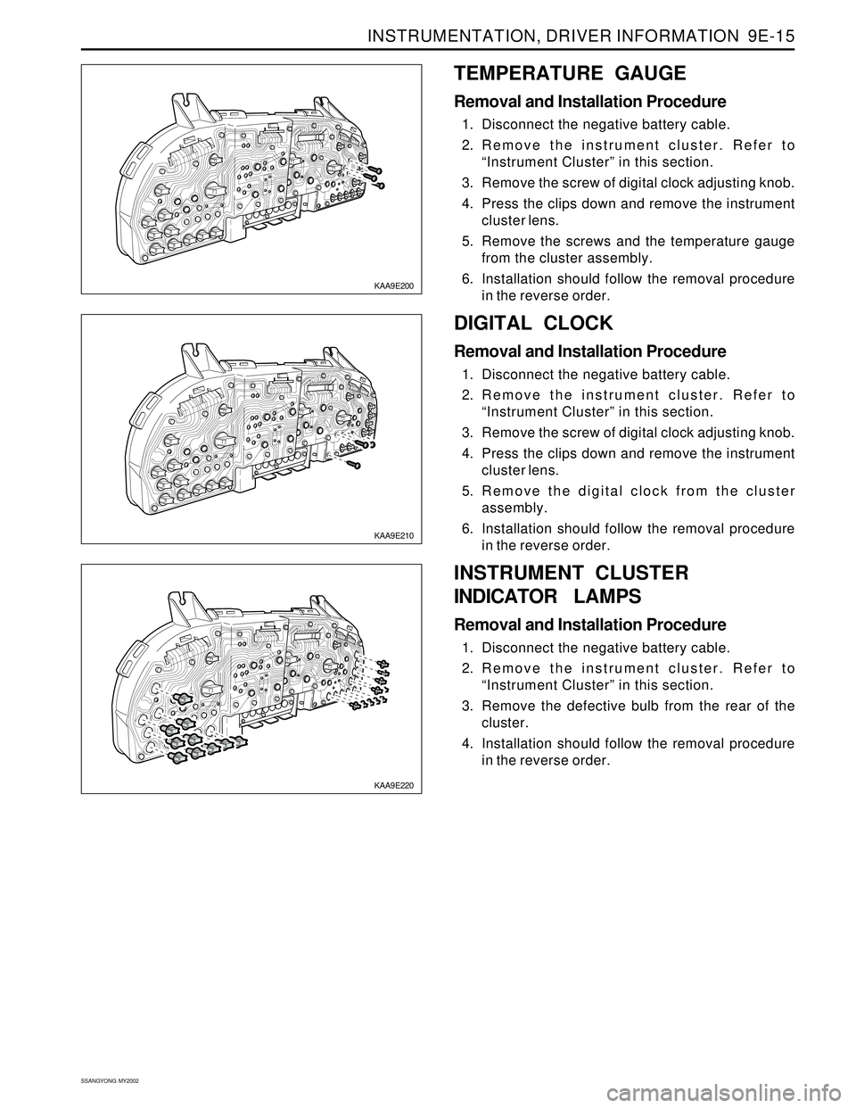
KAA9E210
KAA9E220
DIGITAL CLOCK
Removal and Installation Procedure
1. Disconnect the negative battery cable.
2. Remove the instrument cluster. Refer to
“Instrument Cluster” in this section.
3. Remove the screw of digital clock adjusting knob.
4. Press the clips down and remove the instrument
cluster lens.
5. Remove the digital clock from the cluster
assembly.
6. Installation should follow the removal procedure
in the reverse order.
KAA9E200
TEMPERATURE GAUGE
Removal and Installation Procedure
1. Disconnect the negative battery cable.
2. Remove the instrument cluster. Refer to
“Instrument Cluster” in this section.
3. Remove the screw of digital clock adjusting knob.
4. Press the clips down and remove the instrument
cluster lens.
5. Remove the screws and the temperature gauge
from the cluster assembly.
6. Installation should follow the removal procedure
in the reverse order.
INSTRUMENT CLUSTER
INDICATOR LAMPS
Removal and Installation Procedure
1. Disconnect the negative battery cable.
2. Remove the instrument cluster. Refer to
“Instrument Cluster” in this section.
3. Remove the defective bulb from the rear of the
cluster.
4. Installation should follow the removal procedure
in the reverse order.
Page 1742 of 2053
INSTRUMENTATION, DRIVER INFORMATION 9E-25
SSANGYONG MY2002
DIGITAL CLOCK, WARNING CLUSTER ILLUMINATION
KAA9E370
Page 1744 of 2053
Description and Operation.................................. 9F-2
Speakers............................................................ 9F-2
Mast Antenna..................................................... 9F-2
Tape Player and Cassette Care........................... 9F-2
Components Locator ........................................... 9F-3
Audio System..................................................... 9F-3
Repair Instructions............................................... 9F-4
SECTION 9F
AUDIO SYSTEM
CAUTION: Disconnect the negative battery cable before removing or installing any electrical unit or when a
tool or equipment could easily come in contact with exposed electrical terminals. Disconnecting this cable
will help prevent personal injury and damage to the vehicle. The ignition must also be in LOCK unless
otherwise noted.
TABLE OF CONTENTS
On-Vehicle Service Unit Repair............................... 9F-4
Stereo Cassette AM/FM Radio............................ 9F-4
Front Door Speakers........................................... 9F-4
Rear Speakers.................................................... 9F-5
Mast Antenna..................................................... 9F-5
Schematic and Routing Diagram....................... 9F-7
Audio System Circuit .......................................... 9F-7
Page 1750 of 2053
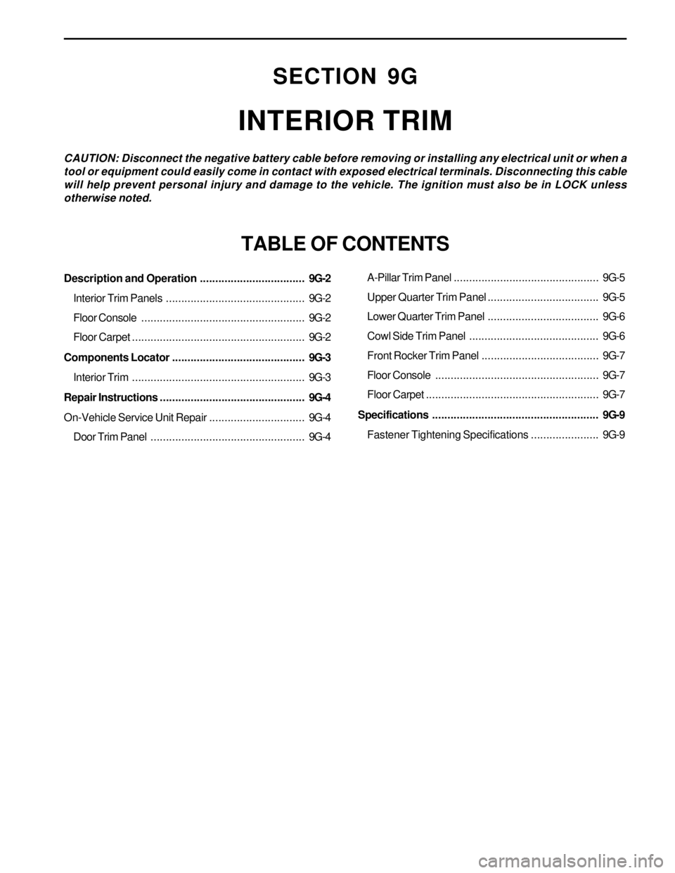
Description and Operation..................................9G-2
Interior Trim Panels.............................................9G-2
Floor Console.....................................................9G-2
Floor Carpet........................................................9G-2
Components Locator ...........................................9G-3
Interior Trim........................................................9G-3
Repair Instructions...............................................9G-4
On-Vehicle Service Unit Repair...............................9G-4
Door Trim Panel..................................................9G-4
SECTION 9G
INTERIOR TRIM
CAUTION: Disconnect the negative battery cable before removing or installing any electrical unit or when a
tool or equipment could easily come in contact with exposed electrical terminals. Disconnecting this cable
will help prevent personal injury and damage to the vehicle. The ignition must also be in LOCK unless
otherwise noted.
TABLE OF CONTENTS
A-Pillar Trim Panel...............................................9G-5
Upper Quarter Trim Panel....................................9G-5
Lower Quarter Trim Panel....................................9G-6
Cowl Side Trim Panel ..........................................9G-6
Front Rocker Trim Panel......................................9G-7
Floor Console.....................................................9G-7
Floor Carpet........................................................9G-7
Specifications......................................................9G-9
Fastener Tightening Specifications......................9G-9
Page 1759 of 2053

SECTION 9H
SEATS
TABLE OF CONTENTS
Components Locator............................................9H-2
Seats ...................................................................9H-2
Repair Instructions................................................9H-3
On-Vehicle Service Unit Repair................................9H-3
Front Seat............................................................9H-3
Front Seat Cushion..............................................9H-3
Front Seatback....................................................9H-4
Front Seat Guide Rail ...........................................9H-4
Front Seat Recliner Lever.....................................9H-5
Front Seat Trim....................................................9H-5
Head Restraint.....................................................9H-5Walk In Device....................................................9H-6
Front Seat Armrest...............................................9H-6
Rear Seat Armrest ...............................................9H-6
Rear Seat............................................................9H-7
50/50 Split Rear Seat Cushion Hinge....................9H-7
50/50 Split Rear Seat Cushion Lock Striker...........9H-8
Child Seat Anchorage ..........................................9H-8
Specifications.......................................................9H-9
Fastener Tightening Specifications.......................9H-9
Schematic and Routing Diagram......................9H-10
Seat Heater.......................................................9H-10
Page 1766 of 2053
SSANGYONG MY2002
9H-8 SEATS
50/50 SPLIT REAR SEAT CUSHION
LOCK STRIKER
Removal and Installation Procedure
1. Remove the bolts and rear seat cushion lock
striker.
Installation Notice
Dissimilar metals in direct contact with each
other may corrode rapidly. Make sure to use
the correct fasteners to prevent premature
corrosion.
2. Installation should follow the removal procedure
in the reverse order.
KAA9H200
2. Remove the child seat anchorage bolt.
Installation Notice
Dissimilar metals in direct contact with each
other may corrode rapidly. Make sure to use
the correct fasteners to prevent premature
corrosion.
3. Installation should follow the removal procedure
in the reverse order.
KAA9H190
CHILD SEAT ANCHORAGE
Removal and Installation Procedure
1. Remove the child seat anchorage cover.
Tightening Torque34.3 - 53.9 Nm
(25 - 39 lb-ft)
KAA9H170
Tightening Torque 19 Nm (14 lb-ft)