1997 SSANGYONG KORANDO check engine
[x] Cancel search: check enginePage 1781 of 2053

SQUEAKS AND RATTLES 9K-3
SSANGYONG MY2002
Check for a lack of lubrication of the door hinge pins.ChecksActionOperate the doors and listen for squeaks.
Lubricate the door hinge pins with light oil and coat
with lithium grease.
Squeak Coming From Console When Shifting Manual Transaxle
(Condition Occurs In Cold Weather with a Cold Engine)
Check the manual transaxle control lever lower boot.ChecksActionMove the control lever between gears and listen for
squeaks.
Remove the floor console and replace the lower shift
boot or apply talcum powder to the lower shift boot.
Squeak When Operating Doors
Check for vibration of the fuse box cover against the
instrument panel side trim.ChecksActionTap on thecoverwith a fingerandlisten fora buzz.
Apply 6.35 mm (0.250 inch) by 25.4 mm (1.00 inch)
felt pads to the side trim where the cover makes
contact.
Squeak Coming From Instrument Cluster Trim Plate
Check for rubbing of the cluster trim plate on the
instrument panel.ChecksActionTest drive the vehicle in order to verify this condi-
tion.
Remove the instrument cluster trim plate and install
felt tape to the edges.
Buzz From the Left Side of Instrument Panel
Check the door lock solenoid.
Check for rattling electrical connectors inside the door
trim panel.ChecksActionRemove the door trim panel and check if the sole-
noid is loose.
Tighten the solenoid bolts.
Tap on the trim panel and listen for a rattle.
Remove the trim panel and wrap foam padding
around the connectors as required.
Rattle Coming From Door
Page 1803 of 2053
SECTION 9N
FRAME AND UNDERBODY
TABLE OF CONTENTS
Specifications.......................................................9N-2
Fastener Tightening Specifications.......................9N-2
Underbody Dimensions.......................................9N-3
Maintenance and Repair.....................................9N-7
On-Vehicle Service.................................................9N-7
Alignment Checking............................................9N-7Floor Pan Insulators.............................................9N-7
Engine Under Covers ...........................................9N-8
General Description and System Operation........9N-9
General Body Construction..................................9N-9
Engine Under Covers ...........................................9N-9
Page 1809 of 2053
FRAME AND UNDERBODY 9N-7
SSANGYONG MY2002
ON-VEHICLE SERVICE
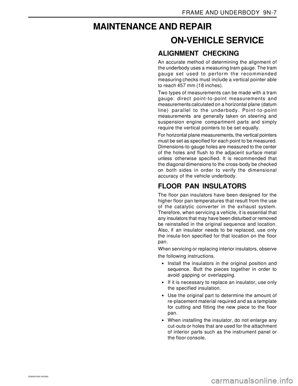
ALIGNMENT CHECKING
An accurate method of determining the alignment of
the underbody uses a measuring tram gauge. The tram
gauge set used to perform the recommended
measuring checks must include a vertical pointer able
to reach 457 mm (18 inches).
Two types of measurements can be made with a tram
gauge: direct point-to-point measurements and
measurements calculated on a horizontal plane (datum
line) parallel to the underbody. Point-to-point
measurements are generally taken on steering and
suspension engine compartment parts and simply
require the vertical pointers to be set equally.
For horizontal plane measurements, the vertical pointers
must be set as specified for each point to be measured.
Dimensions-to-gauge holes are measured to the center
of the holes and flush to the adjacent surface metal
unless otherwise specified. It is recommended that
the diagonal dimensions to the cross-body be checked
on both sides in order to verify the dimensional
accuracy of the vehicle underbody.
FLOOR PAN INSULATORS
The floor pan insulators have been designed for the
higher floor pan temperatures that result from the use
of the catalytic converter in the exhaust system.
Therefore, when servicing a vehicle, it is essential that
any insulators that may have been disturbed or removed
be reinstalled in the original sequence and location.
Also, if an insulator needs to be replaced, use only
the insula-tion specified for that location on the floor
pan.
When servicing or replacing interior insulators, observe
the following instructions.
•Install the insulators in the original position and
sequence. Butt the pieces together in order to
avoid gapping or overlapping.
If it is necessary to replace an insulator, use only
the specified insulation.
Use the original part to determine the amount of
re-placement material required and as a template
for cutting and fitting the new piece to the floor
pan.
When installing the insulator, do not enlarge any
cut-outs or holes that are used for the attachment
of interior parts such as the instrument panel or
the floor console.
MAINTENANCE AND REPAIR
Page 1858 of 2053
SSANGYONG MY2002
9T2-2 IMMOBILIZER SYSTEM
DESCRIPTION AND OPERATION
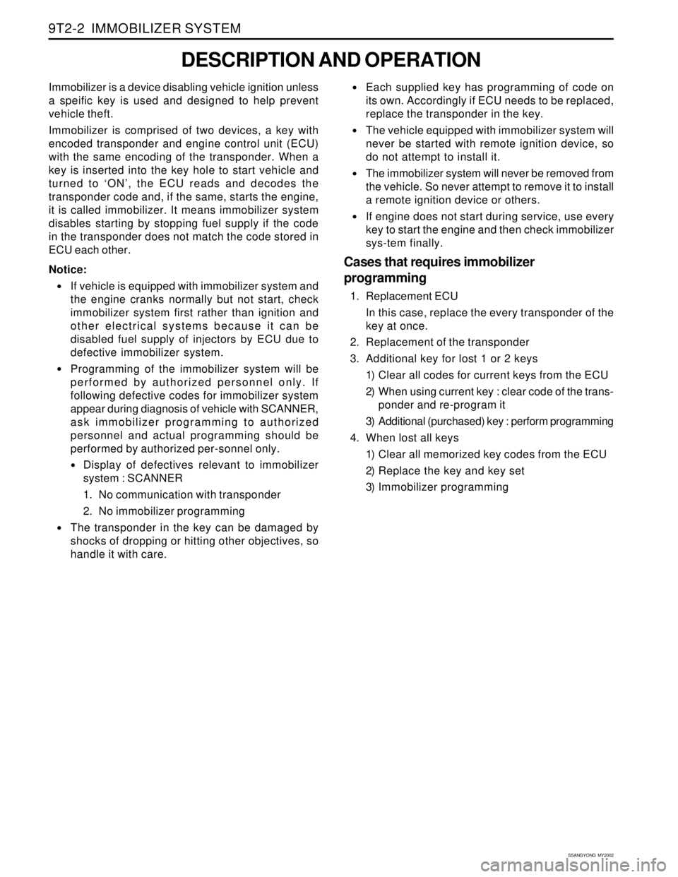
Immobilizer is a device disabling vehicle ignition unless
a speific key is used and designed to help prevent
vehicle theft.
Immobilizer is comprised of two devices, a key with
encoded transponder and engine control unit (ECU)
with the same encoding of the transponder. When a
key is inserted into the key hole to start vehicle and
turned to ‘ON’, the ECU reads and decodes the
transponder code and, if the same, starts the engine,
it is called immobilizer. It means immobilizer system
disables starting by stopping fuel supply if the code
in the transponder does not match the code stored in
ECU each other.
Notice:
If vehicle is equipped with immobilizer system and
the engine cranks normally but not start, check
immobilizer system first rather than ignition and
other electrical systems because it can be
disabled fuel supply of injectors by ECU due to
defective immobilizer system.
Programming of the immobilizer system will be
performed by authorized personnel only. If
following defective codes for immobilizer system
appear during diagnosis of vehicle with SCANNER,
ask immobilizer programming to authorized
personnel and actual programming should be
performed by authorized per-sonnel only.
Display of defectives relevant to immobilizer
system : SCANNER
1. No communication with transponder
2. No immobilizer programming
The transponder in the key can be damaged by
shocks of dropping or hitting other objectives, so
handle it with care.
Each supplied key has programming of code on
its own. Accordingly if ECU needs to be replaced,
replace the transponder in the key.
The vehicle equipped with immobilizer system will
never be started with remote ignition device, so
do not attempt to install it.
The immobilizer system will never be removed from
the vehicle. So never attempt to remove it to install
a remote ignition device or others.
If engine does not start during service, use every
key to start the engine and then check immobilizer
sys-tem finally.
Cases that requires immobilizer
programming
1. Replacement ECU
In this case, replace the every transponder of the
key at once.
2. Replacement of the transponder
3. Additional key for lost 1 or 2 keys
1) Clear all codes for current keys from the ECU
2) When using current key : clear code of the trans-
ponder and re-program it
3) Additional (purchased) key : perform programming
4. When lost all keys
1) Clear all memorized key codes from the ECU
2) Replace the key and key set
3) Immobilizer programming
Page 1864 of 2053
HOW TO USE ELECTRICAL WIRING DIAGRAM HOW TO USE ELECTRICAL WIRING DIAGRAM HOW TO USE ELECTRICAL WIRING DIAGRAM HOW TO USE ELECTRICAL WIRING DIAGRAM
HOW TO USE ELECTRICAL WIRING DIAGRAM
1-3 1-31-3 1-3
1-3
Connector
Diode
Fuse in engine room fuse & relay box
Fuse in passenger room fuse box
GroundJoint - Inline wire connected pointSplice pack(Junction connector) C CC C
C
D DD D
D
Ef EfEf Ef
Ef
F FF F
F
G GG G
G
J JJ J
J
S SS S
S
2. 2.2. 2.
2.
CIRCUIT IDENTIFICA CIRCUIT IDENTIFICACIRCUIT IDENTIFICA CIRCUIT IDENTIFICA
CIRCUIT IDENTIFICA
TION SYMBOL TION SYMBOLTION SYMBOL TION SYMBOL
TION SYMBOL
3. 3.3. 3.
3.
FUNCTION OF PO FUNCTION OF POFUNCTION OF PO FUNCTION OF PO
FUNCTION OF PO
WER SUPPL WER SUPPLWER SUPPL WER SUPPL
WER SUPPL
Y LINE (NUMBER) Y LINE (NUMBER)Y LINE (NUMBER) Y LINE (NUMBER)
Y LINE (NUMBER)
IDENTIFICATION IDENTIFICATIONIDENTIFICATION IDENTIFICATION
IDENTIFICATION
SYMBOL SYMBOLSYMBOL SYMBOL
SYMBOLMEANING MEANINGMEANING MEANING
MEANINGPower supply No Power supply NoPower supply No Power supply No
Power supply No
Power supply condition Power supply conditionPower supply condition Power supply condition
Power supply condition
Battery Voltage(B+) supply in Ignition Switch "ON" and "ST" (IGN 1)Battery Voltage(B+) supply in Ignition Switch "ON" (IGN 2)
Battery Voltage(B+) supply in Ignition Switch "ON" and "ACC"
Battery Voltage(B+) supply directly regardless of Ignition Switch
Ground connected to battery(–)Battery Voltage(B+) supply in Head Lamp Switch 1st and 2nd step(Illumination circuit) 15 1515 15
15
15A 15A15A 15A
15A
15C 15C15C 15C
15C
30 3030 30
30
31 3131 31
31
58 5858 58
58
Abbreviation AbbreviationAbbreviation Abbreviation
Abbreviation
Color ColorColor Color
Color
Brown
Green
Violet
Pink
White
Orange
Light Green Br BrBr Br
Br
G GG G
G
V VV V
V
P PP P
P
W WW W
W
Or OrOr Or
Or
Lg LgLg Lg
Lg
Abbreviation AbbreviationAbbreviation Abbreviation
Abbreviation
Color ColorColor Color
Color
Sky Blue
Red
Blue
Yellow
Gray
Black Sb SbSb Sb
Sb
R RR R
R
L LL L
L
Y YY Y
Y
Gr GrGr Gr
Gr
B BB B
B
4. 4.4. 4.
4.
WIRING HARNESS COLOR IDENTIFICA WIRING HARNESS COLOR IDENTIFICAWIRING HARNESS COLOR IDENTIFICA WIRING HARNESS COLOR IDENTIFICA
WIRING HARNESS COLOR IDENTIFICA
TION TIONTION TION
TION5. 5.5. 5.
5.
HO HOHO HO
HO
W W W W
W
T TT T
T
O CHECK O CHECK O CHECK O CHECK
O CHECK
TERMINAL NUMBER OF CONNECT TERMINAL NUMBER OF CONNECTTERMINAL NUMBER OF CONNECT TERMINAL NUMBER OF CONNECT
TERMINAL NUMBER OF CONNECT
OR OROR OR
OR
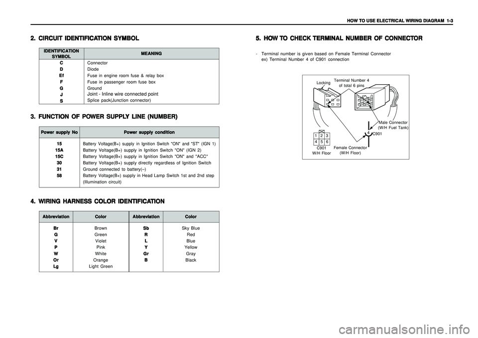
- Terminal number is given based on Female Terminal Connector
ex) Terminal Number 4 of C901 connection
LockingTerminal Number 4
of total 6 pins
Male Connector
(W/H Fuel Tank)
4
C901
Female Connector
(W/H Floor) C901
W/H Floor132
465
Page 1865 of 2053
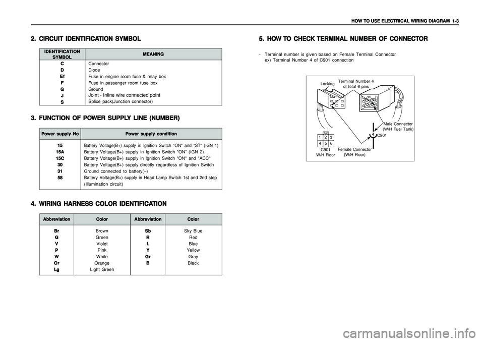
HOW TO USE ELECTRICAL WIRING DIAGRAM HOW TO USE ELECTRICAL WIRING DIAGRAM HOW TO USE ELECTRICAL WIRING DIAGRAM HOW TO USE ELECTRICAL WIRING DIAGRAM
HOW TO USE ELECTRICAL WIRING DIAGRAM
1-3 1-31-3 1-3
1-3
Connector
Diode
Fuse in engine room fuse & relay box
Fuse in passenger room fuse box
GroundJoint - Inline wire connected pointSplice pack(Junction connector) C CC C
C
D DD D
D
Ef EfEf Ef
Ef
F FF F
F
G GG G
G
J JJ J
J
S SS S
S
2. 2.2. 2.
2.
CIRCUIT IDENTIFICA CIRCUIT IDENTIFICACIRCUIT IDENTIFICA CIRCUIT IDENTIFICA
CIRCUIT IDENTIFICA
TION SYMBOL TION SYMBOLTION SYMBOL TION SYMBOL
TION SYMBOL
3. 3.3. 3.
3.
FUNCTION OF PO FUNCTION OF POFUNCTION OF PO FUNCTION OF PO
FUNCTION OF PO
WER SUPPL WER SUPPLWER SUPPL WER SUPPL
WER SUPPL
Y LINE (NUMBER) Y LINE (NUMBER)Y LINE (NUMBER) Y LINE (NUMBER)
Y LINE (NUMBER)
IDENTIFICATION IDENTIFICATIONIDENTIFICATION IDENTIFICATION
IDENTIFICATION
SYMBOL SYMBOLSYMBOL SYMBOL
SYMBOLMEANING MEANINGMEANING MEANING
MEANINGPower supply No Power supply NoPower supply No Power supply No
Power supply No
Power supply condition Power supply conditionPower supply condition Power supply condition
Power supply condition
Battery Voltage(B+) supply in Ignition Switch "ON" and "ST" (IGN 1)Battery Voltage(B+) supply in Ignition Switch "ON" (IGN 2)
Battery Voltage(B+) supply in Ignition Switch "ON" and "ACC"
Battery Voltage(B+) supply directly regardless of Ignition Switch
Ground connected to battery(–)Battery Voltage(B+) supply in Head Lamp Switch 1st and 2nd step(Illumination circuit) 15 1515 15
15
15A 15A15A 15A
15A
15C 15C15C 15C
15C
30 3030 30
30
31 3131 31
31
58 5858 58
58
Abbreviation AbbreviationAbbreviation Abbreviation
Abbreviation
Color ColorColor Color
Color
Brown
Green
Violet
Pink
White
Orange
Light Green Br BrBr Br
Br
G GG G
G
V VV V
V
P PP P
P
W WW W
W
Or OrOr Or
Or
Lg LgLg Lg
Lg
Abbreviation AbbreviationAbbreviation Abbreviation
Abbreviation
Color ColorColor Color
Color
Sky Blue
Red
Blue
Yellow
Gray
Black Sb SbSb Sb
Sb
R RR R
R
L LL L
L
Y YY Y
Y
Gr GrGr Gr
Gr
B BB B
B
4. 4.4. 4.
4.
WIRING HARNESS COLOR IDENTIFICA WIRING HARNESS COLOR IDENTIFICAWIRING HARNESS COLOR IDENTIFICA WIRING HARNESS COLOR IDENTIFICA
WIRING HARNESS COLOR IDENTIFICA
TION TIONTION TION
TION5. 5.5. 5.
5.
HO HOHO HO
HO
W W W W
W
T TT T
T
O CHECK O CHECK O CHECK O CHECK
O CHECK
TERMINAL NUMBER OF CONNECT TERMINAL NUMBER OF CONNECTTERMINAL NUMBER OF CONNECT TERMINAL NUMBER OF CONNECT
TERMINAL NUMBER OF CONNECT
OR OROR OR
OR
- Terminal number is given based on Female Terminal Connector
ex) Terminal Number 4 of C901 connection
LockingTerminal Number 4
of total 6 pins
Male Connector
(W/H Fuel Tank)
4
C901
Female Connector
(W/H Floor) C901
W/H Floor132
465
Page 1898 of 2053
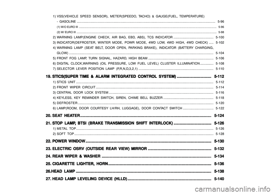
1) VSS(VEHICLE SPEED SENSOR), METER(SPEEDO, TACHO) & GAUGE(FUEL, TEMPERATURE)
- GASOLINE ........................................................................................................................................................... 5-96
(1) W/O EURO III .................................................................................................................................................................................... 5-96
(2) W/ EURO III ....................................................................................................................................................................................... 5-98
2) WARNING LAMP(ENGINE CHECK, AIR BAG, EBD, ABS), TCS INDICATOR............................................. 5-100
3) INDICATOR(DEFROSTER, WINTER MODE, POWR MODE, 4WD LOW, 4WD HIGH, 4WD CHECK)..... 5-102
4) WARNING LAMP (SEAT BELT, DOOR OPEN, PARKING BRAKE), INDICATOR (BATTERY CHARGING,
GLOW).................................................................................................................................................................. 5-104
5) FRONT FOG LAMP, TURN SIGNAL, HAZARD, HIGH BEAM ......................................................................... 5-106
6) DIGITAL CLOCK,WARNING (OIL PRESSURE, LOW FUEL LEVEL) CLUSTER ILLUMINATION............... 5-108
7) SELECTOR LEVER POSITION LAMP (P,R,N,D,3,2,1).................................................................................... 5-110
19. 19.19. 19.
19.
STICS(SUPER STICS(SUPER STICS(SUPER STICS(SUPER
STICS(SUPER
TIME & ALARM INTEGRA TIME & ALARM INTEGRATIME & ALARM INTEGRA TIME & ALARM INTEGRA
TIME & ALARM INTEGRA
TED CONTR TED CONTRTED CONTR TED CONTR
TED CONTR
OL SYSTEM) OL SYSTEM)OL SYSTEM) OL SYSTEM)
OL SYSTEM)
................................ ................................................................ ................................
................................
5-112 5-112 5-112 5-112
5-112
1) STICS UNIT .......................................................................................................................................................... 5-112
2) FRONT WIPER CIRCUIT.................................................................................................................................... 5-114
3) CENTRAL DOOR LOCK SYSTEM ..................................................................................................................... 5-116
4) KEYLESS, KEY REMINDER SWITCH, SIREN, CHIME BELL BUZZER ........................................................ 5-118
5) DEFROSTER........................................................................................................................................................ 5-120
6) LAMP(ROOM, DOOR COURTESY LH/RH, LUGGAGE), DOOR CONTACT SWITCH .................................. 5-122
20. 20.20. 20.
20.
SEA SEASEA SEA
SEA
T HEA T HEAT HEA T HEA
T HEA
TER TERTER TER
TER
.......................................................................................................................... .................................................................................................................................................................................................................................................... ..........................................................................................................................
..........................................................................................................................
5-124 5-124 5-124 5-124
5-124
21. 21.21. 21.
21.
ST STST ST
ST
OP LAMP OP LAMPOP LAMP OP LAMP
OP LAMP
, ,, ,
,
BTSI (BRAKE BTSI (BRAKE BTSI (BRAKE BTSI (BRAKE
BTSI (BRAKE
TRANSMISSION SHIFT INTERLOCK) TRANSMISSION SHIFT INTERLOCK)TRANSMISSION SHIFT INTERLOCK) TRANSMISSION SHIFT INTERLOCK)
TRANSMISSION SHIFT INTERLOCK)
................................... ...................................................................... ...................................
...................................
5-126 5-126 5-126 5-126
5-126
1) METAL TOP .......................................................................................................................................................... 5-126
2) SOFT TOP............................................................................................................................................................ 5-128
22. 22.22. 22.
22.
POWER WINDOW POWER WINDOWPOWER WINDOW POWER WINDOW
POWER WINDOW
..................................................................................................................... .......................................................................................................................................................................................................................................... .....................................................................................................................
.....................................................................................................................
5-130 5-130 5-130 5-130
5-130
23. 23.23. 23.
23.
ELECTRIC OSRV (OUTSIDE REAR VIEW) MIRROR ELECTRIC OSRV (OUTSIDE REAR VIEW) MIRRORELECTRIC OSRV (OUTSIDE REAR VIEW) MIRROR ELECTRIC OSRV (OUTSIDE REAR VIEW) MIRROR
ELECTRIC OSRV (OUTSIDE REAR VIEW) MIRROR
........................................................... ...................................................................................................................... ...........................................................
...........................................................
5-132 5-132 5-132 5-132
5-132
24. 24.24. 24.
24.
REAR REAR REAR REAR
REAR
WIPER & WIPER & WIPER & WIPER &
WIPER &
W WW W
W
ASHER ASHERASHER ASHER
ASHER
...................................................................................................... ............................................................................................................................................................................................................ ......................................................................................................
......................................................................................................
5-134 5-134 5-134 5-134
5-134
25. 25.25. 25.
25.
CIGARETTE LIGHTER, HORN CIGARETTE LIGHTER, HORNCIGARETTE LIGHTER, HORN CIGARETTE LIGHTER, HORN
CIGARETTE LIGHTER, HORN
................................................................................................ ................................................................................................................................................................................................ ................................................................................................
................................................................................................
5-136 5-136 5-136 5-136
5-136
26.HEAD LAMP 26.HEAD LAMP26.HEAD LAMP 26.HEAD LAMP
26.HEAD LAMP
.............................................................................................................................. ............................................................................................................................................................................................................................................................ ..............................................................................................................................
..............................................................................................................................
5-138 5-138 5-138 5-138
5-138
27. 27.27. 27.
27.
HEAD LAMP LEVELING DEVICE (HLLD) HEAD LAMP LEVELING DEVICE (HLLD)HEAD LAMP LEVELING DEVICE (HLLD) HEAD LAMP LEVELING DEVICE (HLLD)
HEAD LAMP LEVELING DEVICE (HLLD)
.............................................................................. ............................................................................................................................................................ ..............................................................................
..............................................................................
5-140 5-140 5-140 5-140
5-140
Page 1994 of 2053
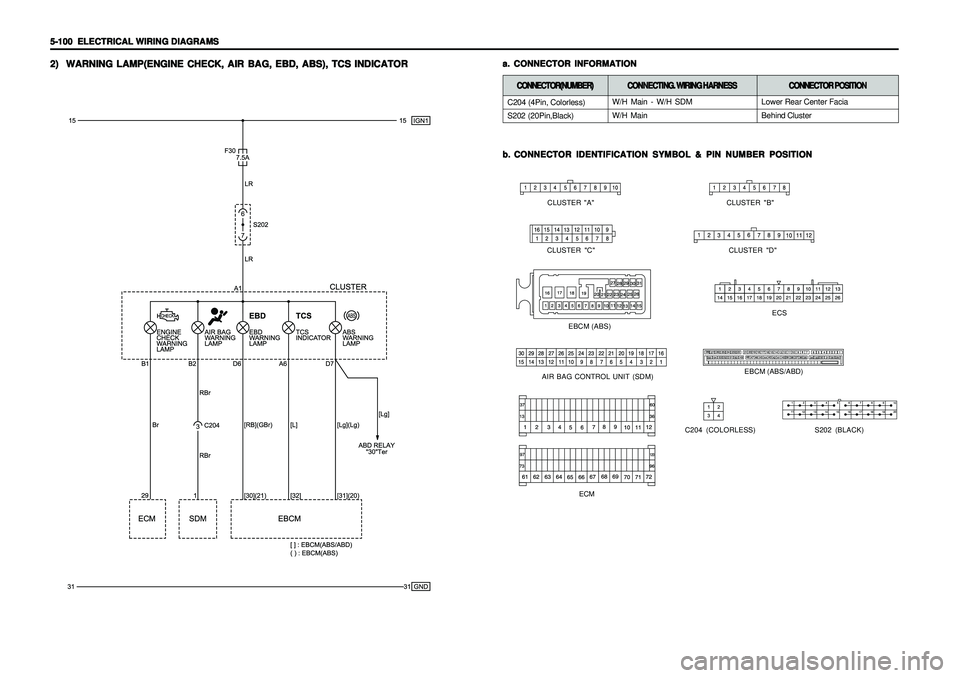
5-100 5-100 5-100 5-100
5-100
ELECTRICAL WIRING DIAGRAMS ELECTRICAL WIRING DIAGRAMSELECTRICAL WIRING DIAGRAMS ELECTRICAL WIRING DIAGRAMS
ELECTRICAL WIRING DIAGRAMS2) 2)2) 2)
2)
WARNING LAMP(ENGINE CHECK, AIR BAG, EBD, ABS), TCS INDICATOR WARNING LAMP(ENGINE CHECK, AIR BAG, EBD, ABS), TCS INDICATORWARNING LAMP(ENGINE CHECK, AIR BAG, EBD, ABS), TCS INDICATOR WARNING LAMP(ENGINE CHECK, AIR BAG, EBD, ABS), TCS INDICATOR
WARNING LAMP(ENGINE CHECK, AIR BAG, EBD, ABS), TCS INDICATOR
b. b.b. b.
b.
CONNECTOR IDENTIFICATION SYMBOL & PIN NUMBER POSITION CONNECTOR IDENTIFICATION SYMBOL & PIN NUMBER POSITIONCONNECTOR IDENTIFICATION SYMBOL & PIN NUMBER POSITION CONNECTOR IDENTIFICATION SYMBOL & PIN NUMBER POSITION
CONNECTOR IDENTIFICATION SYMBOL & PIN NUMBER POSITION
C204 (COLORLESS)
a. a.a. a.
a.
CONNECTOR INFORMATION CONNECTOR INFORMATIONCONNECTOR INFORMATION CONNECTOR INFORMATION
CONNECTOR INFORMATION
S202 (BLACK)
AIR BAG CONTROL UNIT (SDM)
ECS
EBCM (ABS/ABD)
CLUSTER "B"
CLUSTER "A"
CLUSTER "C" CLUSTER "D"
EBCM (ABS)
C204 (4Pin, Colorless)
S202 (20Pin,Black)CONNECTOR(NUMBER) CONNECTOR(NUMBER)CONNECTOR(NUMBER) CONNECTOR(NUMBER)
CONNECTOR(NUMBER)
CONNECTING. WIRING HARNESS CONNECTING. WIRING HARNESSCONNECTING. WIRING HARNESS CONNECTING. WIRING HARNESS
CONNECTING. WIRING HARNESS
CONNECTOR POSITION CONNECTOR POSITIONCONNECTOR POSITION CONNECTOR POSITION
CONNECTOR POSITION
W/H Main - W/H SDM
W/H MainLower Rear Center Facia
Behind Cluster
ECM