1997 SSANGYONG KORANDO ECO mode
[x] Cancel search: ECO modePage 1161 of 2053
5A-66 AUTOMATIC TRANSMISSION
SSANGYONG MY2002
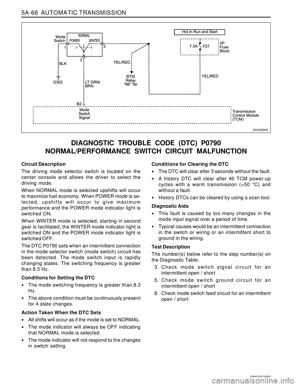
Circuit Description
The driving mode selector switch is located on the
center console and allows the driver to select the
driving mode.
When NORMAL mode is selected upshifts will occur
to maximize fuel economy. When POWER mode is se-
lected, upshifts will occur to give maximum
performance and the POWER mode indicator light is
switched ON.
When WINTER mode is selected, starting in second
gear is facilitated, the WINTER mode indicator light is
switched ON and the POWER mode indicator light is
switched OFF.
The DTC P0790 sets when an intermittent connection
in the mode selector switch (mode switch) circuit has
been detected. The mode switch input is rapidly
changing states. The switching frequency is greater
than 8.3 Hz.
Conditions for Setting the DTC
The mode switching frequency is greater than 8.3
Hz.
The above condition must be continuously present
for 4 state changes.
Action Taken When the DTC Sets
All shifts will occur as if the mode is set to NORMAL.
The mode indicator will always be OFF indicating
that NORMAL mode is selected.
The mode indicator will not respond to the changes
in switch setting.
DIAGNOSTIC TROUBLE CODE (DTC) P0790
NORMAL/PERFORMANCE SWITCH CIRCUIT MALFUNCTION
Conditions for Clearing the DTC
The DTC will clear after 3 seconds without the fault.
A history DTC will clear after 40 TCM power-up
cycles with a warm transmission (>50 °C) and
without a fault.
History DTCs can be cleared by using a scan tool.
Diagnostic Aids
This fault is caused by too many changes in the
mode input signal over a period of time.
Typical causes would be an intermittent connection
in the switch or wiring or an intermittent short to
ground in the wiring.
Test Description
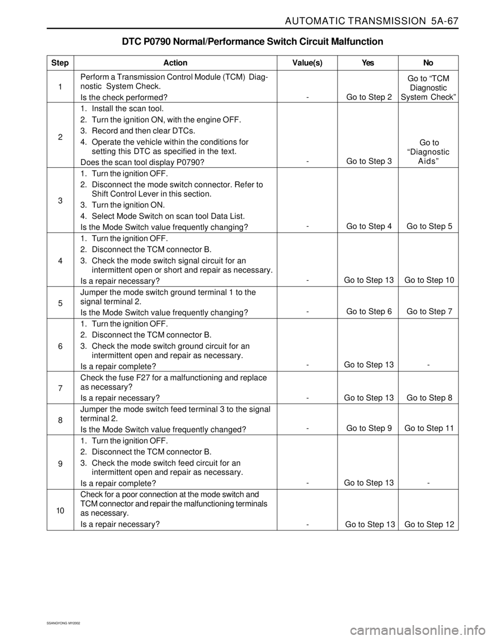
The number(s) below refer to the step number(s) on
the Diagnostic Table.
3. Check mode switch signal circuit for an
intermittent open / short
5. Check mode switch ground circuit for an
intermittent open / short
8. Check mode switch feed circuit for an intermittent
open / short
KAA5A5NA
Page 1162 of 2053
AUTOMATIC TRANSMISSION 5A-67
SSANGYONG MY2002
DTC P0790 Normal/Performance Switch Circuit Malfunction
1Perform a Transmission Control Module (TCM) Diag-
nostic System Check.
Is the check performed?
1. Install the scan tool.
2. Turn the ignition ON, with the engine OFF.
3. Record and then clear DTCs.
4. Operate the vehicle within the conditions for
setting this DTC as specified in the text.
Does the scan tool display P0790?
1. Turn the ignition OFF.
2. Disconnect the mode switch connector. Refer to
Shift Control Lever in this section.
3. Turn the ignition ON.
4. Select Mode Switch on scan tool Data List.
Is the Mode Switch value frequently changing?
1. Turn the ignition OFF.
2. Disconnect the TCM connector B.
3. Check the mode switch signal circuit for an
intermittent open or short and repair as necessary.
Is a repair necessary?
Jumper the mode switch ground terminal 1 to the
signal terminal 2.
Is the Mode Switch value frequently changing?
1. Turn the ignition OFF.
2. Disconnect the TCM connector B.
3. Check the mode switch ground circuit for an
intermittent open and repair as necessary.
Is a repair complete?
Check the fuse F27 for a malfunctioning and replace
as necessary?
Is a repair necessary?
Jumper the mode switch feed terminal 3 to the signal
terminal 2.
Is the Mode Switch value frequently changed?
1. Turn the ignition OFF.
2. Disconnect the TCM connector B.
3. Check the mode switch feed circuit for an
intermittent open and repair as necessary.
Is a repair complete?
Check for a poor connection at the mode switch and
TCM connector and repair the malfunctioning terminals
as necessary.
Is a repair necessary?
StepAction Value(s) Yes No
2
3
- Go to Step 6 Go to Step 7 5
- Go to Step 13 - 6
- Go to Step 13 Go to Step 10 4
- Go to Step 13 Go to Step 8 7
- Go to Step 9 Go to Step 11 8
- Go to Step 13 - 9
10
- Go to Step 2Go to “TCM
Diagnostic
System Check”
-
Go to Step 4 Go to Step 5
- Go to Step 3 Go to
“Diagnostic
Aids”
- Go to Step 13 Go to Step 12
Page 1163 of 2053
5A-68 AUTOMATIC TRANSMISSION
SSANGYONG MY2002
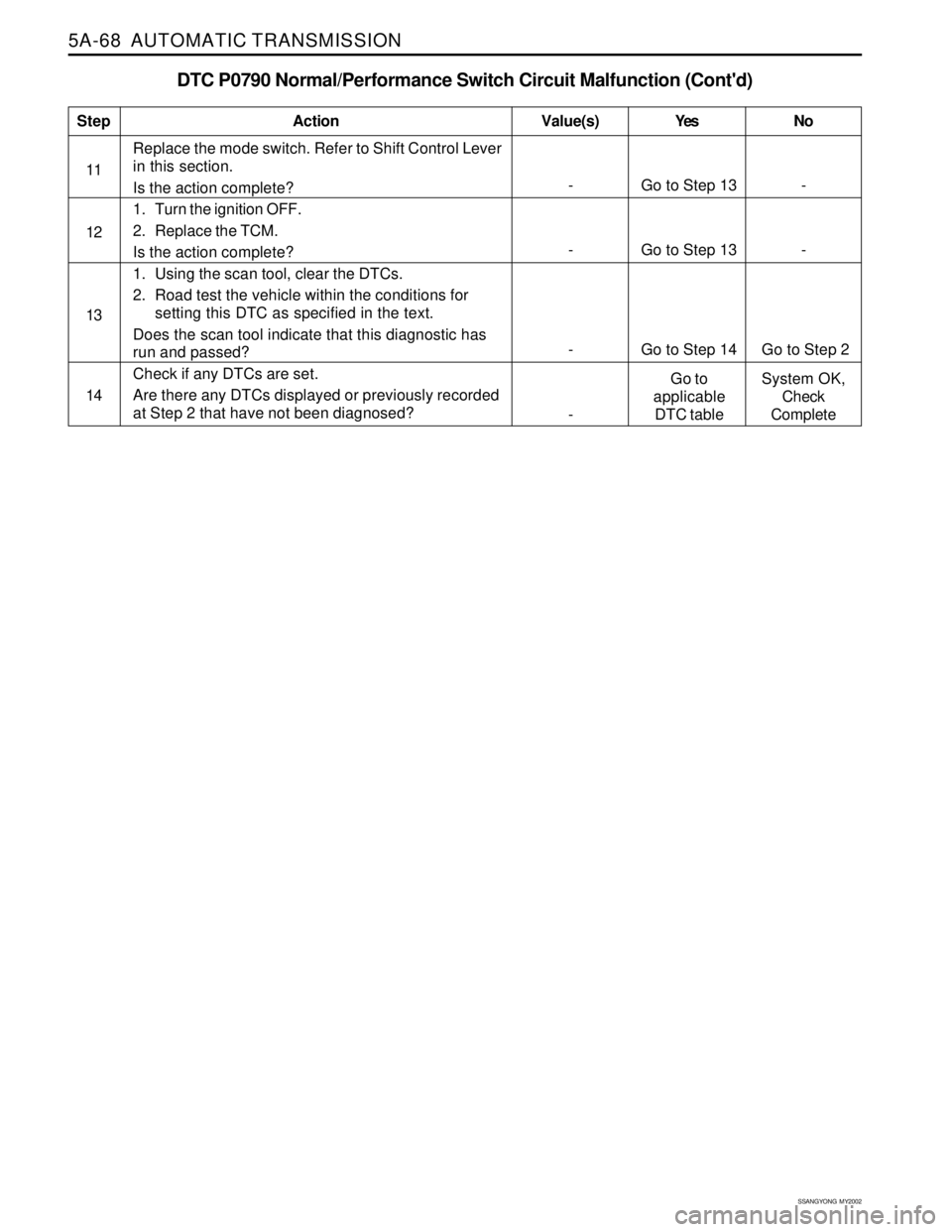
DTC P0790 Normal/Performance Switch Circuit Malfunction (Cont'd)
Replace the mode switch. Refer to Shift Control Lever
in this section.
Is the action complete?
1. Turn the ignition OFF.
2. Replace the TCM.
Is the action complete?
1. Using the scan tool, clear the DTCs.
2. Road test the vehicle within the conditions for
setting this DTC as specified in the text.
Does the scan tool indicate that this diagnostic has
run and passed?
Check if any DTCs are set.
Are there any DTCs displayed or previously recorded
at Step 2 that have not been diagnosed?
StepAction Value(s) Yes No
11
12
- Go to Step 14 Go to Step 2
14
- Go to Step 13 -
13
- Go to Step 13 -
-Go to
applicable
DTC tableSystem OK,
Check
Complete
Page 1165 of 2053
5A-70 AUTOMATIC TRANSMISSION
SSANGYONG MY2002
Circuit Description
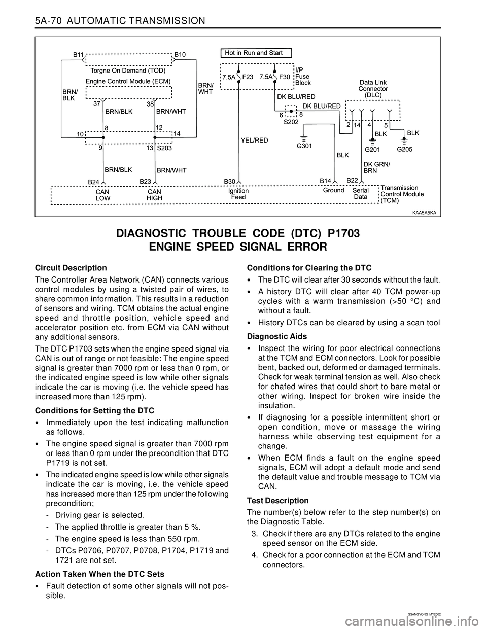
The Controller Area Network (CAN) connects various
control modules by using a twisted pair of wires, to
share common information. This results in a reduction
of sensors and wiring. TCM obtains the actual engine
speed and throttle position, vehicle speed and
accelerator position etc. from ECM via CAN without
any additional sensors.
The DTC P1703 sets when the engine speed signal via
CAN is out of range or not feasible: The engine speed
signal is greater than 7000 rpm or less than 0 rpm, or
the indicated engine speed is low while other signals
indicate the car is moving (i.e. the vehicle speed has
increased more than 125 rpm).
Conditions for Setting the DTC
Immediately upon the test indicating malfunction
as follows.
The engine speed signal is greater than 7000 rpm
or less than 0 rpm under the precondition that DTC
P1719 is not set.
The indicated engine speed is low while other signals
indicate the car is moving, i.e. the vehicle speed
has increased more than 125 rpm under the following
precondition;
- Driving gear is selected.
- The applied throttle is greater than 5 %.
- The engine speed is less than 550 rpm.
- DTCs P0706, P0707, P0708, P1704, P1719 and
1721 are not set.
Action Taken When the DTC Sets
Fault detection of some other signals will not pos-
sible.
DIAGNOSTIC TROUBLE CODE (DTC) P1703
ENGINE SPEED SIGNAL ERROR
Conditions for Clearing the DTC
The DTC will clear after 30 seconds without the fault.
A history DTC will clear after 40 TCM power-up
cycles with a warm transmission (>50 °C) and
without a fault.
History DTCs can be cleared by using a scan tool
Diagnostic Aids
Inspect the wiring for poor electrical connections
at the TCM and ECM connectors. Look for possible
bent, backed out, deformed or damaged terminals.
Check for weak terminal tension as well. Also check
for chafed wires that could short to bare metal or
other wiring. Inspect for broken wire inside the
insulation.
If diagnosing for a possible intermittent short or
open condition, move or massage the wiring
harness while observing test equipment for a
change.
When ECM finds a fault on the engine speed
signals, ECM will adopt a default mode and send
the default value and trouble message to TCM via
CAN.
Test Description
The number(s) below refer to the step number(s) on
the Diagnostic Table.
3. Check if there are any DTCs related to the engine
speed sensor on the ECM side.
4. Check for a poor connection at the ECM and TCM
connectors.
KAA5A5KA
Page 1168 of 2053
AUTOMATIC TRANSMISSION 5A-73
SSANGYONG MY2002
If diagnosing for a possible intermittent short or
open condition, move or massage the wiring harness
while observing test equipment for a change.
When ECM finds a fault on the vehicle speed
signals, ECM will adopt a default mode and send
the default value and trouble message to TCM via
CAN.Test Description
The number(s) below refer to the step number(s) on
the Diagnostic Table.
3. Check if there are any DTCs related to the vehicle
speed sensor on the ECM side.
4. Check a poor connection at the ECM and TCM
connectors.
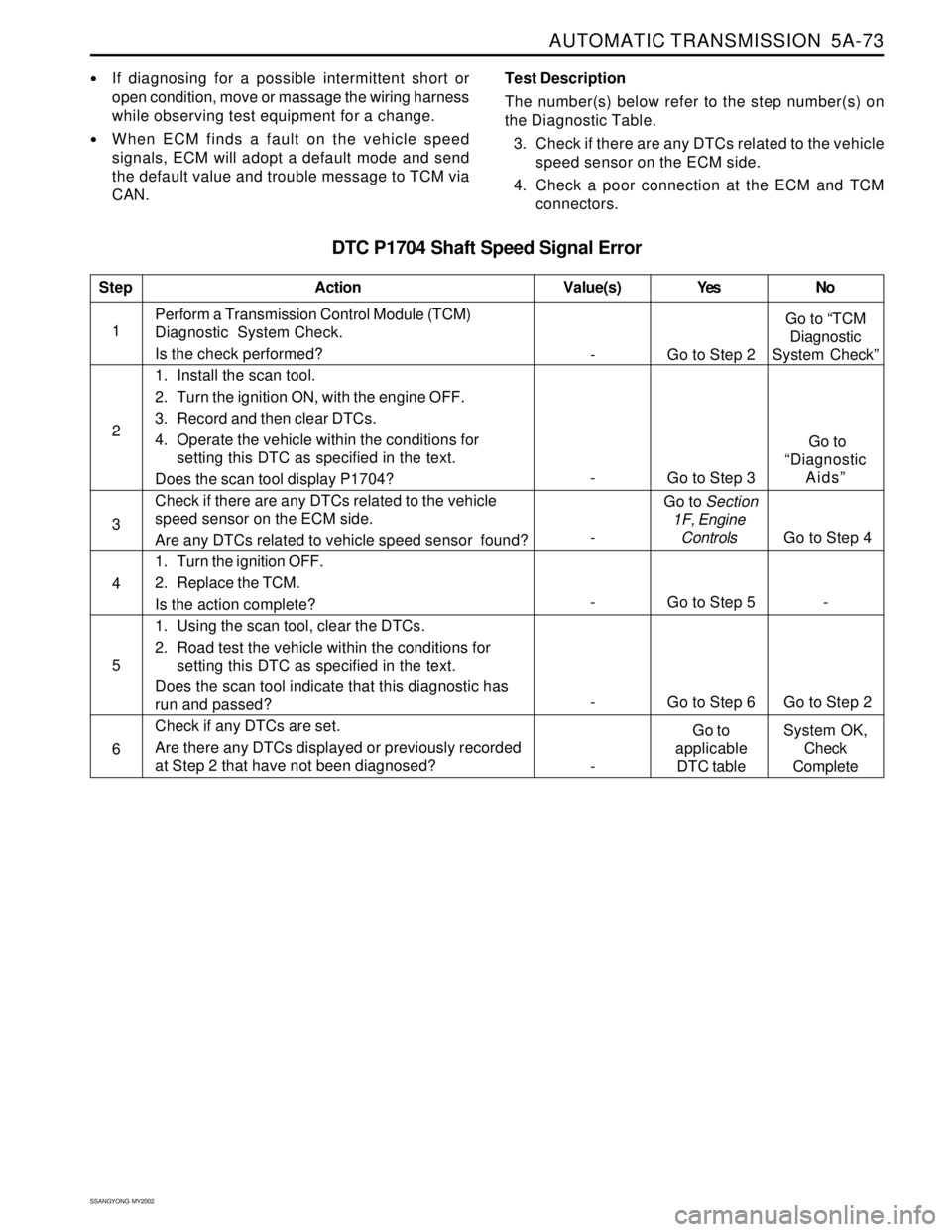
DTC P1704 Shaft Speed Signal Error
1Perform a Transmission Control Module (TCM)
Diagnostic System Check.
Is the check performed?
1. Install the scan tool.
2. Turn the ignition ON, with the engine OFF.
3. Record and then clear DTCs.
4. Operate the vehicle within the conditions for
setting this DTC as specified in the text.
Does the scan tool display P1704?
Check if there are any DTCs related to the vehicle
speed sensor on the ECM side.
Are any DTCs related to vehicle speed sensor found?
1. Turn the ignition OFF.
2. Replace the TCM.
Is the action complete?
1. Using the scan tool, clear the DTCs.
2. Road test the vehicle within the conditions for
setting this DTC as specified in the text.
Does the scan tool indicate that this diagnostic has
run and passed?
Check if any DTCs are set.
Are there any DTCs displayed or previously recorded
at Step 2 that have not been diagnosed?
StepAction Value(s) Yes No
2
3
- Go to Step 5 - 4
- Go to Step 6 Go to Step 2 5
6
- Go to Step 2Go to “TCM
Diagnostic
System Check”
- Go to Step 3 Go to
“Diagnostic
Aids”
- Go to Section
1F, Engine
Controls
Go to Step 4
-Go to
applicable
DTC tableSystem OK,
Check
Complete
Page 1169 of 2053
5A-74 AUTOMATIC TRANSMISSION
SSANGYONG MY2002
Circuit Description
The battery voltage monitoring input is connected to
the positive side of the battery. This signal is taken
from the main supply to the TCM.
If the battery voltage at the TCM falls below the thresh-
old value, DTC P1708 will be set and the transmission
will adopt a low voltage mode of operating in which
shifts into first gear are inhibited. All other shifts are
attempted but may not occur because of the reduced
voltage. This condition normally occurs only when the
battery is in poor condition.
When system voltage recovers, the TCM will resume
normal operation after a 30 seconds delay period.
Conditions for Setting the DTC
The engine speed is greater than 550 RPM.
A driving gear is selected or one of DTCs P0706,
P0707 and P0708 is set.
The indicated supply voltage falls below a linear
temperature characteristic threshold or below that
required to operate the CPU. If the TCM measures
the supply voltage at less than that required for it
to be operating, the DTC sets immediately.
Action Taken When the DTC Sets
1st gear is inhibited.
S6 is inhibited.
S5 standby current is zero.
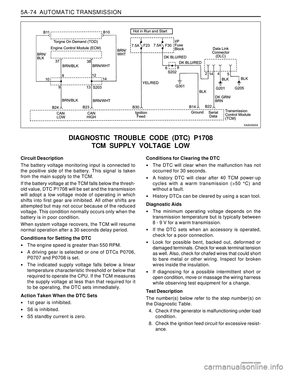
DIAGNOSTIC TROUBLE CODE (DTC) P1708
TCM SUPPLY VOLTAGE LOW
Conditions for Clearing the DTC
The DTC will clear when the malfunction has not
occurred for 30 seconds.
A history DTC will clear after 40 TCM power-up
cycles with a warm transmission (>50 °C) and
without a fault.
History DTCs can be cleared by using a scan tool.
Diagnostic Aids
The minimum operating voltage depends on the
transmission temperature but is typically between
8 - 9 V for a warm transmission.
If the DTC sets when an accessory is operated,
check for a poor connection.
Look for possible bent, backed out, deformed or
damaged terminals. Check for weak terminal tension
as well. Also, check for chafed wires that could short
to bare metal or other wiring. Inspect for broken
wires inside the insulation.
If diagnosing for a possible intermittent short or
open condition, move or massage the wiring harness
while observing test equipment for a change.
Test Description
The number(s) below refer to the step number(s) on
the Diagnostic Table.
4. Check if the generator is malfunctioning under load
condition.
8. Check the ignition feed circuit for excessive resist-
ance.
KAA5A5KA
Page 1171 of 2053
5A-76 AUTOMATIC TRANSMISSION
SSANGYONG MY2002
Circuit Description
The battery voltage monitoring input is connected to
the positive side of the battery. This signal is taken
from the main supply to the TCM.
If the battery voltage is greater than 16.5 V, DTC P1709
will be set and the transmission will adopt limp home
mode and all solenoids are turned OFF.
Conditions for Setting the DTC
The indicated supply voltage is greater than 16.5 V.
The malfunction triggers immediately after this
condition exists.
Action Taken When the DTC Sets
All solenoids are turned OFF while the high battery
voltage condition is detected.
The transmission goes into Limp Home Mode (LHM).
Conditions for Clearing the DTC
The DTC will clear when the malfunction has not
occurred for 30 seconds.
A history DTC will clear after 40 TCM power-up
cycles with a warm transmission (>50 °C) and
without a fault.
History DTCs can be cleared by using a scan tool.
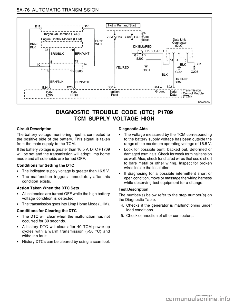
DIAGNOSTIC TROUBLE CODE (DTC) P1709
TCM SUPPLY VOLTAGE HIGH
Diagnostic Aids
The voltage measured by the TCM corresponding
to the battery supply voltage has been outside the
range of the maximum operating voltage of 16.5 V.
Look for possible bent, backed out, deformed or
damaged terminals. Check for weak terminal tension
as well. Also, check for chafed wires that could short
to bare metal or other wiring. Inspect for broken
wires inside the insulation.
If diagnosing for a possible intermittent short or
open condition, move or massage the wiring harness
while observing test equipment for a change.
Test Description
The number(s) below refer to the step number(s) on
the Diagnostic Table.
4. Checks if the generator is malfunctioning under
load conditions.
5. Check connection of other connectors.
KAA5A5KA
Page 1173 of 2053
5A-78 AUTOMATIC TRANSMISSION
SSANGYONG MY2002
Circuit Description
The Air Conditioning Switch circuit indicates the state
of the air conditioning compressor clutch (on or off).
This signal is available to the TCM only on vehicles
fitted with air conditioning.
The DTC 1710 sets when an intermittent connection in
the air conditioning switch circuit has been detected.
The switch input is rapidly changing states and the
switching frequency is greater than 8.3 Hz.
Conditions for Setting the DTC
The mode switching frequency is greater than 8.3
Hz.
The above condition must be continuously present
for 4 state changes.
Action Taken When the DTC Sets
The TCM does not compensate for torque variation
due to air conditioning compressor clutch activation.
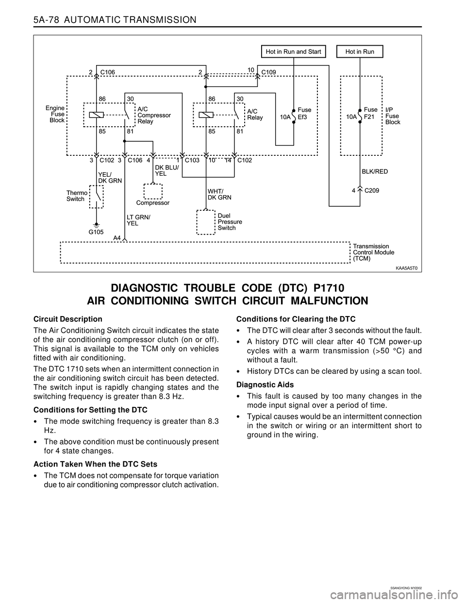
DIAGNOSTIC TROUBLE CODE (DTC) P1710
AIR CONDITIONING SWITCH CIRCUIT MALFUNCTION
Conditions for Clearing the DTC
The DTC will clear after 3 seconds without the fault.
A history DTC will clear after 40 TCM power-up
cycles with a warm transmission (>50 °C) and
without a fault.
History DTCs can be cleared by using a scan tool.
Diagnostic Aids
This fault is caused by too many changes in the
mode input signal over a period of time.
Typical causes would be an intermittent connection
in the switch or wiring or an intermittent short to
ground in the wiring.
KAA5A5T0