Page 175 of 2053
1F1 -- 12 M162 ENGINE CONTROLS
D AEW OO M Y_2000
KAB1F060
ECM WIRING DIAGRAM (3.2L DOHC -- 6 OF 7) (MSE 3.62S)
Page 176 of 2053
M162 ENGINE CONTROLS 1F1 -- 13
D AEW OO M Y_2000
KAB1F070
ECM WIRING DIAGRAM (3.2L DOHC -- 7 OF 7) (MSE 3.62S)
Page 177 of 2053

1F1 -- 14 M162 ENGINE CONTROLS
D AEW OO M Y_2000
DIAGNOSIS
FAILURE CODE DIAGNOSIS
CLEARING FAILURE CODES
Notice:To prevent Engine Control Module (ECM) damage, the key must be OFF when disconnecting or reconnecting
the power to the ECM (for example battery cable, ECM pigtail connector, ECM fuse, jumper cables, etc.)
Parameters listed in the table may not be exactly the same as your reading due to the type of instrument or other
factors. If a failure code is displayed during the “TROUBLE CODE” in scan tool check mode, check the circuit for the
code listed in the table below. For details of each code, turn to the page referred to under the “See Page” for the re-
spective “Failure Code” in the below table.
Failure codes should be cleared after repairs have been completed.
FAILURE CODES TABLE
Failure
codeSee
PageDescription
001F1 -- 66Engine coolant temperature sensor low voltage
011F1 -- 66Engine coolant temperature sensor high voltage
021F1 -- 66Engine coolant temperature sensor plausibility
031F1 -- 62Intake air temperature sensor low voltage
041F1 -- 62Intake air temperature sensor high voltage
051F1 -- 62Intake air temperature sensor plausibility
061F1 -- 66Engine coolant temperature insufficient for closed loop fuel control
081F1 -- 38System voltage too low
091F1 -- 62Mass air flow sensor plausibility
101F1 -- 62Mass air flow sensor low voltage
111F1 -- 62Mass air flow sensor high voltage
171F1 -- 23Crankshaft position sensor signal failure (no engine revolution signal)
181F1 -- 23Crankshaft position sensor signal failure (rpm > max. value)
191F1 -- 27Camshaft position senosr signal : No.1 cylinder recognition failure
201F1 -- 23Crankshaft position sensor signal failure (gap recognition failure)
211F1 -- 90Transmission coding failure
231F1 -- 88CAN communication failure : ASR/MSR
241F1 -- 88CAN communication failure : ABS
251F1 -- 94Communication with transponder missing
261F1 -- 88CAN communication failure : TCU (A/T only)
271F1 -- 88CAN communication failure : TOD (E32 only)
291F1 -- 89CAN communication failure : ID 200h not plausible
301F1 -- 89CAN communication failure : ID 208h not plausible
311F1 -- 89CAN communication failure : communication initialization failure
321F1 -- 78Engine rpm output circuit short circuit to battery
331F1 -- 78Engine rpm output circuit short circuit to ground or open
341F1 -- 43Fuel pump relay short circuit to battery
351F1 -- 43Fuel pump relay short circuit to ground or open
Page 181 of 2053

1F1 -- 18 M162 ENGINE CONTROLS
D AEW OO M Y_2000
IGNITION SYSTEM
This ignition system does not use a conventional distributor andcoil. It uses a crankshaft position sensor input to the
Engine Control Module (ECM). The ECM then determines Electronic Spark Timing (EST) and triggers the electronic
ignition system ignition coil.
This type of distributorless ignition system uses a‘‘waste spark” method of spark distribution. Each cylinder is paired
with the cylinder that is opposite it (1 -- 6 or 2 -- 5 or 3 -- 4). The spark occurs simultaneously in the cylinder coming up on
the compression stroke and in the cylinder coming up on the exhaust stroke. The cylinder on the exhaust stroke re-
quires very little of the available energy to fire the spark plug. The remaining energy is available to the spark plug in the
cylinder on the compression stroke.
These systems use the EST signal from the ECM to control the EST. The ECM uses the following information:
DEngine load (mass air flow sensor).
DEngine temperature.
DIntake air temperature.
DCrankshaft position.
DEngine speed (rpm).
YAA1F310
Page 183 of 2053
1F1 -- 20 M162 ENGINE CONTROLS
D AEW OO M Y_2000
IGNITION COIL
YAA1F240
The Electronic Ignition (EI) system ignition coil is located on the cylinder head cover. The double ended coils receive
the signal for the Engine Control Module (ECM) which controls the spark advance.
Each EI system ignition coil provides the high voltage to two spark plugs simultaneously;
T1/1: cylinder 2 and 5
T1/2: cylinder 3 and 4
T1/3: cylinder 1 and 6
The EI system ignition coil is not serviceable and must be replaced as an assembly.
Page 184 of 2053

M162 ENGINE CONTROLS 1F1 -- 21
D AEW OO M Y_2000
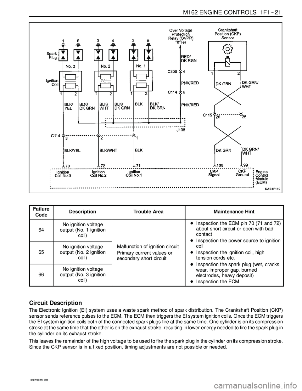
KAB1F140
Failure
CodeDescriptionTrouble AreaMaintenance Hint
64
No ignition voltage
output (No. 1 ignition
coil)DInspectiontheECMpin70(71and72)
about short circuit or open with bad
contact
DInspectionthepowersourcetoignition
65
No ignition voltage
output (No. 2 ignition
coil)Malfunction of ignition circuit
Primary current values or
secondary short circuit
DInspectionthepowersourcetoignition
coil
DInspection the ignition coil, high
tension cords etc.
DInspectionthesparkplug(wetcracks
66
No ignition voltage
output (No. 3 ignition
coil)DInspection the spark plug (wet, cracks,
wear, improper gap, burned
electrodes, heavy deposit)
DInspection the ECM
Circuit Description
The Electronic Ignition (EI) system uses a waste spark method of spark distribution. The Crankshaft Position (CKP)
sensor sends reference pulses to the ECM. The ECM then triggers the EI system ignition coils. Once the ECM triggers
the EI system ignition coils both of the connected spark plugs fire at the same time. One cylinder is on its compression
stroke at the same time that the other is on the exhaust stroke, resulting in lower energy needed to fire the spark plug in
the cylinder on its exhaust stroke.
This leaves the remainder of the high voltage to be used to fire the spark plug in the cylinder on its compression stroke.
Since the CKP sensor is in a fixed position, timing adjustments are not possible or needed.
Page 185 of 2053
1F1 -- 22 M162 ENGINE CONTROLS
D AEW OO M Y_2000
CRANKSHAFT POSITION (CKP) SENSOR
YAA1F250
This Electronic Ignition (EI) system uses inductive or pickup type magnetic Crankshaft Position (CKP) sensor. The
CKP sensor is located in the opposite side of the crankshaft pulley and triggers the pick-up wheel teeth which is
equipped 60 -- 2 teeth with a gap of 2 teeth at 360 degree spacing. This sensor protrudes through its mount to within 1.1
±0.14 mm.
The output of the sensor is a sinusoidal signal. Each tooth of the pick-up 60 -- 2 wheel generates a positive half wave.
The Engine Control Module (ECM) uses this sensor signal to generate timed ignition and injection pulses that it sends
to the ignition coils and to the fuel injectors.
Page 186 of 2053

M162 ENGINE CONTROLS 1F1 -- 23
D AEW OO M Y_2000
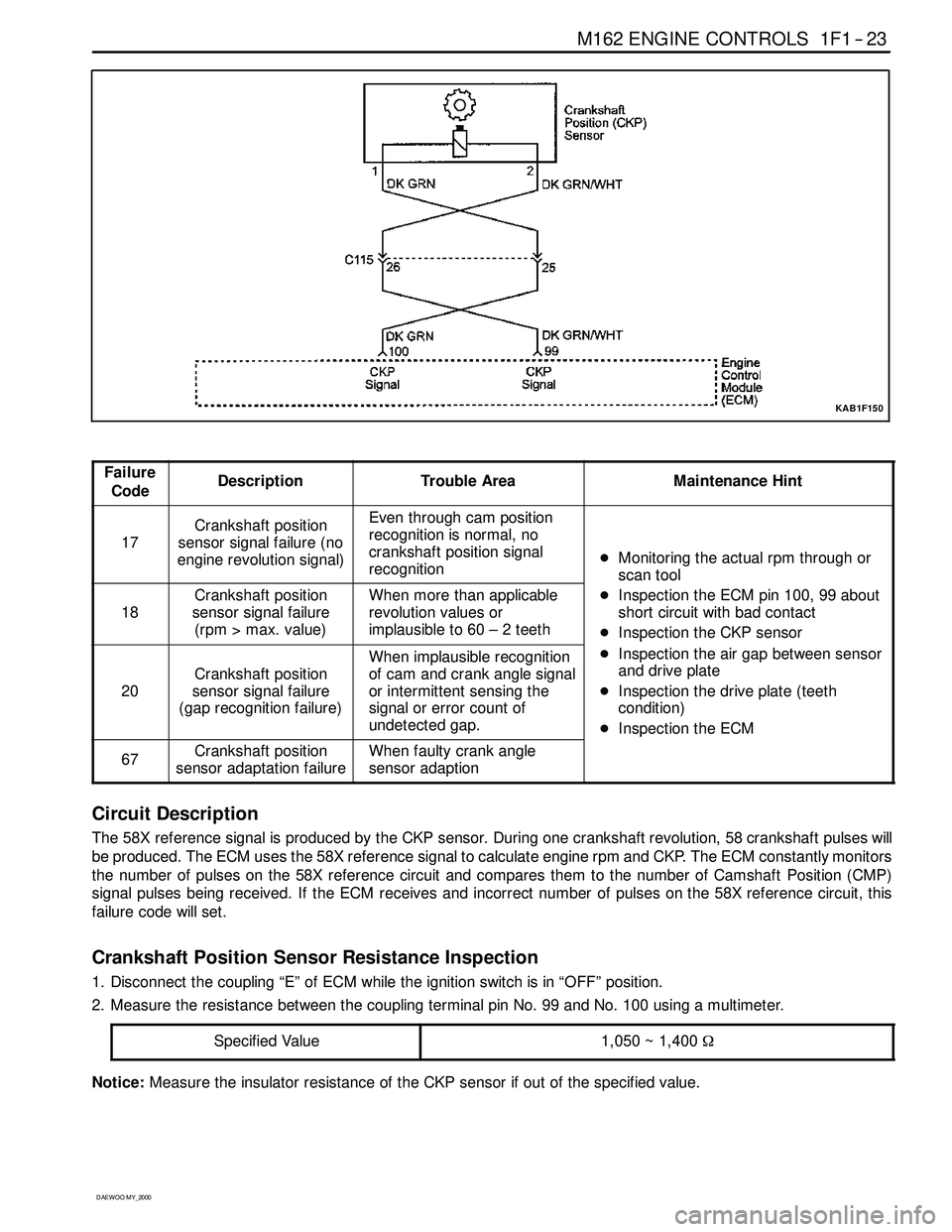
KAB1F150
Failure
CodeDescriptionTrouble AreaMaintenance Hint
17
Crankshaft position
sensor signal failure (no
engine revolution signal)Even through cam position
recognition is normal, no
crankshaft position signal
recognition
DMonitoring the actual rpm through or
scan tool
18
Crankshaft position
sensor signal failure
(rpm > max. value)When more than applicable
revolution values or
implausibleto60–2teeth
scantool
DInspection the ECM pin 100, 99 about
short circuit with bad contact
DInspection the CKP sensor
20
Crankshaft position
sensor signal failure
(gap recognition failure)
When implausible recognition
of cam and crank angle signal
or intermittent sensing the
signal or error count of
undetected gap.
p
DInspection the air gap between sensor
and drive plate
DInspection the drive plate (teeth
condition)
DInspection the ECM
67Crankshaft position
sensor adaptation failureWhen faulty crank angle
sensor adaption
p
Circuit Description
The 58X reference signal is produced by the CKP sensor. During one crankshaft revolution, 58 crankshaft pulseswill
be produced. The ECM uses the 58X reference signal to calculate engine rpm and CKP. The ECM constantly monitors
the number of pulses on the 58X reference circuit and compares them to the number of Camshaft Position (CMP)
signal pulses being received. If the ECM receives and incorrect number of pulses on the 58X reference circuit, this
failure code will set.
Crankshaft Position Sensor Resistance Inspection
1. Disconnect the coupling “E” of ECM while the ignition switch is in “OFF” position.
2. Measure the resistance between the coupling terminal pin No. 99 and No. 100 using a multimeter.
Specified Value
1,050 ~ 1,400Ω
Notice:Measure the insulator resistance of the CKP sensor if out of the specified value.