Page 1400 of 2053
SSANGYONG MY2002
5D1-78 TRANSFER CASE
31. Install the rear output shaft flange on rear output
shaft. Install the rubber seal, output shaft yoke
washer and nut. Tighten the nut and calk the nut
on the flat area.
Installation Notice
32. Install the shift motor. Refer to the “Shift Motor”
in this section.
33. Insert the brown wire and pin to speed sensor con-
nect and assemble the connector. Refer to “Front
and Rear Propeller Shaft Speed Sensors” in this
section.
34. Install the drain plug and tighten the drain plug.
Installation Notice
35. Fill the transfer case with 1.4 liters of ATF or equiva
lent.
Notice: Fluid level should be just below the filler
plug-hole.
36. Install the filler plug and tighten.
Installation Notice
37. Install the transfer case to the vehicle. Refer to
“Transfer Case” in the section.
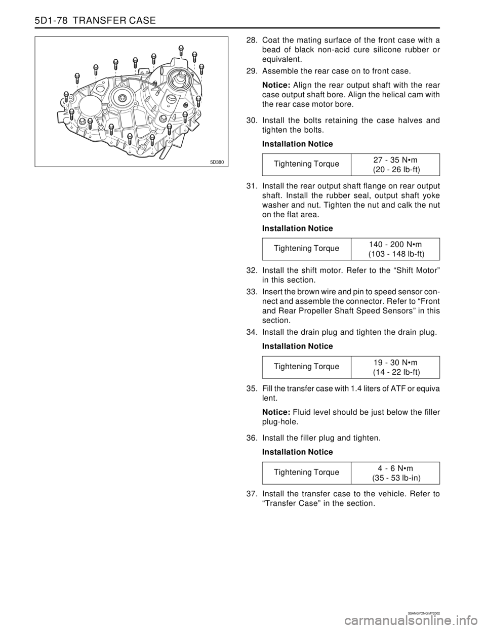
5D380
28. Coat the mating surface of the front case with a
bead of black non-acid cure silicone rubber or
equivalent.
29. Assemble the rear case on to front case.
Notice: Align the rear output shaft with the rear
case output shaft bore. Align the helical cam with
the rear case motor bore.
30. Install the bolts retaining the case halves and
tighten the bolts.
Installation Notice
Tightening Torque27 - 35 Nm
(20 - 26 lb-ft)
Tightening Torque140 - 200 Nm
(103 - 148 lb-ft)
Tightening Torque19 - 30 Nm
(14 - 22 lb-ft)
Tightening Torque4 - 6 Nm
(35 - 53 lb-in)
Page 1401 of 2053
SECTION 5D2
TRANSFER CASE (PART TIME - 4408)
TABLE OF CONTENTS
General Infromation and Operation..................5D2-2
4WD Operation Overview...................................5D2-2
System Structure...............................................5D2-3
2H Mode (Rear Wheel Drive)..............................5D2-5
4H Mode (4WD Drive - High Speed)...................5D2-6
4H Mode (4WD Drive - Low Speed)....................5D2-7
System Description...........................................5D2-8
Specifications....................................................5D2-9
Diagnostic Infromation and Procedures..........5D2-10
General Diagnosis...........................................5D2-10
Self-Diagnosis Test..........................................5D2-11
Diagnostic Diagram .........................................5D2-15
Component Locator .........................................5D2-16
Cross Sectional View.......................................5D2-16Transfer Case Assembly..................................5D2-17
Disassembly and Assembly............................5D2-18
Maintenance and Repair.................................5D2-20
On-Vehicle Service.............................................5D2-20
Maintenance of Transfer Case Lubricant...........5D2-20
4H and 4L Indicator .........................................5D2-21
TCCU Inspection.............................................5D2-21
Transfer Case Assembly..................................5D2-22
TCCU..............................................................5D2-24
Unit Repair........................................................5D2-25
Disassembly Procedure...................................5D2-25
Assembly Procedure.......................................5D2-35
Page 1415 of 2053
SSANGYONG MY2002
5D2-16 TRANSFER CASE (PART TIME - 4408)
� �
y y
����� �����
yyyyy yyyyy
�� ��
yy yy�� ��
yy yy
������ ������
������
������
yyyyyy yyyyyy
yyyyyy
yyyyyy
���� ����
����
yyyy yyyy
yyyy
��� ���
���
���
���
yyy yyy
yyy
yyy
yyy
������ ������ ������
yyyyyy yyyyyy yyyyyy
� �
y y
����� ����� �����
yyyyy yyyyy yyyyy
�� yy
���� yyyy
�� yy�� yy
� y��� �
y y
�� yy
�� yy
�� ��
��
yy yy
yy
�� yy�� yy
��� yyy
� y� �
y y
� �
y y�� yy
�� yy
�� yy
��� ���
yyy yyy� y� y
�� yy�� yy
�� yy
�� ��
yy yy
� y
�� ��
yy yy
�� ��
��
yy yy
yy
���� yyyy���������� ����������
yyyyyyyyyy yyyyyyyyyy
�� ��
yy yy�� ��
yy yy
� y��� y
�� ��
yy yy�� yy
�� ��
yy yy
��� ���
yyy yyy
� y
� �
y y
�� yy�� yy�� yy
��� ���
yyy yyy
� y� y
�� yy�� ��
yy yy�� yy�� ��
yy yy�� yy� y�� ��
yy yy
�� ��
��
yy yy
yy
� �
� y
� y
��� ���
���
yyy yyy
yyy��� yyy
������� yyyyyyy
� y
� y
�� yy�� ��
yy yy
�� yy�� yy
�� yy����� �����
�����
�����
�����
�����
yyyyy yyyyy
yyyyy
yyyyy
yyyyy
yyyyy
�� ��
yy yy
�� ��
yy yy
� y� y
� y
�� ��
yy yy
� y� y
�� ��
yy yy
�� ��
yy yy
� y� y
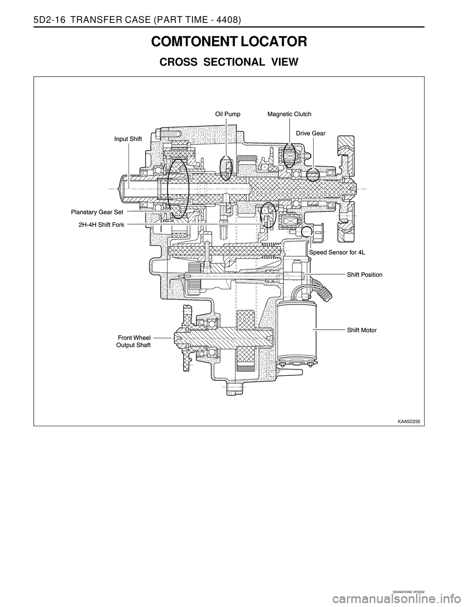
COMTONENT LOCATOR
CROSS SECTIONAL VIEW
KAA5D250
Page 1436 of 2053
TRANSFER CASE (PART TIME - 4408) 5D2-37
SSANGYONG MY2002
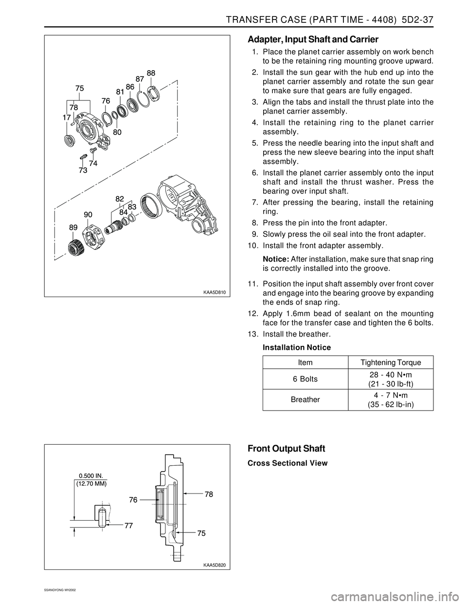
KAA5D810
KAA5D820
Adapter, Input Shaft and Carrier
1. Place the planet carrier assembly on work bench
to be the retaining ring mounting groove upward.
2. Install the sun gear with the hub end up into the
planet carrier assembly and rotate the sun gear
to make sure that gears are fully engaged.
3. Align the tabs and install the thrust plate into the
planet carrier assembly.
4. Install the retaining ring to the planet carrier
assembly.
5. Press the needle bearing into the input shaft and
press the new sleeve bearing into the input shaft
assembly.
6. Install the planet carrier assembly onto the input
shaft and install the thrust washer. Press the
bearing over input shaft.
7. After pressing the bearing, install the retaining
ring.
8. Press the pin into the front adapter.
9. Slowly press the oil seal into the front adapter.
10. Install the front adapter assembly.
Notice: After installation, make sure that snap ring
is correctly installed into the groove.
11. Position the input shaft assembly over front cover
and engage into the bearing groove by expanding
the ends of snap ring.
12. Apply 1.6mm bead of sealant on the mounting
face for the transfer case and tighten the 6 bolts.
13. Install the breather.
Installation Notice
Tightening Torque
28 - 40 Nm
(21 - 30 lb-ft)
4 - 7 Nm
(35 - 62 lb-in)
Item
6 Bolts
Breather
Front Output Shaft
Cross Sectional View
Page 1437 of 2053
SSANGYONG MY2002
5D2-38 TRANSFER CASE (PART TIME - 4408)
KAA5D830
KAA5D840
KAA5D850
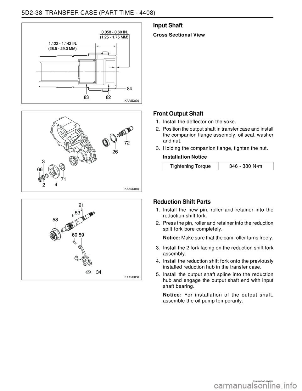
Input Shaft
Cross Sectional View
Tightening Torque346 - 380 Nm
Front Output Shaft
1. Install the deflector on the yoke.
2. Position the output shaft in transfer case and install
the companion flange assembly, oil seal, washer
and nut.
3. Holding the companion flange, tighten the nut.
Installation Notice
Reduction Shift Parts
1. Install the new pin, roller and retainer into the
reduction shift fork.
2. Press the pin, roller and retainer into the reduction
spilt fork bore completely.
Notice: Make sure that the cam roller turns freely.
3. Install the 2 fork facing on the reduction shift fork
assembly.
4. Install the reduction shift fork onto the previously
installed reduction hub in the transfer case.
5. Install the output shaft spline into the reduction
hub and engage the output shaft end with input
shaft bearing.
Notice: For installation of the output shaft,
assemble the oil pump temporarily.
Page 1443 of 2053
SECTION 6A
POWER STEERING SYSTEM
TABLE OF CONTENTS
Description and Operation...................................6A-2
General Description.............................................6A-2
Component Locator.............................................6A-3
Diagnostic Information and Procedures..............6A-4
Power Steering System Pressure Test..................6A-4
Power Steering System Leak Test........................6A-4
Maintenance .........................................................6A-5
Bleeding the Power Steering System....................6A-5
Checking and Adding Fluid..................................6A-5Repair Instructions................................................6A-6
On-Vehicle Service.................................................6A-6
Power Steering Fluid Reservoir.............................6A-6
Power Steering Pump Hoses and Pipes................6A-7
Specifications.......................................................6A-9
General Specification...........................................6A-9
Fastener Tightening Specifications.......................6A-9
Special Tools and Equipment............................ 6A-10
Special Tools Table............................................6A-10
Page 1446 of 2053
SSANGYONG MY2002
6A-4 POWER STEERING SYSTEM
KAA6A020
DIAGNOSTIC INFORMATION AND PROCEDURES
POWER STEERING SYSTEM
PRESSURE TEST
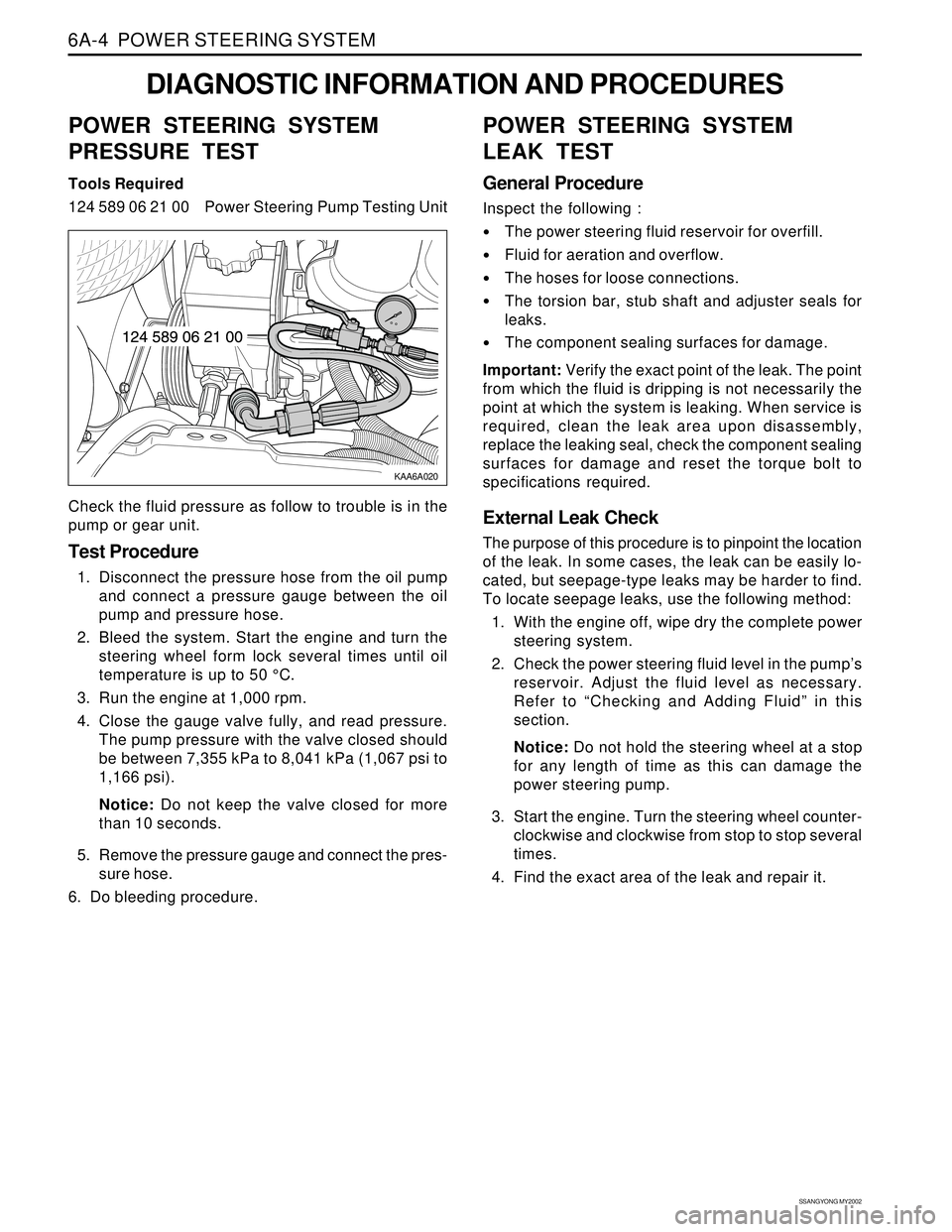
Tools Required
124 589 06 21 00 Power Steering Pump Testing Unit
Check the fluid pressure as follow to trouble is in the
pump or gear unit.
Test Procedure
1. Disconnect the pressure hose from the oil pump
and connect a pressure gauge between the oil
pump and pressure hose.
2. Bleed the system. Start the engine and turn the
steering wheel form lock several times until oil
temperature is up to 50 °C.
3. Run the engine at 1,000 rpm.
4. Close the gauge valve fully, and read pressure.
The pump pressure with the valve closed should
be between 7,355 kPa to 8,041 kPa (1,067 psi to
1,166 psi).
Notice: Do not keep the valve closed for more
than 10 seconds.
5. Remove the pressure gauge and connect the pres-
sure hose.
6. Do bleeding procedure.
POWER STEERING SYSTEM
LEAK TEST
General Procedure
Inspect the following :
The power steering fluid reservoir for overfill.
Fluid for aeration and overflow.
The hoses for loose connections.
The torsion bar, stub shaft and adjuster seals for
leaks.
The component sealing surfaces for damage.
Important: Verify the exact point of the leak. The point
from which the fluid is dripping is not necessarily the
point at which the system is leaking. When service is
required, clean the leak area upon disassembly,
replace the leaking seal, check the component sealing
surfaces for damage and reset the torque bolt to
specifications required.
External Leak Check
The purpose of this procedure is to pinpoint the location
of the leak. In some cases, the leak can be easily lo-
cated, but seepage-type leaks may be harder to find.
To locate seepage leaks, use the following method:
1. With the engine off, wipe dry the complete power
steering system.
2. Check the power steering fluid level in the pump’s
reservoir. Adjust the fluid level as necessary.
Refer to “Checking and Adding Fluid” in this
section.
Notice: Do not hold the steering wheel at a stop
for any length of time as this can damage the
power steering pump.
3. Start the engine. Turn the steering wheel counter-
clockwise and clockwise from stop to stop several
times.
4. Find the exact area of the leak and repair it.
Page 1448 of 2053
SSANGYONG MY2002
6A-6 POWER STEERING SYSTEM
KAA6A040
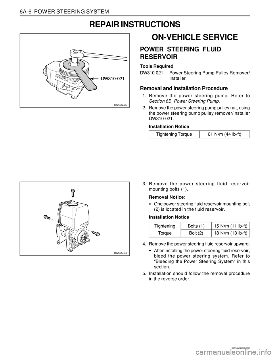
3. Remove the power steering fluid reservoir
mounting bolts (1).
Removal Notice:
One power steering fluid reservoir mounting bolt
(2) is located in the fluid reservoir.
Installation Notice
KAA6A030
ON-VEHICLE SERVICE
POWER STEERING FLUID
RESERVOIR
Tools Required
DW310-021Power Steering Pump Pulley Remover/
Installer
Removal and Installation Procedure
1. Remove the power steering pump. Refer to
Section 6B, Power Steering Pump.
2. Remove the power steering pump pulley nut, using
the power steering pump pulley remover/installer
DW310-021.
Installation Notice
REPAIR INSTRUCTIONS
Tightening Torque 61 Nm (44 lb-ft)
15 Nm (11 lb-ft)
18 Nm (13 lb-ft)
Tightening
TorqueBolts (1)
Bolt (2)
4. Remove the power steering fluid reservoir upward.
After installing the power steering fluid reservoir,
bleed the power steering system. Refer to
“Bleeding the Power Steering System” in this
section.
5. Installation should follow the removal procedure
in the reverse order.