1997 SSANGYONG KORANDO engine
[x] Cancel search: enginePage 1803 of 2053
SECTION 9N
FRAME AND UNDERBODY
TABLE OF CONTENTS
Specifications.......................................................9N-2
Fastener Tightening Specifications.......................9N-2
Underbody Dimensions.......................................9N-3
Maintenance and Repair.....................................9N-7
On-Vehicle Service.................................................9N-7
Alignment Checking............................................9N-7Floor Pan Insulators.............................................9N-7
Engine Under Covers ...........................................9N-8
General Description and System Operation........9N-9
General Body Construction..................................9N-9
Engine Under Covers ...........................................9N-9
Page 1804 of 2053
SSANGYONG MY2002
9N-2 FRAME AND UNDERBODY
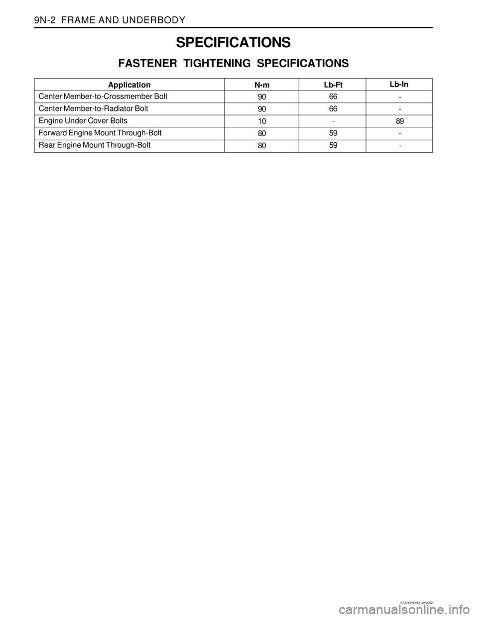
SPECIFICATIONS
FASTENER TIGHTENING SPECIFICATIONS
Center Member-to-Crossmember Bolt
Center Member-to-Radiator Bolt
Engine Under Cover Bolts
Forward Engine Mount Through-Bolt
Rear Engine Mount Through-BoltApplication
N•m
Lb-FtLb-In
90
90
10
80
8066
66
-
59
59-
-
89
-
-
Page 1809 of 2053
FRAME AND UNDERBODY 9N-7
SSANGYONG MY2002
ON-VEHICLE SERVICE
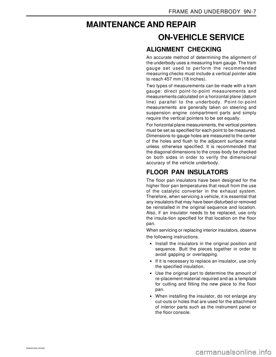
ALIGNMENT CHECKING
An accurate method of determining the alignment of
the underbody uses a measuring tram gauge. The tram
gauge set used to perform the recommended
measuring checks must include a vertical pointer able
to reach 457 mm (18 inches).
Two types of measurements can be made with a tram
gauge: direct point-to-point measurements and
measurements calculated on a horizontal plane (datum
line) parallel to the underbody. Point-to-point
measurements are generally taken on steering and
suspension engine compartment parts and simply
require the vertical pointers to be set equally.
For horizontal plane measurements, the vertical pointers
must be set as specified for each point to be measured.
Dimensions-to-gauge holes are measured to the center
of the holes and flush to the adjacent surface metal
unless otherwise specified. It is recommended that
the diagonal dimensions to the cross-body be checked
on both sides in order to verify the dimensional
accuracy of the vehicle underbody.
FLOOR PAN INSULATORS
The floor pan insulators have been designed for the
higher floor pan temperatures that result from the use
of the catalytic converter in the exhaust system.
Therefore, when servicing a vehicle, it is essential that
any insulators that may have been disturbed or removed
be reinstalled in the original sequence and location.
Also, if an insulator needs to be replaced, use only
the insula-tion specified for that location on the floor
pan.
When servicing or replacing interior insulators, observe
the following instructions.
•Install the insulators in the original position and
sequence. Butt the pieces together in order to
avoid gapping or overlapping.
If it is necessary to replace an insulator, use only
the specified insulation.
Use the original part to determine the amount of
re-placement material required and as a template
for cutting and fitting the new piece to the floor
pan.
When installing the insulator, do not enlarge any
cut-outs or holes that are used for the attachment
of interior parts such as the instrument panel or
the floor console.
MAINTENANCE AND REPAIR
Page 1810 of 2053
SSANGYONG MY2002
9N-8 FRAME AND UNDERBODY
KAA9N040
Route the cross-body harness for interior parts
over the floor pan insulators. Clip it in the original
location.
Do not apply spray-on deadeners or trim
adhesives to the top of the floor pan at the area
directly over the catalytic converter or the muffler.
Any insulator service repair or replacement should be
the same thickness, size, and location as the original
installation in the vehicle.
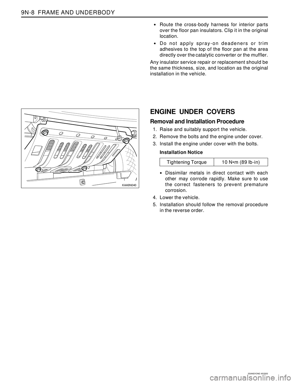
ENGINE UNDER COVERS
Removal and Installation Procedure
1. Raise and suitably support the vehicle.
2. Remove the bolts and the engine under cover.
3. Install the engine under cover with the bolts.
Installation Notice
Dissimilar metals in direct contact with each
other may corrode rapidly. Make sure to use
the correct fasteners to prevent premature
corrosion.
4. Lower the vehicle.
5. Installation should follow the removal procedure
in the reverse order.
Tightening Torque 10 Nm (89 lb-in)
Page 1811 of 2053
FRAME AND UNDERBODY 9N-9
SSANGYONG MY2002
GENERAL DESCRIPTION AND SYSTEM OPERATION
GENERAL BODY CONSTRUCTION
This vehicle is constructed with a unitized body which
in-corporates integral front and rear frame side rails.
The front suspension lower control arms are bolted to
and retained by supports, one each on the right and
left sides. The front suspension lower control arm
supports are attached to the underbody with three bolts
at two locations. The engine is bolted to the integral
front side rails. The suspension strut towers must be
dimensionally correct in relation to the remainder of
the underbody in order to maintain specified
suspension strut and caster/camber angles.
Since the individual underbody parts contribute directly
to the overall strength of the body, it is essential to
observe proper welding techniques during servicerepair operations. The underbody parts should be
properly sealed and rustproofed whenever body repair
operations destroy or damage the original sealing and
rustproofing. When rustproofing critical underbody
parts, use a good-quality type of air-dry primer, such
as a corrosion-resistant chromate or an equivalent
material. Combination-type primer/surfacers are not
recommended.
ENGINE UNDER COVERS
The engine under covers are molded pieces of plastic
that serve as shields for the underside of the engine.
The covers help protect the engine from small rocks,
gravel and other objects that would otherwise come
into contact with the engine during normal driving
conditions.
Page 1837 of 2053
SSANGYONG MY2002
9R-2 BODY FRONT END
DESCRIPTION AND OPERATION
BODY FRONT END
This vehicle has a unitized body with a frame assembly
supporting the engine and the transaxle. The fender
panels and the radiator support are also integral parts
of the body.
Page 1849 of 2053
SSANGYONG MY2002
9T1-2 REMOTE KEYLESS ENTRY AND ANTI-THEFT SYSTEM
DESCRIPTION AND OPERATION
REMOTE KEYLESS ENTRY AND
ANTI-THEFT SYSTEM
The remote keyless entry and anti-theft system can
perform the following functions:
•Remotely lock and unlock the vehicle doors by
means of a hand-held, high-frequency transmitter.
Sense intrusion into the vehicle through the doors
or the hood.
Activate a warning if an intrusion is detected.
Automatically relock the doors if thedoor or the
tail gate is not opened within 30 seconds after the
vehicle has been unlocked by remote keyless
entry.
Help the driver find the vehicle in a parking area.
The remote keyless entry system consist of the
following components:
STICS.
Remote keyless entry system receiver.
Hand-held transmitter.
Tailgate open switch.
Door contact switch.
Siren.
Hood open switch
Key reminder switch.
Antenna.
STICS can perform the following functions:
1. Wiper INT sening vehicle speed.
By operating INT tiem control volume, variable
time will be changed within 1.5-20 seconds
2. Washer relating wiper.
3. Dimming room lamp.
When room lamp is coupled with door, it truns on
if door is opened. After closing the door it
maintains 2 seconds of lighting and dims off
whithin 3 seconds.
4. Time delayed power window control.
Power window can be operated within 30 seconds
after truning the IGN 1 switch from ON to OFF. If
driver/passenger’s door is opened within the 30
seconds from that moment.
5. Rear defogger timer.
The rear defogger will be operated for 12 min. by
turning ON the defogger switch while engine is
running.
Defogger will be stopped by pushing the switch
again.
The defogger will be operated 6 mim, if push ON
the switch within 10 min. after 12 min. of operation.6. Seat belt waring.
The warning lamp will be turned on for about 6
sec. With an intermittent chime bell when the IGN.
Switch is ON unless fastening the seat belt.
7. parking brake warning.
The indicator lamp will flash if drive while the
parking brake is applied.
8. Tail lamp lighting warning.
When the driver’s door is opened while the tail
lamp is still ON, the buzzer operates intermittently.
In this condition, the door will be automatically
unlock when it locked.
9. Door ajar warning.
The indicator lamp will be blinking when the door
is not closed completely and driving.
10. IGN key reminder.
The chime will be operated intermittently if the
driver’s door is opened while the IGN key is still
remain-ing in the ignition switch. In this condition,
the door will be automatically unlocked when it
locked.
11. Central door lock.
All doors will be locked/unlocked by locking/
unlocking the driver’s or passenger’s door.
12. coupled with REKES.
Being coupled with REKES (remote keyless entry
system), all doors will be locked/unlocked
according to signals of transmitter when the
ignition key is not inserted.
13. iginition key hole illumination.
coupled with door switch, ignition key hole
illumination lamp will trun on when the driver ’s
door is opened and will dim off after 10 sec. After
closing the door.
14. Auto door lock.
All doors will be locked automatically if the vehicle
speed reaches 50 km/h though the doors are in
unlock.
15. Auto door unlock.
All doors will be automatically unlock if the vehicle
crashes while driving (over 15km/h).
Operate the burglar alarm.
1. Burglar alarm must operate immediately when the
door, tailgate or hood is opened with improper
ways after all doors and hood were closed and
continued this status for 1 seconds.
2. If the tailgate is opened by key when the system
is on the burglar alarm cindition, the sysem must
be changed to the second burglar alarm condition
frim normal condition.
Page 1858 of 2053
SSANGYONG MY2002
9T2-2 IMMOBILIZER SYSTEM
DESCRIPTION AND OPERATION
Immobilizer is a device disabling vehicle ignition unless
a speific key is used and designed to help prevent
vehicle theft.
Immobilizer is comprised of two devices, a key with
encoded transponder and engine control unit (ECU)
with the same encoding of the transponder. When a
key is inserted into the key hole to start vehicle and
turned to ‘ON’, the ECU reads and decodes the
transponder code and, if the same, starts the engine,
it is called immobilizer. It means immobilizer system
disables starting by stopping fuel supply if the code
in the transponder does not match the code stored in
ECU each other.
Notice:
If vehicle is equipped with immobilizer system and
the engine cranks normally but not start, check
immobilizer system first rather than ignition and
other electrical systems because it can be
disabled fuel supply of injectors by ECU due to
defective immobilizer system.
Programming of the immobilizer system will be
performed by authorized personnel only. If
following defective codes for immobilizer system
appear during diagnosis of vehicle with SCANNER,
ask immobilizer programming to authorized
personnel and actual programming should be
performed by authorized per-sonnel only.
Display of defectives relevant to immobilizer
system : SCANNER
1. No communication with transponder
2. No immobilizer programming
The transponder in the key can be damaged by
shocks of dropping or hitting other objectives, so
handle it with care.
Each supplied key has programming of code on
its own. Accordingly if ECU needs to be replaced,
replace the transponder in the key.
The vehicle equipped with immobilizer system will
never be started with remote ignition device, so
do not attempt to install it.
The immobilizer system will never be removed from
the vehicle. So never attempt to remove it to install
a remote ignition device or others.
If engine does not start during service, use every
key to start the engine and then check immobilizer
sys-tem finally.
Cases that requires immobilizer
programming
1. Replacement ECU
In this case, replace the every transponder of the
key at once.
2. Replacement of the transponder
3. Additional key for lost 1 or 2 keys
1) Clear all codes for current keys from the ECU
2) When using current key : clear code of the trans-
ponder and re-program it
3) Additional (purchased) key : perform programming
4. When lost all keys
1) Clear all memorized key codes from the ECU
2) Replace the key and key set
3) Immobilizer programming