Page 17 of 22
DRIVESHAFTS
General
29
SPECIFICATION
NOTE : the replacement of the NYLSTOP nut with the ENKO driveshaft nut means that the splines of the
stub axles must no longer be coated with
Loctite SCELBLOC.
Vehicle type Engines
GearboxesDriveshaft seal
Left Right
F8Q JB1
D7F JB1
E7J
JB1 / JB3
FC0X
KC0XGE 86 + GI 69GE 86 + RC 462
CONSUMABLES
Type Quantity Component concerned
RHODORSEAL 5661Coat Gearbox side driveshaft roll pin
MOBIL K 575 GS180 g GE 86
ELF GMPT89 or
MOBIL CVJ 825 BLACK STAR110 cm3RC 462
29-1
Page 18 of 22

DRIVESHAFTS
Front driveshafts
REFITTING
Left side :
Fit the driveshaft as horizontally as possible.
Right side :
Coat the splines of the joint on the gearbox side
with
MOLYKOTE BR2 grease.
Fit the driveshaft and check its positioning : an-
gled pin B. Vi. 31-01.
Fit two new roll pins : B. Vi. 31-01. Seal the roll pin
holes using
RHODORSEAL 5661.
On both sides :
Fit the driveshaft stub axle into the hub, it should
go in easily.
Refitting is the reverse of removal. Observe the
tightening torques.
Top up the gearbox oil.
Press the brake pedal several times in order to
bring the piston into contact with the pads.
29
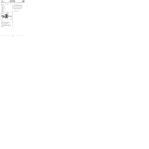
REMOVAL
Vehicle on a two post lift.
Drain the gearbox.
Remove :
- the brake assembly (suspend it from the
chassis),
- the driveshaft nut : tool Rou. 604-01.
Left side :
Remove the three bolts on the gearbox.
Right side :
Remove the roll pin : tool B. Vi. 31-01.
On both sides :
Remove :
- The track rod end nut and extract the shaft :
tool T. Av. 476,
- the upper bolt of the shock absorber base.
Push back the driveshaft : tool T. Av. 1050-02.
Remove the lower bolt of the shock absorber
base and extract the driveshaft.
99544R
SPECIAL TOOLING REQUIRED
B. Vi. 31-01Roll pin punch
Rou. 604-01Hub locking tool
T. Av. 476Ball joint extractor
T. Av. 1050-02Driveshaft extractor
Driveshaft nut 28
Mounting bolt of gaiter on gearbox. 2.5
Wheel bolts 9
Shock absorber base nuts 18
Brake caliper mounting bolts 10
Track rod end nut 3.7
TIGHTENING TORQUES (in daN.m)
29-2
Page 19 of 22

DRIVESHAFTS
Front driveshafts
REFITTING
For its correct positioning on the shaft, the
bearing must be pressed on to obtain a distance
of L = 118 ± 0.2 mm between the rear part of
the bearing and the end of the shaft.
This measurement is obtained using the tool T.
Av. 1331 when its extremity is level with the
shaft.
29
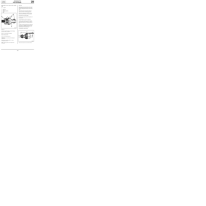
REPLACEMENT OF THE GAITER ON THE GEARBOX
SIDE
GI 69 JOINT
1 Spider
2 Rubber gaiter
3 Bearing guide
4 Retainer
5 Deflector
6 Circlip
7 Driveshaft
85884-1R1
Lefthand
driveshaft
SPECIAL TOOLING REQUIRED
T. Av. 1168 CAILLAU clip pliers
T. Av. 1256 OETIKER crimping pliers
T. Av. 1331 Tool for holding driveshaft bearing gai-
ter in position
DI2935R
REMOVAL
Remove the circlip.
On the press, remove the spider using an
extractor.
NOTE : mark the position of the spider before
extracting it.
Remove the gaiter and deflector - bearing
assembly in the same way as for the spider.
NOTE : in order to avoid deformation of the bea-
ring with a lip seal, and therefore any risk of lea-
kage, do not press it on using a hammer, but using
a press, in order to apply progressive pressure.
The driveshaft is held in the press using the slot
(G) with an extractor.
Replace the spider in the position marked on
removal and refit the retaining circlip.
29-3
Page 20 of 22
DRIVESHAFTS
Front driveshafts
Remove the gaiter and replace with a new one.
Divide the recommended dose of grease
between the gaiter and the stub axle bowl.
NOTE : it is imperative to respect the volume of
grease prescribed in the consumables section.
Position the two beads of the gaiter in the
grooves of the stub axle bowl.
Set the quantity of air in the gaiter.
Fit and tighten the clips.
29
REPLACEMENT OF THE GAITER ON THE WHEEL
SIDE
GE 86 JOINT
1 Stub axle bowl
2 Retaining star
3 Spider
4 Yoke shaft
5 Thermoplastic gaiter
6 Clips
7 Spring
8 Pushrod
9 Shim
10 ABS target
Lefthand
driveshaft
DI2934R
REMOVAL
Join together the two clips (6) taking care not to
damage the grooves of the stub axle bowl.
Remove as much grease as possible.
For the replacement of the thermoplastic gaiter,
it will be necessary to remove the parts on the
gearbox side (GI 69 joint) (see method previously
described).
29-4
Page 21 of 22

DRIVESHAFTS
Front driveshafts
REFITTING
Slightly lubricate the driveshaft in order to facili-
tate the fitting of the gaiter (position the smaller
diameter of the gaiter in the groove of the drives-
haft).
Replace the spider in the position marked on
removal and replace the locking spring ring.
Make three crimping points at 120° by forcing
back the metal of the splines on the driveshaft.
Fit the yoke sleeve onto the spider.
Divide the dose of grease between the gaiter and
the yoke sleeve.
Position the gaiter correctly on its grooves.
Introduce a blunt rod with a rounded edge bet-
ween the gaiter and the yoke sleeve, in order to
measure the quantity of air contained inside the-
joint.
Lengthen or shorten the joint until you obtain the
measurement A = 190 mm (measurement taken
between the end of the joint and the face of the
smaller diameter of the yoke sleeve).
In this position, remove the rod.
29
REPLACEMENT OF THE GAITER ON THE GEARBOX
SIDE
RC 462 JOINT
1 Yoke sleeve
2 Spider
3 Locking spring ring
4 Gaiter
5 Clips
Lefthand
driveshaft
DI2933R
REMOVAL
Cut the two clips (5) taking care not to damage
the groove of the yoke sleeve.
Remove as much grease as possible.
Remove the yoke sleeve
Remove the locking spring ring
IMPORTANT: never use solvent for cleaning the
components.
On the press, extract the spider by using a
releasing type extractor .
NOTE : mark the position of the spider before
extracting it.
90392R1
Refit the clips using the recommended tooling.
29-5
Page 22 of 22

DRIVESHAFTS
Front driveshafts
NOTE : certain righthand driveshafts are fitted
with vibration absorbers; if the thermoplastic gai-
ter is damaged replace the whole driveshaft .
Remove the gaiter and replace with a new one.
Divide the recommended dose of grease between
the gaiter and the stub axle bowl.
NOTE : it is imperative to respect the volume of
grease prescribed in the consumables section.
Position the two beads of the gaiter into the
grooves of the stub axle bowl.
Set the quantity of air in the gaiter.
Fit and tighten the clips.
29
REPLACEMENT OF THE GAITER ON THE WHEEL
SIDE
GE 86 JOINT
1 Stub axle bowl
2 Retaining star
3 Spider
4 Yoke shaft
5 Thermoplastic gaiter
6 Clips
7 Spring
8 Pushrod
9 Shim
10 ABS target
Righthand
driveshaft
DI2934R
REMOVAL
Join together the two clips (6) taking care not to
damage the grooves of the stub axle bowl.
Remove as much grease as possible.
For the replacement of the thermoplastic gaiter,
it will be necessary to remove the parts on the
gearbox side (RC 462 joint) (see method previously
described).
29-6
Page:
< prev 1-8 9-16 17-24