Page 9 of 22
MANUAL GEARBOX
Ratios
21
906
175F/K C0D55
16
JB1
5thVehicleSuffixDifferential
ratio4th3rdSpeedometer
gear1st2ndReverse
gear
19
21171
172
173
174
59
14
35
34
32
39
33
37
39
28
39
1126
57
16
41
11
43
21
168
169F/K C0C59
14
JB3
5thVehicleSuffixDifferential
ratio4th3rdSpeedometer
gear1st2ndReverse
gear
19
21
35
34
32
39
43
21
39
28
39
112614
11
F/K C0A
F/K C0E
31
39
169 for vehicles fitted with Air Conditioning.
21-2
Page 10 of 22
MANUAL GEARBOX
Capacities - Lubricants
CAPACITY (in litres)
21
CHECKING THE LEVEL
Filling is by overflow
5 gear box
JB13.4
JB33.4
Viscosity grade
TRX 75W 80W
92081S
21-3
Page 11 of 22
MECHANICAL GEARBOX
Consumables
21
TYPEPACKAGING
Loctite 518
LOCTITE FRENBLOC
(locking and sealing
resin)
24 ml syringe
100 g tube
24 cc bottle
PART NUMBER
77 01 404 452
77 01 394 071
COMPONENT
77 01 421 162Housing assembling faces
Threaded plugs and switches
Bearing plugs
Ends of roll pins on driveshafts
Primary and secondary shaft nuts
Fixed gear and 5th gear hub
Rear differential lock drive stud
Splines of the right - hand sunwheel
Fork pivot
Thrust bearing guide
Fork pads
MOLYKOTE BR277 01 421 1451 kg tinClutch
Parts to be systematically replaced
After they have been removed :
- the lip seals,
- the O-ring seals,
- the clutch thrust bearing guide tubes,
- the secondary and differential shaft nuts,
- the speedometer drive gear and its shaft,
- the speedometer ring gear,
- the roll pins,
- the gear supporting rings.
RHODORSEAL 5661
Eg : CAF 4/60 THIXO
21-4
Page 12 of 22
MANUAL GEARBOX
Gearbox (removal - refitting)
21
SPECIAL TOOLING REQUIRED
B. Vi. 31-01Set of punches
Mot. 1040-01Engine sub-frame carrier
T. Av. 476Ball joint extractor
Brake calliper bolt 4
Driveshaft gaiter bolt 2.5
Lower ball joint nut 5.5
Shock absorber base bolt 18
Engine tie-bar bolt 6.5
Gearbox edge and starter motor bolt 4.5
Suspended mounting bolt on gearbox 4
Wheel bolts 9
Track rod end nut 4
TIGHTENING TORQUES (In daN.m)
REMOVAL
Place the vehicle onto a two post lift.
Disconnect the battery.
Remove :
- the engine cover,
- the battery.
Disconnect the connectors on:
- the injection computer (petrol version),
- the preheating unit (diesel version),
_ the diesel fuel filter (diesel version),
- the impact sensor.
Remove the air filter sleeve.
13083S
EQUIPMENT REQUIRED
Engine support tool
Component jack
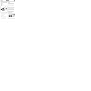
Remove the bolts (A) of the battery protective
screen.
13088R
21-5
Page 13 of 22
MANUAL GEARBOX
Gearbox (Removal - Refitting)
21
Remove :
- the two mounting bolts (B),
13119R
Disconnect the clutch cable.
Remove :
- the upper bolts at the gearbox edge and on
the starter motor (slacken the bolt (D) as far
as possible)
- the earth strap bolts on the gearbox,
- the two bolts of the
TDC sensor.
13097-2R
- the front wheels,
- the oil collector under the gearbox.
On the right-hand side of the vehicle, remove the
driveshaft pins using tool B. Vi. 31-01.
91755-1R2
Remove on both sides :
- the brake callipers and attach them together
- the mudguards,
- the track rod ends (T. Av. 476),
- the shock absorber base bolts,
- the sub-frame side member tie-rods (A),
- the stub axle carrier-driveshaft by disconnec-
ting it from the lower ball joint
99070R1
21-6
Page 14 of 22
MANUAL GEARBOX
Gearbox (Removal - Refitting)
21
Ensure that the rollers of the left driveshaft can-
not be removed by hand. If they can, check if any
of the needles have fallen into the gearbox.
Disconnect and remove the starter motor.
Disconnect:
- the reversing light connector,
- the speedometer connector and remove the
gearbox sensor.
Remove :
- the exhaust downpipe,
- the entire gear control lever by removing the
bolt (E) and the three bolts of the heat shield
for access to the base of the gear lever
- the engine tie-bar bolt,
- the rear support on the gearbox.
12993-1R2
Remove the engine-gearbox tie-rod.
To aid the removal of the steering box, fit, if ne-
cessary, a shim, in order to tilt the engine for-
ward.
Remove the steering box and secure it.
Fit the engine support and take the weight of
the engine and transmission assembly.
Positioning on F8Q engine
13120S
13121S
21-7
Page 15 of 22
MANUAL GEARBOX
Gearbox (Removal - Refitting)
21
Positioning on petrol engines
13122S
Remove the three mounting bolts for the support
on the gearbox.
Remove the engine sub-frame by slackening the
four mounting bolts.
Fit the component jack under the gearbox wi-
thout lifting it.
Separate the gearbox from the engine having re-
moved the nut (E) and the engine-gearbox moun-
ting stud.
98755R1
85812-1R
12924R
Lower the engine as far as possible.
Remove :
- the last gearbox edge bolt at the top,
- the bumper.
Fit the sub-frame support (Mot. 1040-01) and lo-
wer the vehicle.
21-8
Page 16 of 22
MANUAL GEARBOX
Gearbox (Removal - Refitting)
21
REFITTING
Coat the walls of the guide tube and the fork pads
with
MOLIKOTE BR2 grease.
Place the fork onto the slots of the clutch thrust
bearing.
Assemble the gearbox on the engine taking care
not to alter the height of the engine.
Ensure the presence and correct positioning of
the engine- gearbox centering rings .
The presence of the stud (C) aids assembly.
86308R2
Refit:
- the engine sub-frame,
- the steering,
- the exhaust downpipe,
- the engine tie-bar.
SPECIAL NOTE FOR THE E7J ENGINE
Refit the exhaust downpipe before the right-
hand driveshaft.
Refit the other components by proceeding in the
reverse order to removal.
21-9


21
CHECKING THE LEVEL
Filling is by overflow
5 gear box
JB13.4
JB33.4
Viscosity grade
TRX 75W 80W
92081S
21-3")

24 ml syringe
100 g tube
24 cc bottle
PART NUMBER
77 01 404 452
77 01 394 071
COMPONENT")

21
SPECIAL TOOLING REQUIRED
B. Vi. 31-01Set of punches
Mot. 1040-01Engine sub-frame carrier
T. Av. 476Ball joint extractor
Brake calliper bolt")

21
Remove :
- the two mounting bolts (B),
13119R
Disconnect the clutch cable.
Remove :
- the upper bolts at the gearbox edge and on
the starter motor (sl")

21
Ensure that the rollers of the left driveshaft can-
not be removed by hand. If they can, check if any
of the needles have fallen into the gearbox.
Di")

21
Positioning on petrol engines
13122S
Remove the three mounting bolts for the support
on the gearbox.
Remove the engine sub-frame by slackening the
four")

21
REFITTING
Coat the walls of the guide tube and the fork pads
with
MOLIKOTE BR2 grease.
Place the fork onto the slots of the clutch thrust
bearing.
Asse")