Page 28 of 1310

GENERAL ± Precautions Before Service00-25
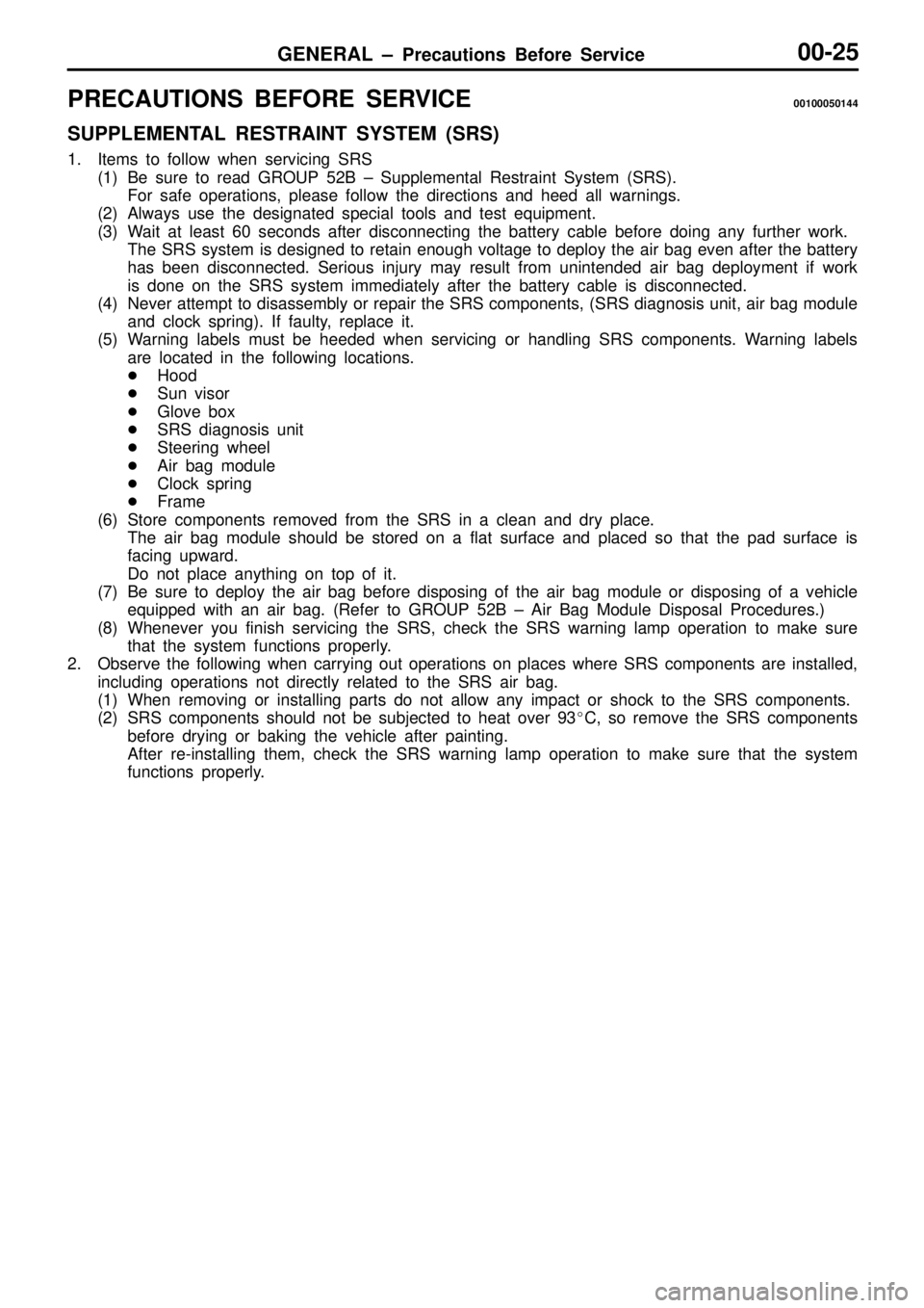
PRECAUTIONS BEFORE SERVICE00100050144
SUPPLEMENTAL RESTRAINT SYSTEM (SRS)
1. Items to follow when servicing SRS
(1) Be sure to read GROUP 52B ± Supplemental Restraint System (SRS).
For safe operations, please follow the directions and heed all warnings.
(2) Always use the designated special tools and test equipment.
(3) Wait at least 60 seconds after disconnecting the battery cable before doing any further work.
The SRS system is designed to retain enough voltage to deploy the air bag even after the battery
has been disconnected. Serious injury may result from unintended air bag deployment if work
is done on the SRS system immediately after the battery cable is disconnected.
(4) Never attempt to disassembly or repair the SRS components, (SRS diagnosis unit, air bag module
and clock spring). If faulty, replace it.
(5) Warning labels must be heeded when servicing or handling SRS components. Warning labels
are located in the following locations.
�Hood
�Sun visor
�Glove box
�SRS diagnosis unit
�Steering wheel
�Air bag module
�Clock spring
�Frame
(6) Store components removed from the SRS in a clean and dry place.
The air bag module should be stored on a flat surface and placed so that the pad surface is
facing upward.
Do not place anything on top of it.
(7) Be sure to deploy the air bag before disposing of the air bag module or disposing of a vehicle
equipped with an air bag. (Refer to GROUP 52B ± Air Bag Module Disposal Procedures.)
(8) Whenever you finish servicing the SRS, check the SRS warning lamp operation to make sure
that the system functions properly.
2. Observe the following when carrying out operations on places where SRS components are installed,
including operations not directly related to the SRS air bag.
(1) When removing or installing parts do not allow any impact or shock to the SRS components.
(2) SRS components should not be subjected to heat over 93�C, so remove the SRS components
before drying or baking the vehicle after painting.
After re-installing them, check the SRS warning lamp operation to make sure that the system
functions properly.
Page 34 of 1310

GENERAL ± Supplemental Restraint System (SRS)00-31
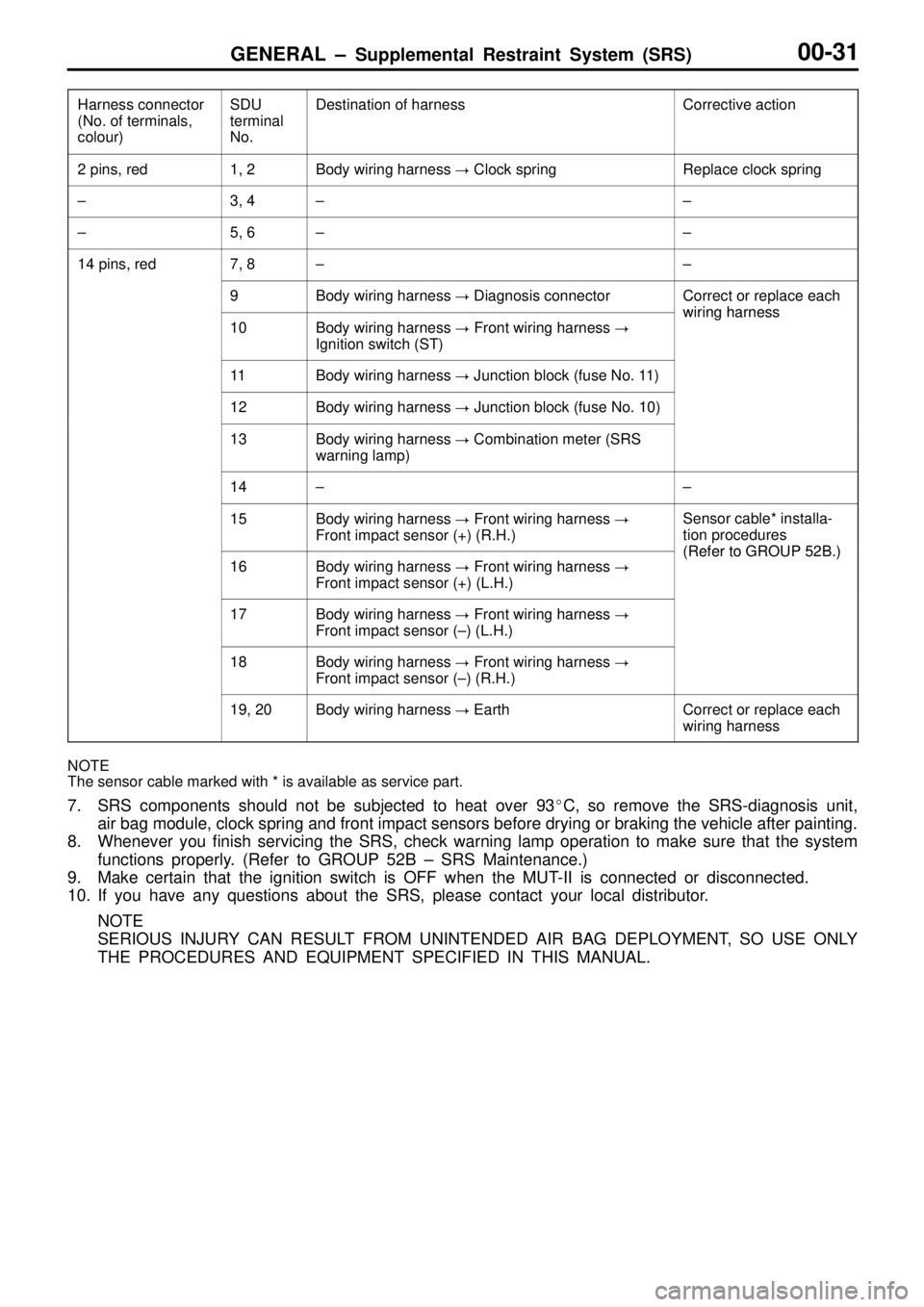
Harness connector
(No. of terminals,
colour)SDU
terminal
No.Destination of harnessCorrective action
2 pins, red1, 2Body wiring harness � Clock springReplace clock spring
±3, 4±±
±5, 6±±
14 pins, red7, 8±±
9Body wiring harness � Diagnosis connectorCorrect or replace each
wiring harness
10Body wiring harness � Front wiring harness �
Ignition switch (ST)
wiring harness
11Body wiring harness � Junction block (fuse No. 11)
12Body wiring harness � Junction block (fuse No. 10)
13Body wiring harness � Combination meter (SRS
warning lamp)
14±±
15Body wiring harness � Front wiring harness �
Front impact sensor (+) (R.H.)Sensor cable* installa-
tion procedures
(Refer to GROUP 52B )16Body wiring harness � Front wiring harness �
Front impact sensor (+) (L.H.)(Refer to GROUP 52B.)
17Body wiring harness � Front wiring harness �
Front impact sensor (±) (L.H.)
18Body wiring harness � Front wiring harness �
Front impact sensor (±) (R.H.)
19, 20Body wiring harness � EarthCorrect or replace each
wiring harness
NOTE
The sensor cable marked with * is available as service part.
7. SRS components should not be subjected to heat over 93�C, so remove the SRS-diagnosis unit,
air bag module, clock spring and front impact sensors before drying or braking the vehicle after painting.
8. Whenever you finish servicing the SRS, check warning lamp operation to make sure that the system
functions properly. (Refer to GROUP 52B ± SRS Maintenance.)
9. Make certain that the ignition switch is OFF when the MUT-II is connected or disconnected.
10. If you have any questions about the SRS, please contact your local distributor.
NOTE
SERIOUS INJURY CAN RESULT FROM UNINTENDED AIR BAG DEPLOYMENT, SO USE ONLY
THE PROCEDURES AND EQUIPMENT SPECIFIED IN THIS MANUAL.
Page 39 of 1310

GENERAL ± Standard Parts-tightening-torque Table00-36
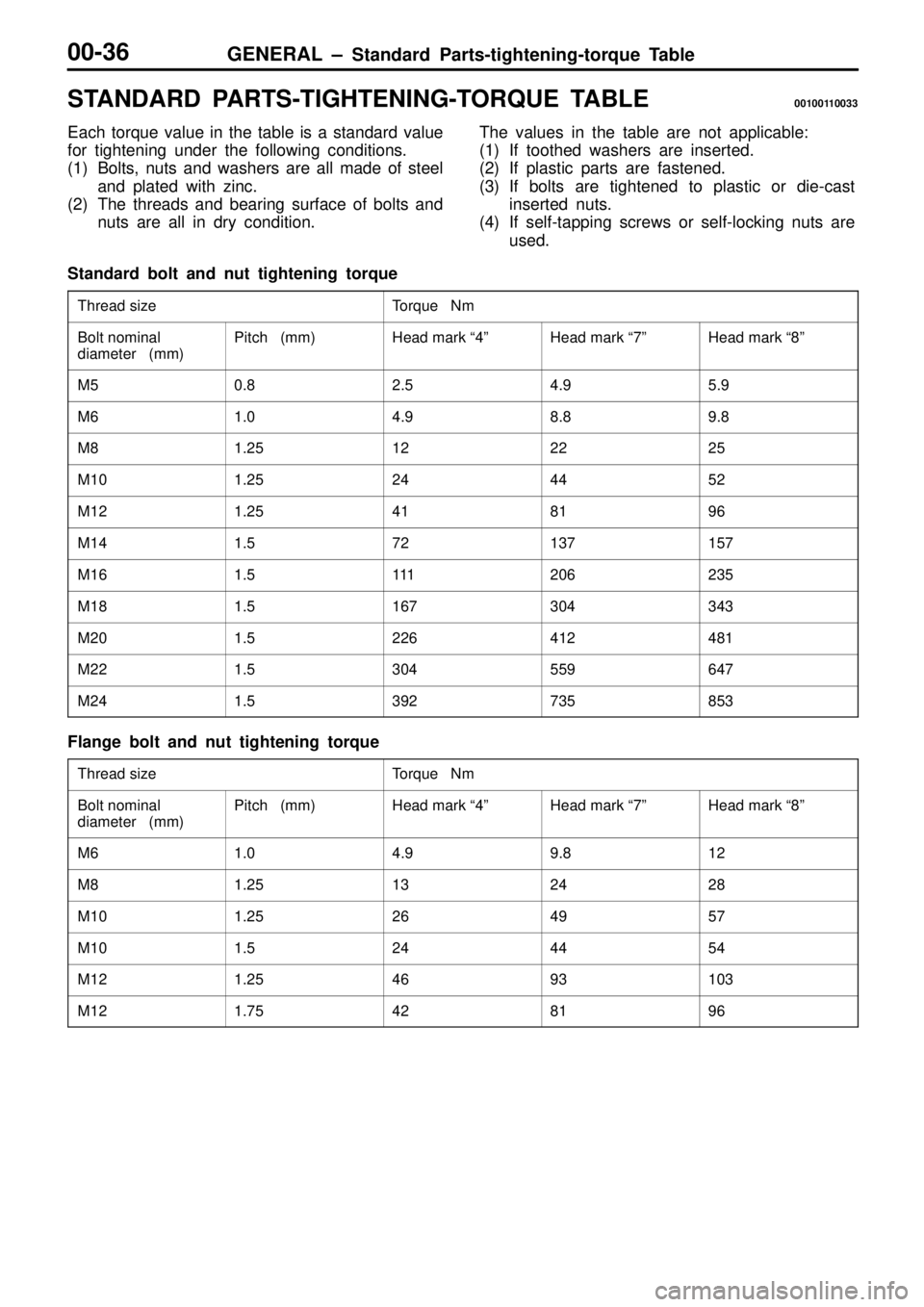
STANDARD PARTS-TIGHTENING-TORQUE TABLE00100110033
Each torque value in the table is a standard value
for tightening under the following conditions.
(1) Bolts, nuts and washers are all made of steel
and plated with zinc.
(2) The threads and bearing surface of bolts and
nuts are all in dry condition.The values in the table are not applicable:
(1) If toothed washers are inserted.
(2) If plastic parts are fastened.
(3) If bolts are tightened to plastic or die-cast
inserted nuts.
(4) If self-tapping screws or self-locking nuts are
used.
Standard bolt and nut tightening torque
Thread sizeTorque Nm
Bolt nominal
diameter (mm)Pitch (mm)Head mark ª4ºHead mark ª7ºHead mark ª8º
M50.82.54.95.9
M61.04.98.89.8
M81.25122225
M101.25244452
M121.25418196
M141.572137157
M161.5111206235
M181.5167304343
M201.5226412481
M221.5304559647
M241.5392735853
Flange bolt and nut tightening torque
Thread sizeTorque Nm
Bolt nominal
diameter (mm)Pitch (mm)Head mark ª4ºHead mark ª7ºHead mark ª8º
M61.04.99.812
M81.25132428
M101.25264957
M101.5244454
M121.254693103
M121.75428196
Page 78 of 1310
ENGINE <4G6> ± Engine Assembly11A-39
REMOVAL SERVICE POINTS
�A�POWER STEERING OIL PUMP ASSEMBLY AND
A/C COMPRESSOR ASSEMBLY REMOVAL
1. Remove the oil pump and A/C compressor (with the hose
attached).
2. Suspend the removed oil pump (by using wire or similar
material) at a place where no damage will be caused
during removal/installation of the engine assembly.
�B�ENGINE ASSEMBLY REMOVAL
1. Check that all cables, hoses, harness connectors, etc.
are disconnected from the engine.
2. Lift the chain block slowly to remove the engine assembly
upward from the engine compartment.
INSTALLATION SERVICE POINT
�A�ENGINE ASSEMBLY INSTALLATION
Install the engine assembly. When doing so, check carefully
that all pipes and hoses are connected, and that none are
twisted, damaged, etc.
Page 114 of 1310
ENGINE <4D5> ± Engine Assembly11B-35
REMOVAL SERVICE POINTS
�A�POWER STEERING OIL PUMP ASSEMBLY AND
A/C COMPRESSOR ASSEMBLY REMOVAL
1. Remove the oil pump and A/C compressor (with the hose
attached).
2. Suspend the removed oil pump (by using wire or similar
material) at a place where no damage will be caused
during removal/installation of the engine assembly.
�B�ENGINE ASSEMBLY REMOVAL
1. Check that all cables, hoses, harness connectors, etc.
are disconnected from the engine.
2. Lift the chain block slowly to remove the engine assembly
upward from the engine compartment.
INSTALLATION SERVICE POINT
�A�ENGINE ASSEMBLY INSTALLATION
Install the engine assembly. When doing so, check carefully
that all pipes and hoses are connected, and that none are
twisted, damaged, etc.
Page 129 of 1310
MPI ± Service Specifications/Sealant13A-6
SERVICE SPECIFICATIONS13100030216
ItemsSpecifications
Basic idle speed r/min750+50
Idle speed when A/C is ON r/min900 at neutral position
Throttle position sensor adjusting voltage mV400 ± 1,000
Throttle position sensor resistance kW3.5 ± 6.5
Idle speed control servo coil resistance W28 ± 33 (at 20�C)
Intake air temperature sensor
resistance kW
20�C2.3 ± 3.0
resistance kW
80�C0.30 ± 0.42
Engine coolant temperature
sensor resistance kW
20�C2.1 ± 2.7
sensor resistance kW
80�C0.26 ± 0.36
Oxygen sensor output voltage V0.6 ± 1.0
Fuel pressure kPaVacuum hose disconnection324 ± 343 at curb idle
Vacuum hose connectionApprox. 265 at curb idle
Injector coil resistance W13 ± 16 (at 20�C)
SEALANT13100050038
ItemSpecified sealantRemark
Engine coolant temperature sensor
threaded portion3M Nut Locking Part No. 4171 or equivalentDrying sealant
Page 241 of 1310

ENGINE COOLING ±
General Information/
Service Specifications/Lubricant/Sealants14-2
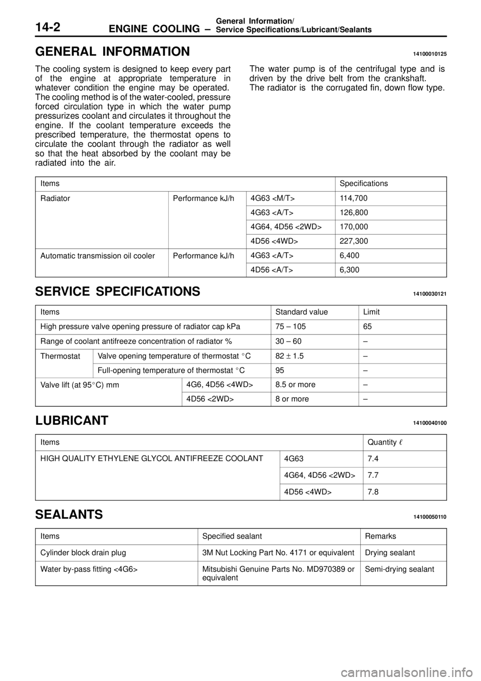
GENERAL INFORMATION14100010125
The cooling system is designed to keep every part
of the engine at appropriate temperature in
whatever condition the engine may be operated.
The cooling method is of the water-cooled, pressure
forced circulation type in which the water pump
pressurizes coolant and circulates it throughout the
engine. If the coolant temperature exceeds the
prescribed temperature, the thermostat opens to
circulate the coolant through the radiator as well
so that the heat absorbed by the coolant may be
radiated into the air.The water pump is of the centrifugal type and is
driven by the drive belt from the crankshaft.
The radiator is the corrugated fin, down flow type.
ItemsSpecifications
RadiatorPerformance kJ/h4G63 114,700
4G63 126,800
4G64, 4D56 <2WD>170,000
4D56 <4WD>227,300
Automatic transmission oil coolerPerformance kJ/h4G63 6,400
4D56 6,300
SERVICE SPECIFICATIONS14100030121
ItemsStandard valueLimit
High pressure valve opening pressure of radiator cap kPa75 ± 10565
Range of coolant antifreeze concentration of radiator %30 ± 60±
ThermostatValve opening temperature of thermostat �C82 + 1.5±
Full-opening temperature of thermostat �C95±
Valve lift (at 95�C) mm4G6, 4D56 <4WD>8.5 or more±
4D56 <2WD>8 or more±
LUBRICANT14100040100
ItemsQuantity �
HIGH QUALITY ETHYLENE GLYCOL ANTIFREEZE COOLANT4G637.4
4G64, 4D56 <2WD>7.7
4D56 <4WD>7.8
SEALANTS14100050110
ItemsSpecified sealantRemarks
Cylinder block drain plug3M Nut Locking Part No. 4171 or equivalentDrying sealant
Water by-pass fitting <4G6>Mitsubishi Genuine Parts No. MD970389 or
equivalentSemi-drying sealant
Page 319 of 1310
ENGINE ELECTRICAL ± Glow System16-44
SERVICE SPECIFICATIONS16400030025
ItemStandard value
Resistance between glow plug plate and glow plug body
(parallel resistance for 4 glow plugs) (at 20 �C) W0.10 ± 0.15
Voltage between glow plug plate and
glow plug body VImmediately after igni-
tion switch is turned to
ON (without starting
the engine)9 ± 11 (Drops to 0 V after 4 ± 8 seconds have passed)
While engine is crank-
ing6 or more
While engine is warm-
ing up12 ± 15 (Drops to 0 V when the engine coolant
temperature increases to 60 �C or more or if 180
seconds have passed since the engine was started)
Glow plug resistance (at 20 �C) W0.4 ± 0.6
SEALANT16400050021
ItemSpecified sealantRemark
Engine coolant temperature sensor3M Nut Locking Part No.4171 or equivalentDrying sealant