1997 MERCEDES-BENZ ML500 rearview
[x] Cancel search: rearviewPage 1778 of 4133

Fig. 186: Identifying Rain Sensor Components
Modification notes
11.4.03Disconnecting ground
lead from battery newly
includedStep 1
Remove/Install
1Disconnect ground
cable of battery AR54.10-P-0003A
2Remove rearview
mirror (1).Models 163.154/172#A up to
145272, Models 163.154/172#X up
to 708318AR68.40-P-0001GH
Models 163.154/172#A as of
145273, Models 163.154/172#X as
of 708319, Models
163.113/128/157/174/175AR68.40-P-0001GI
3Disconnect electrical
connector (2) from
rain sensor(B38)
4Press retaining lugs
(arrows) downward
5Remove rain sensor
(B38) Lens of rain sensor (B38) is
bonded to the windshield and may
2001 Mercedes-Benz ML320
1998-2005 ACCESSORIES & BODY, CAB Electrical System - Body - 163 Chassis
me
Saturday, October 02, 2010 3:30:09 PMPage 283 © 2006 Mitchell Repair Information Company, LLC.
Page 1788 of 4133

Fig. 194: Identifying Microphone Components
REMOVE/INSTALL LOUDSPEAKER AMPLIFIER CONTROL MODULE - AR82.62-P-7720GH
MODELS 163.113 /128 /136 /154 /157 /172 /175 with CODE (810) Sound system
MODEL 163.174
Removal/installation
1Remove inside rearview mirror AR68.40-P-0001GI
2Unclip plug from bracket
3Remove sound amplifier (B25/6)
microphone Do not damage
wiring harness.
Withdraw
microphone from
above.
4Install in the reverse order
5Check sound amplifier
microphone (B25/6) AR82.62-P-1110GH
2001 Mercedes-Benz ML320
1998-2005 ACCESSORIES & BODY, CAB Electrical System - Body - 163 Chassis
me
Saturday, October 02, 2010 3:30:09 PMPage 293 © 2006 Mitchell Repair Information Company, LLC.
Page 2067 of 4133
GF72.29-P-2002GH
Convenience control, function
7.4.97
MODEL
163
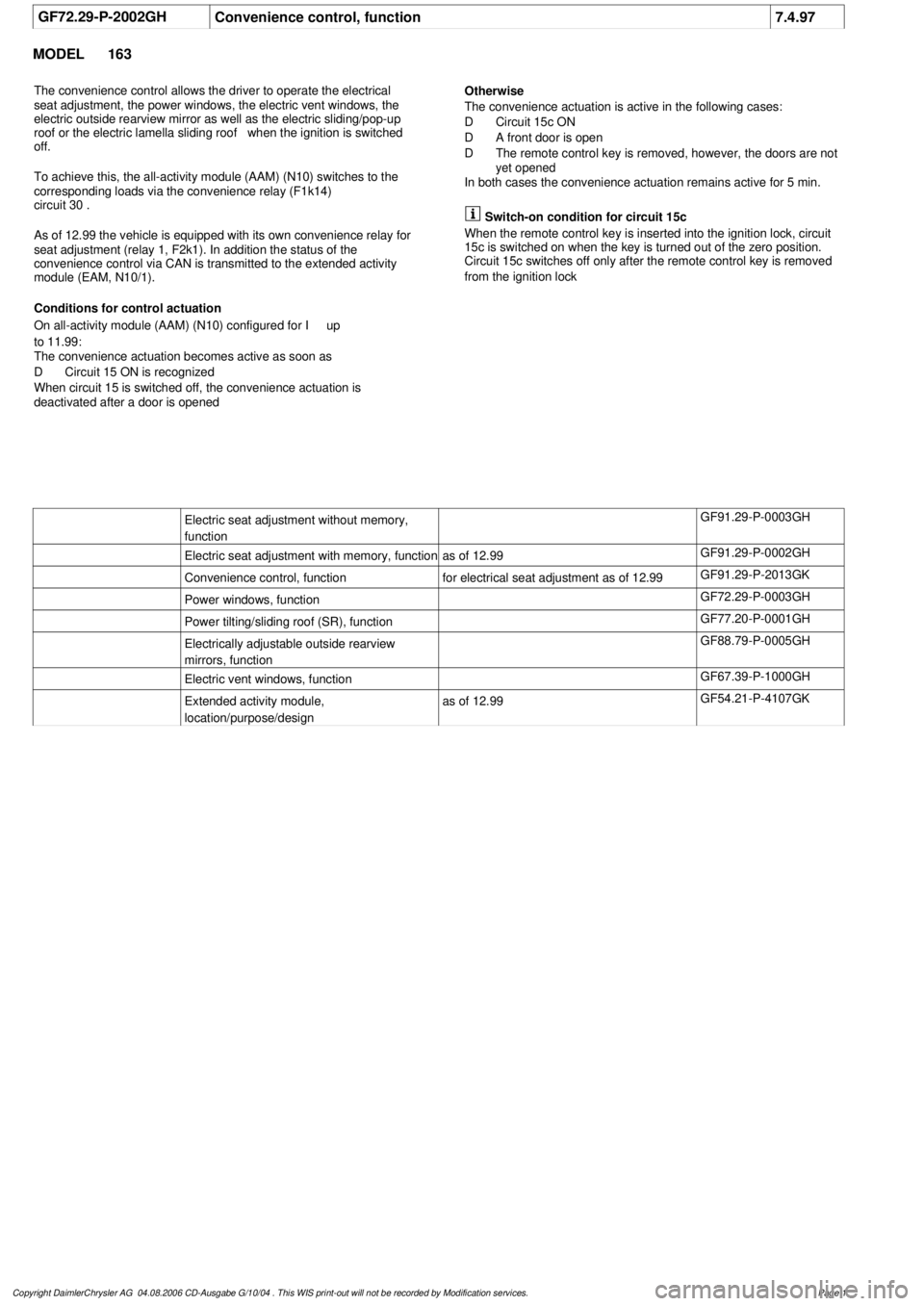
The convenience control allows the driver to operate the electrical
seat adjustment, the power windows, the electric vent windows, the
electric outside rearview mirror as well as the electric sliding/pop-up
roof or the electric lamella sliding roof
when the ignition is switched
off.
To achieve this, the all-activity module (AAM) (N10) switches to the
corresponding loads via the convenience relay (F1k14)
circuit 30 .
As of 12.99 the vehicle is equipped with its own convenience relay for
seat adjustment (relay 1, F2k1). In addition the status of the
convenience control via CAN is transmitted to the extended activity
module (EAM, N10/1).
Conditions for control actuation
On all-activity module (AAM) (N10) configured for
I
up
to
11.99:
The convenience actuation becomes active as soon as
D
Circuit 15 ON is recognized
When circuit 15 is switched off, the convenience actuation is
deactivated after a door is opened
Otherwise
The convenience actuation is active in the following cases:
D
Circuit 15c ON
D
A front door is open
D
The remote control key is removed, however, the doors are not
yet opened
In both cases the convenience actuation remains active for 5 min.
Switch-on condition for circuit 15c
When the remote control key is inserted into the ignition lock, circuit
15c is switched on when the key is turned out of the zero position.
Circuit 15c switches off only after the remote control key is removed
from the ignition lock
Electric seat adjustment without memory,
function
GF91.29-P-0003GH
Electric seat adjustment with memory, function
as of 12.99
GF91.29-P-0002GH
Convenience control, function
for electrical seat adjustment as of 12.99
GF91.29-P-2013GK
Power windows, function
GF72.29-P-0003GH
Power tilting/sliding roof (SR), function
GF77.20-P-0001GH
Electrically adjustable outside rearview
mirrors, function
GF88.79-P-0005GH
Electric vent windows, function
GF67.39-P-1000GH
Extended activity module,
location/purpose/design
as of 12.99
GF54.21-P-4107GK
Copyright DaimlerChrysler AG 04.08.2006 CD-Ausgabe G/10/04 . This WIS print-out will not be recorde
d by Modification services.
Page 1
Page 2119 of 4133

AR88.70-P-9060GH
Removing and installing mirror adjustment motor
12.2.97
MODEL
163
P88.70-0256-04
1
Screw
2
Connector
M21/1
Left electrically adjustable and heated
exterior rearview mirror
M21/2
Right electrically adjustable and
heated exterior rearview mirror (not
illustrated)
Operation no. of operation texts or of standard texts and flat rates
Division
Operation
no.
Operation text
P
883476
REPLACING MOTOR FOR LEFT ELECTRICALLY ADJUSTABLE EXTERIOR REARVIEW MIRROR
P
883478
REPLACING MOTOR FOR RIGHT ELECTRICALLY ADJUSTABLE EXTERIOR REARVIEW MIRROR
Removal, installation
1
Remove covering on outside rearview mirror
Remove mirror housing covering only.
AR88.70-P-9040GH
2
Unscrew screw (1)
3
Disconnect connector (2) and remove mirror
adjustment motor (M21/1 or M21/2)
4
Install in opposite order
Copyright DaimlerChrysler AG 09.05.2006 CD-Ausgabe G/10/04 . This WIS print-out will not be recorde
d by Modification services.
Page 1
Page 2120 of 4133
AR88.70-P-9040GH
Removing and installing outside rearview mirror cover
12.2.97
MODEL
163.113 /136 /154 /172 /174 up to 31.8.01
P88.70-0255-06
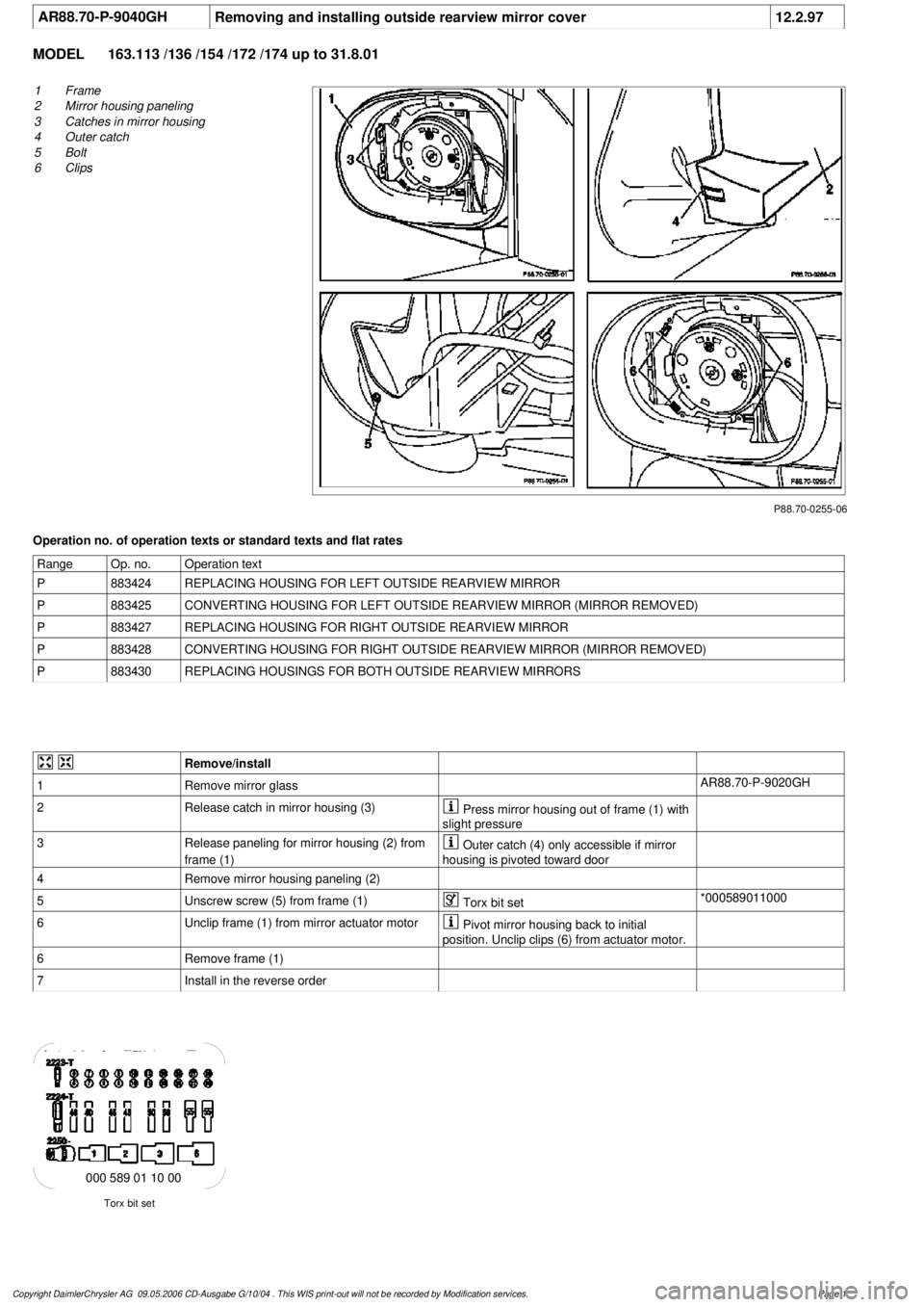
1
Frame
2
Mirror housing paneling
3
Catches in mirror housing
4
Outer catch
5
Bolt
6
Clips
Operation no. of operation texts or standard texts and flat rates
Range
Op. no.
Operation text
P
883424
REPLACING HOUSING FOR LEFT OUTSIDE REARVIEW MIRROR
P
883425
CONVERTING HOUSING FOR LEFT OUTSIDE REARVIEW MIRROR (MIRROR REMOVED)
P
883427
REPLACING HOUSING FOR RIGHT OUTSIDE REARVIEW MIRROR
P
883428
CONVERTING HOUSING FOR RIGHT OUTSIDE REARVIEW MIRROR (MIRROR REMOVED)
P
883430
REPLACING HOUSINGS FOR BOTH OUTSIDE REARVIEW MIRRORS
Remove/install
1
Remove mirror glass
AR88.70-P-9020GH
2
Release catch in mirror housing (3)
Press mirror housing out of frame (1) with
slight pressure
3
Release paneling for mirror housing (2) from
frame (1)
Outer catch (4) only accessible if mirror
housing is pivoted toward door
4
Remove mirror housing paneling (2)
5
Unscrew screw (5) from frame (1)
Torx bit set
*000589011000
6
Unclip frame (1) from mirror actuator motor
Pivot mirror housing back to initial
position. Unclip clips (6) from actuator motor.
6
Remove frame (1)
7
Install in the reverse order
Torx bit set
000 589 01 10 00
Copyright DaimlerChrysler AG 09.05.2006 CD-Ausgabe G/10/04 . This WIS print-out will not be recorde
d by Modification services.
Page 1
Page 2121 of 4133

AR88.70-P-9020GH
Removing and installing mirror glass
12.2.97
MODEL
163.113 /136 /154 /172 /174 up to 31.8.01
P88.70-0253-01
1
Mirror glass
2
Support spring
3
Connector
Arrows
Mirror glass mount
M21/1r1
Mirror heater
M21/2r1
Mirror heater (not illustrated)
P88.70-0254-01
Operation no. of operation texts or standard texts and flat rates
Range
Op. no.
Operation text
P
883321
REPLACING GLASS FOR LEFT OUTSIDE REARVIEW MIRROR
P
883330
REPLACING GLASS FOR RIGHT OUTSIDE REARVIEW MIRROR
P
883340
REPLACING GLASS FOR BOTH OUTSIDE REARVIEW MIRRORS
Remove/install
1
Tilt mirror glass (1) at top outward
Actuate electrical mirror adjustment switch
2
Press mirror glass (1) off of drive
*110589035900
3
Disconnect connector (3) from mirror heater
(M21/1r1 and M21/2r1)
4
Remove mirror glass (1)
Installation:
Install mirror glass (1) from
bottom to top, thereby observe support spring
(2) and mirror glass mounts (arrows).
5
Install in the reverse order
Assembly wedge
110 589 03 59 00
Copyright DaimlerChrysler AG 09.05.2006 CD-Ausgabe G/10/04 . This WIS print-out will not be recorde
d by Modification services.
Page 1
Page 2122 of 4133

AR88.70-P-9000GH
Remove/install complete outside rearview mirror
12.2.97
MODEL
163.113 /128 /136 /154 /157 /172 /174 /175
P88.70-0252-06
Illustrated up to VIN A289564, X754619
1
Paneling
2
Screw
3
Nuts
M21/1
Left electrically adjustable and
heated outside mirror
M21/1x1
Left electrically adjustable and
heated outside mirror connector
Removing and installing
1
Press off paneling (1) with assembly wedge
As of VIN A289565, X754620: If present,
disconnect connector from loudspeaker.
Assembly wedge
*110589035900
2
Unscrew screw (2)
3
Unscrew nut (3)
Secure outside rearview mirror against
falling down
Installation:
Up to VIN A289564,
X754619 fasten mounting lug for connector
for left electrically adjustable and heated
outside rearview mirror (M21/1x1) or for
connector for right electrically adjustable and
heated outside rearview mirror on bottom stud
bolt.
4
Separate connector for left electrically
adjustable and heated outside rearview mirror
(M21/1x1) or connector for right electrically
adjustable and heated outside rearview mirror.
5
Remove left electrically adjustable and heated
outside rearview mirror (M21/1) or right
electrically adjustable and heated outside
rearview mirror
6
Install in the reverse order
Assembly wedge
110 589 03 59 00
Copyright DaimlerChrysler AG 09.05.2006 CD-Ausgabe G/10/04 . This WIS print-out will not be recorde
d by Modification services.
Page 1
Page 2139 of 4133
GF54.21-P-4106-01GH
Extended Activity Module - Task
n
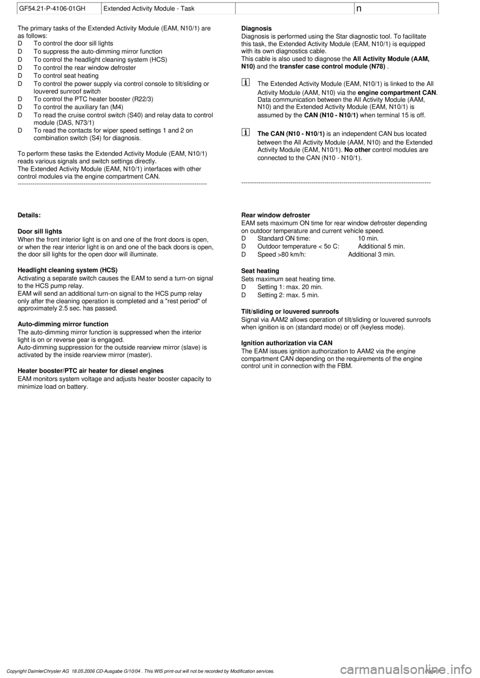
The primary tasks of the Extended Activity Module (EAM, N10/1) are
as follows:
D
To control the door sill lights
D
To suppress the auto-dimming mirror function
D
To control the headlight cleaning system (HCS)
D
To control the rear window defroster
D
To control seat heating
D
To control the power supply via control console to tilt/sliding or
louvered sunroof switch
D
To control the PTC heater booster (R22/3)
D
To control the auxiliary fan (M4)
D
To read the cruise control switch (S40) and relay data to control
module (DAS, N73/1)
D
To read the contacts for wiper speed settings 1 and 2 on
combination switch (S4) for diagnosis.
To perform these tasks the Extended Activity Module (EAM, N10/1)
reads various signals and switch settings directly.
The Extended Activity Module (EAM, N10/1) interfaces with other
control modules via the engine compartment CAN.
-----------------------------------------------------------------------------------------
Diagnosis
Diagnosis is performed using the Star diagnostic tool. To facilitate
this task, the Extended Activity Module (EAM, N10/1) is equipped
with its own diagnostics cable.
This cable is also used to diagnose the
All Activity Module (AAM,
N10)
and the
transfer case control module (N78)
.
The Extended Activity Module (EAM, N10/1) is linked to the All
Activity Module (AAM, N10) via the
engine compartment CAN
.
Data communication between the All Activity Module (AAM,
N10) and the Extended Activity Module (EAM, N10/1) is
assumed by the
CAN (N10 - N10/1)
when terminal 15 is off.
The CAN (N10 - N10/1)
is an independent CAN bus located
between the All Activity Module (AAM, N10) and the Extended
Activity Module (EAM, N10/1).
No other
control modules are
connected to the CAN (N10 - N10/1).
-----------------------------------------------------------------------------------------
Details:
Door sill lights
When the front interior light is on and one of the front doors is open,
or when the rear interior light is on and one of the back doors is open,
the door sill lights for the open door will illuminate.
Headlight cleaning system (HCS)
Activating a separate switch causes the EAM to send a turn-on signal
to the HCS pump relay.
EAM will send an additional turn-on signal to the HCS pump relay
only after the cleaning operation is completed and a "rest period" of
approximately 2.5 sec. has passed.
Auto-dimming mirror function
The auto-dimming mirror function is suppressed when the interior
light is on or reverse gear is engaged.
Auto-dimming suppression for the outside rearview mirror (slave) is
activated by the inside rearview mirror (master).
Heater booster/PTC air heater for diesel engines
EAM monitors system voltage and adjusts heater booster capacity to
minimize load on battery.
Rear window defroster
EAM sets maximum ON time for rear window defroster depending
on outdoor temperature and current vehicle speed.
D
Standard ON time:
10 min.
D
Outdoor temperature < 5
o
C:
Additional 5 min.
D
Speed >80 km/h:
Additional 3 min.
Seat heating
Sets maximum seat heating time.
D
Setting 1: max. 20 min.
D
Setting 2: max. 5 min.
Tilt/sliding or louvered sunroofs
Signal via AAM2 allows operation of tilt/sliding or louvered sunroofs
when ignition is on (standard mode) or off (keyless mode).
Ignition authorization via CAN
The EAM issues ignition authorization to AAM2 via the engine
compartment CAN depending on the requirements of the engine
control unit in connection with the FBM.
Copyright DaimlerChrysler AG 18.05.2006 CD-Ausgabe G/10/04 . This WIS print-out will not be recorde
d by Modification services.
Page 1