1997 MERCEDES-BENZ ML500 dimensions
[x] Cancel search: dimensionsPage 2923 of 4133
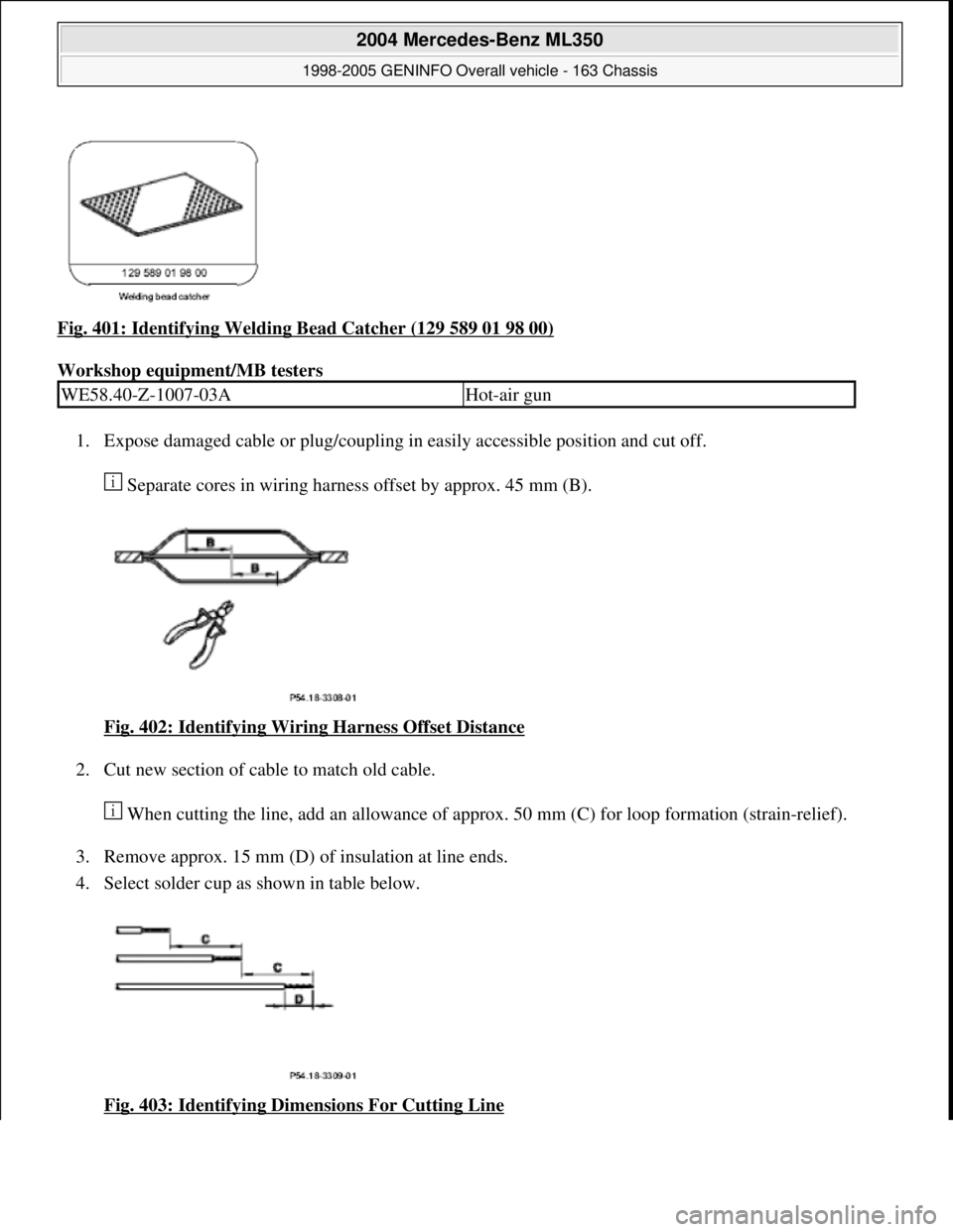
Fig. 401: Identifying Welding Bead Catcher (129 589 01 98 00)
Workshop equipment/MB testers
1. Expose damaged cable or plug/coupling in easily accessible position and cut off.
Separate cores in wiring harness offset by approx. 45 mm (B).
Fig. 402: Identifying Wiring Harness Offset Distance
2. Cut new section of cable to match old cable.
When cutting the line, add an allowance of approx. 50 mm (C) for loop formation (strain-relief).
3. Remove approx. 15 mm (D) of insulation at line ends.
4. Select solder cup as shown in table below.
Fig. 403: Identifying Dimensions For Cutting Line
WE58.40-Z-1007-03AHot-air gun
2004 Mercedes-Benz ML350
1998-2005 GENINFO Overall vehicle - 163 Chassis
me
Saturday, October 02, 2010 3:47:49 PMPage 278 © 2006 Mitchell Repair Information Company, LLC.
Page 3194 of 4133
15
Adjust gap dimensions
Gap dimensions
*BE60.00-P-1001-01D
Feeler gage
*129589032100
16
Align engine hood catch upper section (5)
centered in longitudinal and transverse
direction to engine hood catch lower section
and tighten
*BA88.40-P-1004-01C
17
Ensure that engine hood catch catches
properly
For this purpose, close engine hood and
pull upward with a jerk.
18
Release engine hood and ensure that safety
hook catches on radiator crossmember
19
Close engine hood (2)
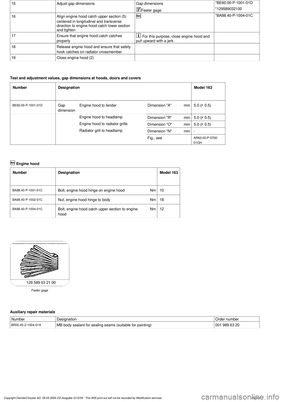
Test and adjustment values, gap dimensions at hoods, doors and covers
Number
Designation
Model 163
BE60.00-P-1001-01D
Gap
dimension
Engine hood to fender
Dimension "A"
mm
5.0 (
F
0.5)
Engine hood to headlamp
Dimension "R"
mm
5.0 (
F
0.5)
Engine hood to radiator grille
Dimension "O"
mm
5.0 (
F
0.5)
Radiator grill to headlamp
Dimension "N"
mm
-
Fig., see
AR60.00-P-0700-
01GH
Engine hood
Number
Designation
Model 163
BA88.40-P-1001-01C
Bolt, engine hood hinge on engine hood
Nm
10
BA88.40-P-1002-01C
Nut, engine hood hinge to body
Nm
18
BA88.40-P-1004-01C
Bolt, engine hood catch upper section to engine
hood
Nm
12
129 589 03 21 00
Feeler gage
Auxiliary repair materials
Number
Designation
Order number
BR00.45-Z-1004-01A
MB body sealant for sealing seams (suitable for painting)
001 989 63 20
Copyright DaimlerChrysler AG 09.05.2006 CD-Ausgabe G/10/04 . This WIS print-out will not be recorde
d by Modification services.
Page 2
Page 3196 of 4133
15
Adjust gap dimensions
Gap dimensions
*BE60.00-P-1001-01D
Feeler gage
*129589032100
16
Align engine hood catch upper section (5)
centered in longitudinal and transverse
direction to engine hood catch lower section
and tighten
*BA88.40-P-1004-01C
17
Ensure that engine hood catch catches
properly
For this purpose, close engine hood and
pull upward with a jerk.
18
Release engine hood and ensure that safety
hook catches on radiator crossmember
19
Close engine hood (2)
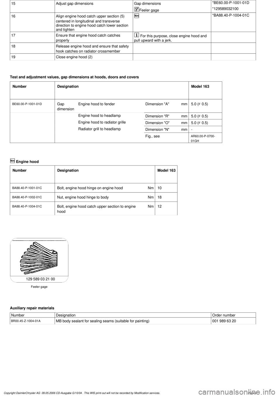
Test and adjustment values, gap dimensions at hoods, doors and covers
Number
Designation
Model 163
BE60.00-P-1001-01D
Gap
dimension
Engine hood to fender
Dimension "A"
mm
5.0 (
F
0.5)
Engine hood to headlamp
Dimension "R"
mm
5.0 (
F
0.5)
Engine hood to radiator grille
Dimension "O"
mm
5.0 (
F
0.5)
Radiator grill to headlamp
Dimension "N"
mm
-
Fig., see
AR60.00-P-0700-
01GH
Engine hood
Number
Designation
Model 163
BA88.40-P-1001-01C
Bolt, engine hood hinge on engine hood
Nm
10
BA88.40-P-1002-01C
Nut, engine hood hinge to body
Nm
18
BA88.40-P-1004-01C
Bolt, engine hood catch upper section to engine
hood
Nm
12
129 589 03 21 00
Feeler gage
Auxiliary repair materials
Number
Designation
Order number
BR00.45-Z-1004-01A
MB body sealant for sealing seams (suitable for painting)
001 989 63 20
Copyright DaimlerChrysler AG 09.05.2006 CD-Ausgabe G/10/04 . This WIS print-out will not be recorde
d by Modification services.
Page 2
Page 3201 of 4133
Danger!
Risk of explosion
from explosive gas.
Risk
of poisoning and caustic burns from
swallowing battery electrolyte.
Risk of injury
through burns to skin and eyes from battery
acid or when handling damaged lead-acid
batteries
No fire, sparks, naked flames or smoking.
Wear protective gloves, acid-resistant
clothing and safety glasses. Pour battery
electrolyte only into suitable and appropriately
marked containers.
AS54.10-Z-0001-01A
4
Remove battery
AR54.10-P-0005GH
5
Press out template (6) and adapt the size to
the correct dimensions (a, b)Determine ACTUAL dimension (a) from the
drawing.
Divide the SPECIFIED dimension (a) by the
determined ACTUAL dimension (a) and copy
the template to the original size with the
corresponding factor.
Check dimensions for both axles.
6
Cut out template
7
Cut out holes (7, 8) for engine hood hinge
studs
8
Position template in the engine hood hinge
support using the stud holes
The template is drawn for the left side.
Turn over to obtain the right side.
9
Center the engine hood hinge support on the
template using the markings (9, 10, 11)
10
Remove template
11
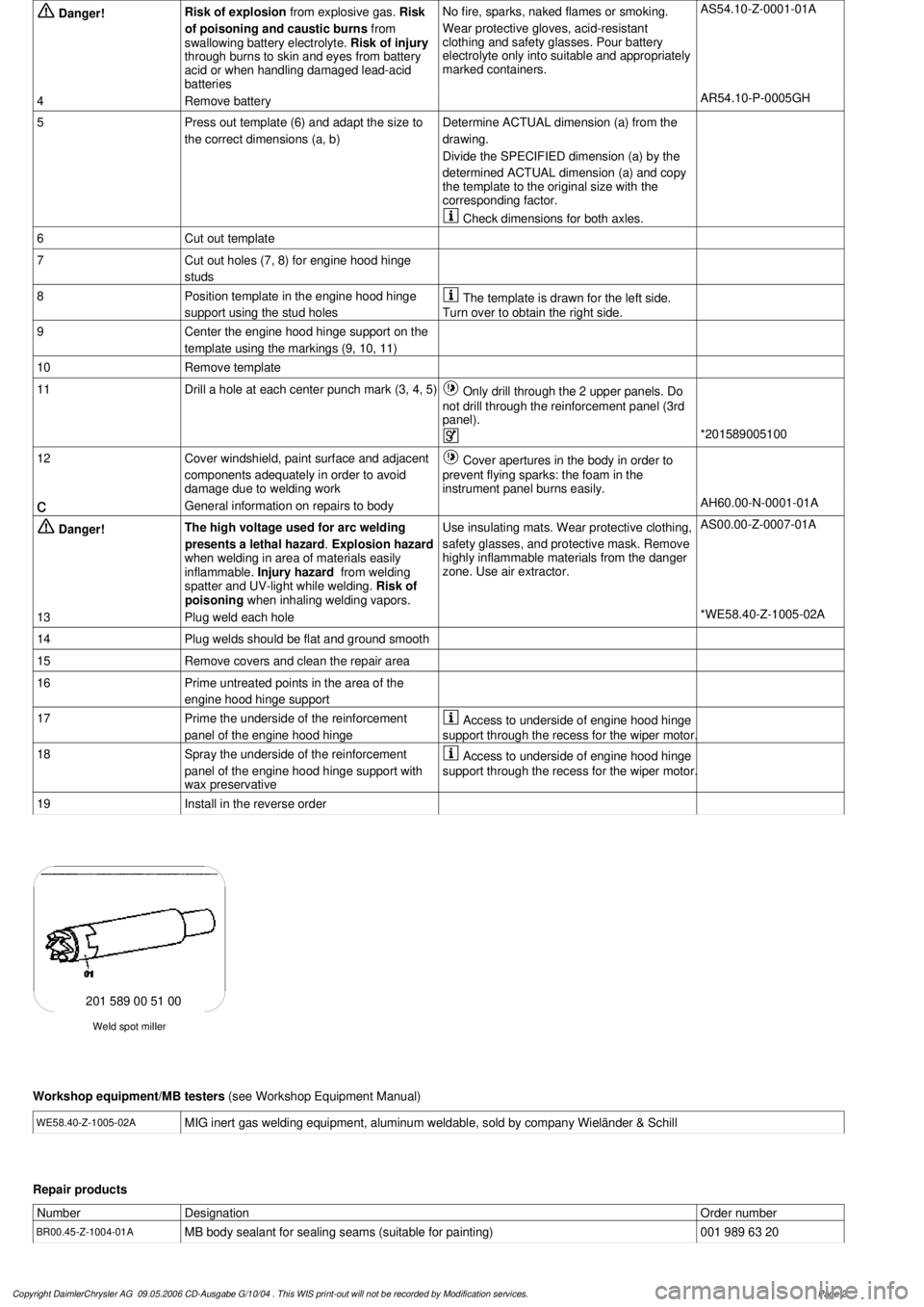
Drill a hole at each center punch mark (3, 4, 5)
Only drill through the 2 upper panels. Do
not drill through the reinforcement panel (3rd
panel).
*201589005100
12
Cover windshield, paint surface and adjacent
components adequately in order to avoid
damage due to welding work
Cover apertures in the body in order to
prevent flying sparks: the foam in the
instrument panel burns easily.
c
General information on repairs to body
AH60.00-N-0001-01A
Danger!
The high voltage used for arc welding
presents a lethal hazard
.
Explosion hazard
when welding in area of materials easily
inflammable.
Injury hazard
from welding
spatter and UV-light while welding.
Risk of
poisoning
when inhaling welding vapors.
Use insulating mats. Wear protective clothing,
safety glasses, and protective mask.
Remove
highly inflammable materials from the danger
zone. Use air extractor.
AS00.00-Z-0007-01A
13
Plug weld each hole
*WE58.40-Z-1005-02A
14
Plug welds should be flat and ground smooth
15
Remove covers and clean the repair area
16
Prime untreated points in the area of the
engine hood hinge support
17
Prime the underside of the reinforcement
panel of the engine hood hinge
Access to underside of engine hood hinge
support through the recess for the wiper motor.
18
Spray the underside of the reinforcement
panel of the engine hood hinge support with
wax preservative
Access to underside of engine hood hinge
support through the recess for the wiper motor.
19
Install in the reverse order
Weld spot miller
201 589 00 51 00
Workshop equipment/MB testers
(see Workshop Equipment Manual)
WE58.40-Z-1005-02A
MIG inert gas welding equipment, aluminum weldable, sold by company Wieländer & Schill
Repair products
Number
Designation
Order number
BR00.45-Z-1004-01A
MB body sealant for sealing seams (suitable for painting)
001 989 63 20
Copyright DaimlerChrysler AG 09.05.2006 CD-Ausgabe G/10/04 . This WIS print-out will not be recorde
d by Modification services.
Page 2
Page 3204 of 4133
3
Remove engine hood hinge on the front
passenger side
AR88.40-P-3060GH
*BR00.45-Z-1004-01A
Danger!
Risk of explosion
from explosive gas.
Risk
of poisoning and caustic burns from
swallowing battery electrolyte.
Risk of injury
through burns to skin and eyes from battery
acid or when handling damaged lead-acid
batteries
No fire, sparks, naked flames or smoking.
Wear protective gloves, acid-resistant
clothing and safety glasses. Pour battery
electrolyte only into suitable and appropriately
marked containers.
AS54.10-Z-0001-01A
4
Remove battery
AR54.10-P-0005GH
5
Remove air conditioning blower motor
AR83.30-P-5560GH
6
Print out template (6) and adapt the size to
the correct dimensions (a, b)Determine ACTUAL dimension (a) from the
drawing.
Divide the SPECIFIED dimension (a) by the
determined ACTUAL dimension (a) and copy
the template to the original size with the
corresponding factor.
Check dimensions for both axles.
7
Cut out template
8
Cut out holes (7, 8) for engine hood hinge
studs
9
Position template in the engine hood hinge
support using the stud holes
The template is drawn for the left side.
Turn over to obtain the right side.
10
Center the engine hood hinge support on the
template using the markings (9, 10, 11)
11
Remove template
12
Drill a hole at each center punch mark (3, 4, 5)
Only drill through the 2 upper panels. Do
not drill through the reinforcement panel (3rd
panel).
*201589005100
13
Cover windshield, paint surface and adjacent
components adequately in order to avoid
damage due to welding work
Cover apertures in the body in order to
prevent flying sparks: the foam in the
instrument panel burns easily.
c
General information on repairs to body
AH60.00-N-0001-01A
Danger!
The high voltage used for arc welding
presents a lethal hazard
.
Explosion hazard
when welding in area of materials easily
inflammable.
Injury hazard
from welding
spatter and UV-light while welding.
Risk of
poisoning
when inhaling welding vapors.
Use insulating mats. Wear protective clothing,
safety glasses, and protective mask.
Remove
highly inflammable materials from the danger
zone. Use air extractor.
AS00.00-Z-0007-01A
14
Plug weld each hole
*WE58.40-Z-1005-02A
15
Plug welds should be flat and ground smooth
16
Remove covers and clean the repair area
17
Prime untreated points in the area of the
engine hood hinge support
18
Prime the underside of the reinforcement
panel of the engine hood hinge
Access to underside of engine hood hinge
support through the recess for the wiper motor.
19
Spray the underside of the reinforcement
panel of the engine hood hinge support with
wax preservative
Access to underside of engine hood hinge
support through the recess for the wiper motor.
20
Install in the reverse order
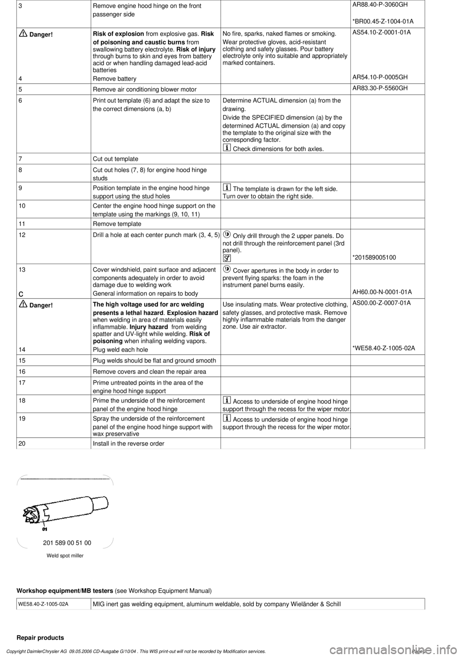
Weld spot miller
201 589 00 51 00
Workshop equipment/MB testers
(see Workshop Equipment Manual)
WE58.40-Z-1005-02A
MIG inert gas welding equipment, aluminum weldable, sold by company Wieländer & Schill
Repair products
Copyright DaimlerChrysler AG 09.05.2006 CD-Ausgabe G/10/04 . This WIS print-out will not be recorde
d by Modification services.
Page 2
Page 3484 of 4133

AH40.10-P-9411-01A
Information on tires/rims
Model 124, 129, 140, 163, 168, 169,
170, 171, 199, 201, 202, 203, 208, 209,
210, 211, 215, 219, 220, 230, 240, 414,
450, 452,
639
Tires
D
For service conversions, the tire/disc wheel specifications and
dimensions should be compared with the entries in the
registration papers.
D
When mounting tires, the tires and rims must be carefully
matched in order to guarantee the concentricity of the wheel.
Identification of matching points on:
- Tires with a colored dot on the outside of the tire,
- Sheet steel disk wheel by a colored dot or punch mark on the
outside of the wheel,
- Perform this operation at the valve stem hole on light-alloy
disk wheels
With an additional paint spot or punch mark in the rim base
for the 140 Model Series.
D
Always replace the rubber valve.
-----------------------------------------------------------------------------------------
D
Damaged and defective tires must always be replaced. The
repair methods employed in the tire trade are not approved by
Mercedes-Benz. Small nicks (<0.8mm) on the tire's sidewall do
not usually pose a cause for concern, and continued use of
such tires is approved
D When replacing just one tire, install it on the front of the vehicle.
This does not apply to vehicles with different tires of varying
specifications on the front and rear wheels.
D
Only use tires listed in the valid Service Information bulletins
and repair instructions.
D
If the permissible maximum speed of an M+S tire is below the
maximum speed of the vehicle, an appropriate adhesive plate
must be attached in the driver's field of view.
-----------------------------------------------------------------------------------------
D
Tires permissible for higher speeds may be used.
D
Always fit all rims with tires of the same design, make and
version.
-----------------------------------------------------------------------------------------
D
Run in new tires for approx. 100 km at moderate speed.
D
Handed tires must be installed according to the arrow on the
side wall of the tire.
D
Tires are subject to an aging process with negative effects on
the properties of the tire. In order to ensure optimum
effectiveness in winter, M+S tires should not be used for longer
than 3 years.
-----------------------------------------------------------------------------------------
Tire pressure
(For specified values see tire pressure table in the fuel filler flap, on
the Vaneo BM 414 see B-pillar on the passenger side).
Too low tire pressure increases the rolling resistance and increases
the flexing energy of the tire. This causes the critical temperature limit
to be exceeded (carcass detachment) and destroys the tire. Respond
to loss of tire pressure by determining the source and replacing the
tire as indicated.
Cleaning
Using a spray wand with high-pressure nozzles to clean the wheel
can lead to tire damage. Such damage occurs especially on the tire
side walls. The following should be observed when using flat jet
nozzles:
D
Maintain a minimum distance of 300 mm
D
Do not direct the water jet at a single point on the surface of the
tire for any length of time.
-----------------------------------------------------------------------------------------
Mounting in bearings
Before putting into storage, clean tires thoroughly and check for
damage and adequate tread depth. Mark the position and running
direction of the tires with chalk. Do not store tires outdoors. Under the
influence of sunlight, heat, moving air and ozone the rubber looses
elasticity and strength, ages more quickly and becomes cracked.
Storage areas should be dry, cool and dark. Avoid drafts by keeping
doors and windows closed as much as possible. Do not bring tires
into contact with gasoline, oil or other greases as they dissolve the
rubber.
Disposal
Collection, storage and disposal should be performed in accordance
with the legal requirements and the company's own regulations.
-----------------------------------------------------------------------------------------
Copyright DaimlerChrysler AG 06.07.2006 CD-Ausgabe G/10/04 . This WIS print-out will not be recorde
d by Modification services.
Page 1
Page 3596 of 4133
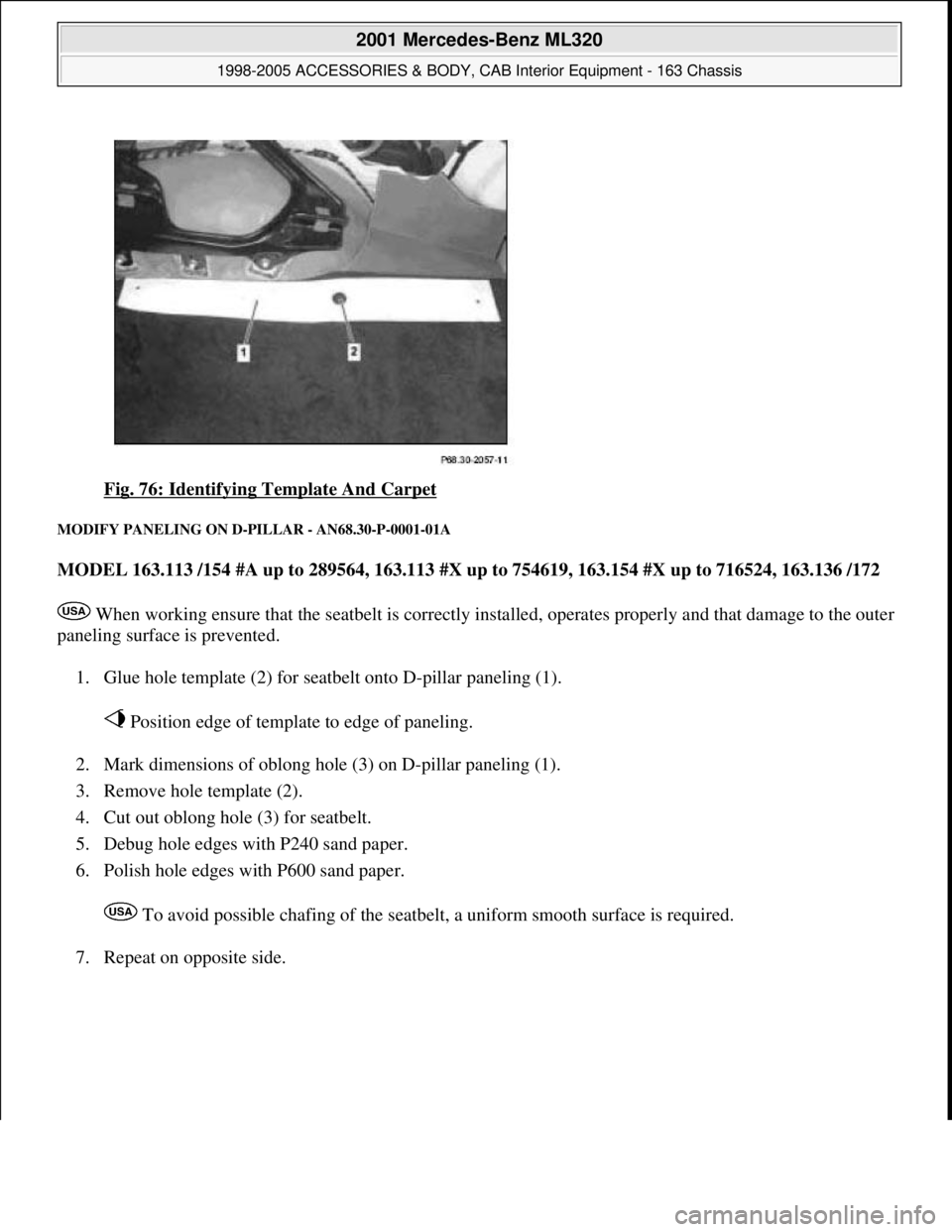
Fig. 76: Identifying Template And Carpet
MODIFY PANELING ON D-PILLAR - AN68.30-P-0001-01A
MODEL 163.113 /154 #A up to 289564, 163.113 #X up to 754619, 163.154 #X up to 716524, 163.136 /172
When working ensure that the seatbelt is correctly installed, operates properly and that damage to the outer
paneling surface is prevented.
1. Glue hole template (2) for seatbelt onto D-pillar paneling (1).
Position edge of template to edge of paneling.
2. Mark dimensions of oblong hole (3) on D-pillar paneling (1).
3. Remove hole template (2).
4. Cut out oblong hole (3) for seatbelt.
5. Debug hole edges with P240 sand paper.
6. Polish hole edges with P600 sand paper.
To avoid possible chafing of the seatbelt, a uniform smooth surface is required.
7. Repeat on opposite side.
2001 Mercedes-Benz ML320
1998-2005 ACCESSORIES & BODY, CAB Interior Equipment - 163 Chassis
me
Saturday, October 02, 2010 3:35:22 PMPage 78 © 2006 Mitchell Repair Information Company, LLC.