Page 1133 of 4133
329 Index
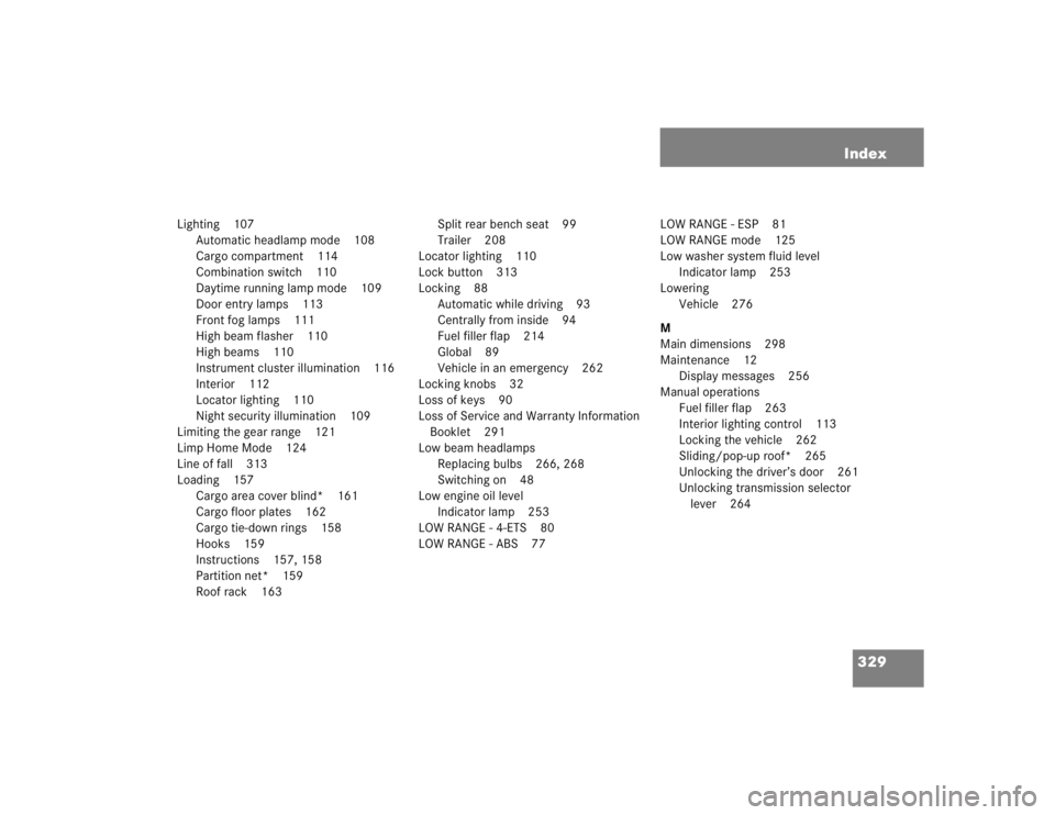
Lighting 107
Automatic headlamp mode 108
Cargo compartment 114
Combination switch 110
Daytime running lamp mode 109
Door entry lamps 113
Front fog lamps 111
High beam flasher 110
High beams 110
Instrument cluster illumination 116
Interior 112
Locator lighting 110
Night security illumination 109
Limiting the gear range 121
Limp Home Mode 124
Line of fall 313
Loading 157
Cargo area cover blind* 161
Cargo floor plates 162
Cargo tie-down rings 158
Hooks 159
Instructions 157, 158
Partition net* 159
Roof rack 163Split rear bench seat 99
Trailer 208
Locator lighting 110
Lock button 313
Locking 88
Automatic while driving 93
Centrally from inside 94
Fuel filler flap 214
Global 89
Vehicle in an emergency 262
Locking knobs 32
Loss of keys 90
Loss of Service and Warranty Information
Booklet 291
Low beam headlamps
Replacing bulbs 266, 268
Switching on 48
Low engine oil level
Indicator lamp 253
LOW RANGE - 4-ETS 80
LOW RANGE - ABS 77LOW RANGE - ESP 81
LOW RANGE mode 125
Low washer system fluid level
Indicator lamp 253
Lowering
Vehicle 276
M
Main dimensions 298
Maintenance 12
Display messages 256
Manual operations
Fuel filler flap 263
Interior lighting control 113
Locking the vehicle 262
Sliding/pop-up roof* 265
Unlocking the driver’s door 261
Unlocking transmission selector
lever 264
Page 1141 of 4133
337 Index
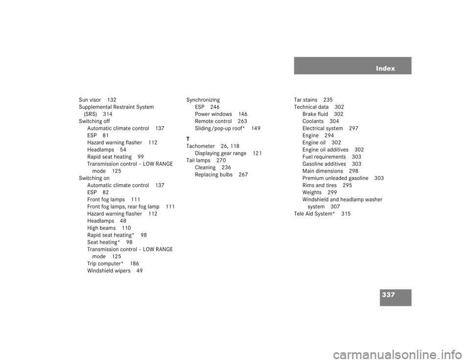
Sun visor 132
Supplemental Restraint System
(SRS) 314
Switching off
Automatic climate control 137
ESP 81
Hazard warning flasher 112
Headlamps 54
Rapid seat heating 99
Transmission control – LOW RANGE
mode 125
Switching on
Automatic climate control 137
ESP 82
Front fog lamps 111
Front fog lamps, rear fog lamp 111
Hazard warning flasher 112
Headlamps 48
High beams 110
Rapid seat heating* 98
Seat heating* 98
Transmission control – LOW RANGE
mode 125
Trip computer* 186
Windshield wipers 49Synchronizing
ESP 246
Power windows 146
Remote control 263
Sliding/pop-up roof* 149
T
Tachometer 26, 118
Displaying gear range 121
Tail lamps 270
Cleaning 236
Replacing bulbs 267Tar stains 235
Technical data 302
Brake fluid 302
Coolants 304
Electrical system 297
Engine 294
Engine oil 302
Engine oil additives 302
Fuel requirements 303
Gasoline additives 303
Main dimensions 298
Premium unleaded gasoline 303
Rims and tires 295
Weights 299
Windshield and headlamp washer
system 307
Tele Aid System* 315
Page 1961 of 4133
LARGER
CONTAINER FOR
WINDSHIELD
WASHER SYSTEM
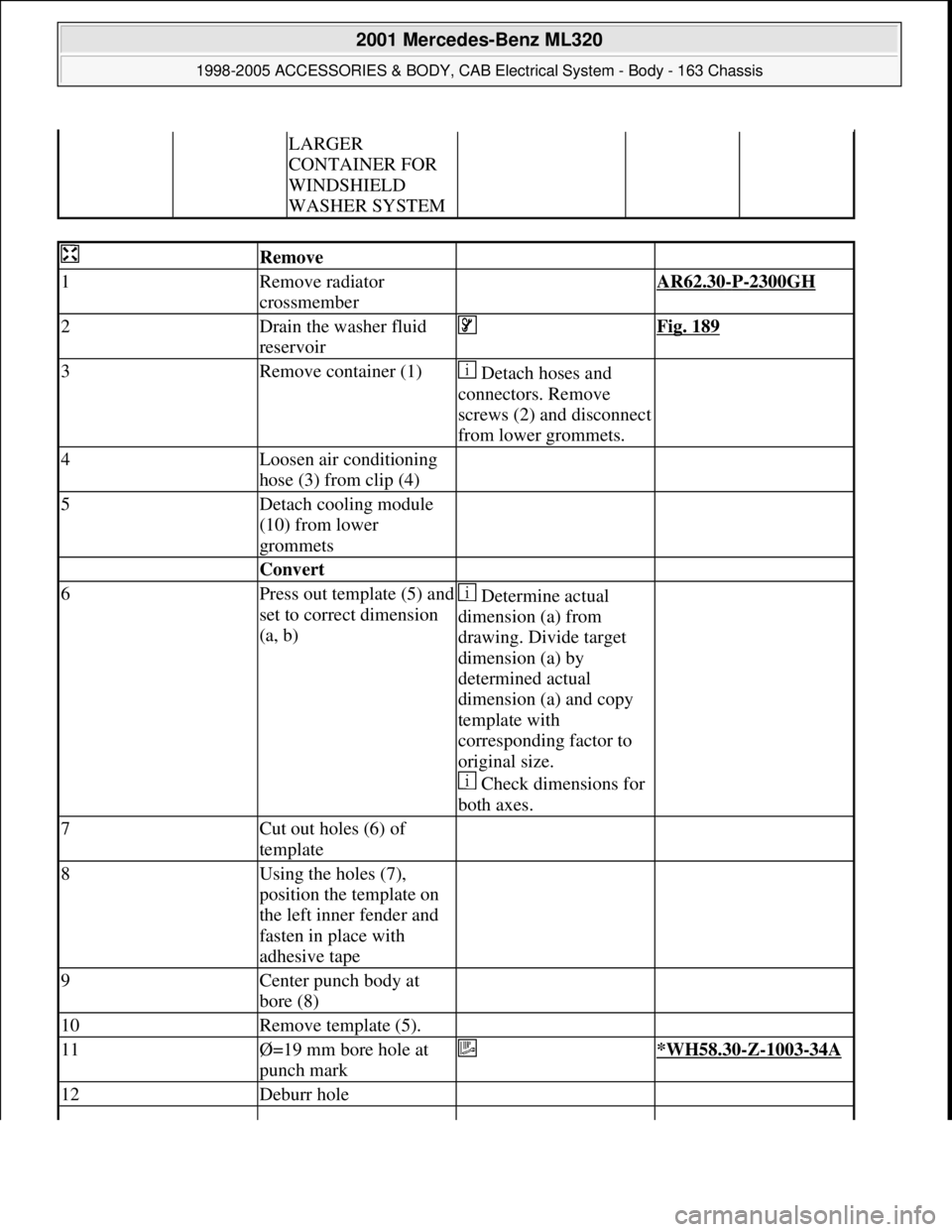
Remove
1Remove radiator
crossmember AR62.30-P-2300GH
2Drain the washer fluid
reservoir Fig. 189
3Remove container (1) Detach hoses and
connectors. Remove
screws (2) and disconnect
from lower grommets.
4Loosen air conditioning
hose (3) from clip (4)
5Detach cooling module
(10) from lower
grommets
Convert
6Press out template (5) and
set to correct dimension
(a, b) Determine actual
dimension (a) from
drawing. Divide target
dimension (a) by
determined actual
dimension (a) and copy
template with
corresponding factor to
original size.
Check dimensions for
both axes.
7Cut out holes (6) of
template
8Using the holes (7),
position the template on
the left inner fender and
fasten in place with
adhesive tape
9Center punch body at
bore (8)
10Remove template (5).
11Ø=19 mm bore hole at
punch mark *WH58.30-Z-1003-34A
12Deburr hole
2001 Mercedes-Benz ML320
1998-2005 ACCESSORIES & BODY, CAB Electrical System - Body - 163 Chassis
me
Saturday, October 02, 2010 3:30:14 PMPage 466 © 2006 Mitchell Repair Information Company, LLC.
Page 2343 of 4133
Commercially available tools
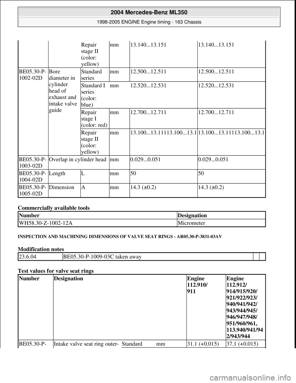
INSPECTION AND MACHINING DIMENSIONS OF VALVE SEAT RINGS - AR05.30-P-3831-03AV
Modification notes
Test values for valve seat rings
Repair
stage II
(color:
yellow)mm13.140...13.15113.140...13.151
BE05.30-P-
1002-02DBore
diameter in
cylinder
head of
exhaust and
intake valve
guideStandard
seriesmm12.500...12.51112.500...12.511
Standard I
series
(color:
blue)mm12.520...12.53112.520...12.531
Repair
stage I
(color: red)mm12.700...12.71112.700...12.711
Repair
stage II
(color:
yellow)mm13.100...13.11113.100...13.113.100...13.11113.100...13.1
BE05.30-P-
1003-02DOverlap in cylinder headmm0.029...0.0510.029...0.051
BE05.30-P-
1004-02DLengthLmm5050
BE05.30-P-
1005-02DDimensionAmm14.3 (±0.2)14.3 (±0.2)
NumberDesignation
WH58.30-Z-1002-12AMicrometer
23.6.04BE05.30-P-1009-03C taken away
NumberDesignationEngine
112.910/
911Engine
112.912/
914/915/920/
921/922/923/
940/941/942/
943/944/945/
946/947/948/
951/960/961,
113.940/941/94
2/943/944
BE05.30-P- Intake valve seat ring outer- Standardmm31.1 (+0.015)37.1 (+0.015)
2004 Mercedes-Benz ML350
1998-2005 ENGINE Engine timing - 163 Chassis
me
Saturday, October 02, 2010 3:39:39 PMPage 102 © 2006 Mitchell Repair Information Company, LLC.
Page 2348 of 4133
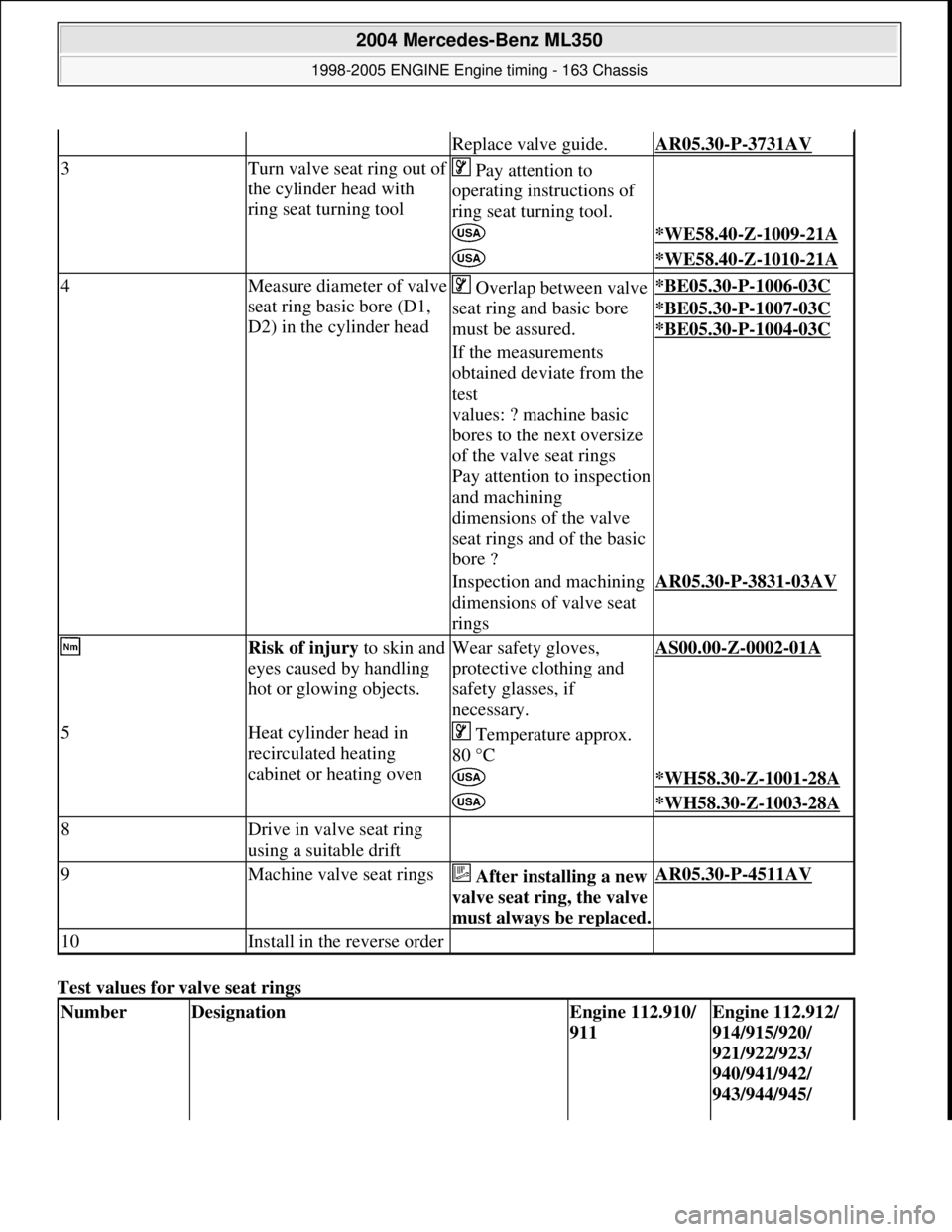
Test values for valve seat rings
Replace valve guide.AR05.30-P-3731AV
3Turn valve seat ring out of
the cylinder head with
ring seat turning tool Pay attention to
operating instructions of
ring seat turning tool.
*WE58.40-Z-1009-21A
*WE58.40-Z-1010-21A
4Measure diameter of valve
seat ring basic bore (D1,
D2) in the cylinder head Overlap between valve
seat ring and basic bore
must be assured.*BE05.30-P-1006-03C
*BE05.30-P-1007-03C
*BE05.30
-P-1004-03C
If the measurements
obtained deviate from the
test
values: ? machine basic
bores to the next oversize
of the valve seat rings
Pay attention to inspection
and machining
dimensions of the valve
seat rings and of the basic
bore ?
Inspection and machining
dimensions of valve seat
ringsAR05.30-P-3831-03AV
Risk of injury to skin and
eyes caused by handling
hot or glowing objects.Wear safety gloves,
protective clothing and
safety glasses, if
necessary.AS00.00-Z-0002-01A
5Heat cylinder head in
recirculated heating
cabinet or heating oven Temperature approx.
80 °C
*WH58.30-Z-1001-28A
*WH58.30-Z-1003-28A
8Drive in valve seat ring
using a suitable drift
9Machine valve seat rings After installing a new
valve seat ring, the valve
must always be replaced.AR05.30-P-4511AV
10Install in the reverse order
NumberDesignationEngine 112.910/
911Engine 112.912/
914/915/920/
921/922/923/
940/941/942/
943/944/945/
2004 Mercedes-Benz ML350
1998-2005 ENGINE Engine timing - 163 Chassis
me
Saturday, October 02, 2010 3:39:39 PMPage 107 © 2006 Mitchell Repair Information Company, LLC.
Page 2352 of 4133
Fig. 123: Identifying Valve Dimensions
CHECKING AND MACHINING DIMENSIONS FOR VALVE SEATS - AR05.30-P-4510-01AV
Test values for valve seat rings
965/967/968/
980/981/982/
984/987/988/
990/991/992/
993/995
BE05.30-P-
1001-01EValve disk
dia.Exhaustmm41±0,143±0,136±0,1
Intakemm36±0,138±0,133±0,1
BE05.30-P-
1002-01EValve disk
heightExhaust when
newmm1.61.61.6
Intake valve
when newmm1.21.21.1
BE05.30-P-
1003-01EValve seat
angle(aExhaust)Angle°45±15'45±15'45±15'
IntakeAngle°45±15'45±15'45±15'
BE05.30-P-
1004-01EValve stem
dia.Exhaustmm6,9706,9706,970
Intakemm6,9756,9755,975
BE05.30-P-
1005-01EValve lengthExhaustmm122,25±0,2121,80±0,2104,30 ±0,2
Intakemm119,40±0,2119,10±0,2103,60 ±0,2
NumberDesignationEngine
112.910/
911Engine 112.912/
914/915/920/
921/922/923/
940/941/942/
943/944/945/
2004 Mercedes-Benz ML350
1998-2005 ENGINE Engine timing - 163 Chassis
me
Saturday, October 02, 2010 3:39:39 PMPage 111 © 2006 Mitchell Repair Information Company, LLC.
Page 2354 of 4133
Fig. 124: Identifying Valve Seat Dimensions -Shown At Exhaust Valve Seat Ring
INSPECTING, REMOVING , INSTALLING VALVE GUIDES - AR05.30-P-4511AV
ENGINE 112
ENGINE 112.945 in MODEL 463.209 /232 /233 /244 /245 /250
ENGINE 113.962 in MODEL 463.206 /240 /241 /247 /248 /249 /254
ENGINE 113.982 in MODEL 463.243/246
ENGINE 113 in MODEL 129, 163, 202, 203, 208, 209, 210, 211, 215, 220, 230
Fig. 125: Removing/Installing Valve Guides
Remove
1Remove valves AR05.30-P-
3511AV
Inspection
2Inspect valve guide,
Inspect valve guide if the m easurements obtained are not
within the stated tolerances ?AR05.30-P-
3731-06AV
Replace valve guide.AR05.30-P-
3731AV
Machining
2004 Mercedes-Benz ML350
1998-2005 ENGINE Engine timing - 163 Chassis
me
Saturday, October 02, 2010 3:39:39 PMPage 113 © 2006 Mitchell Repair Information Company, LLC.
Page 2355 of 4133
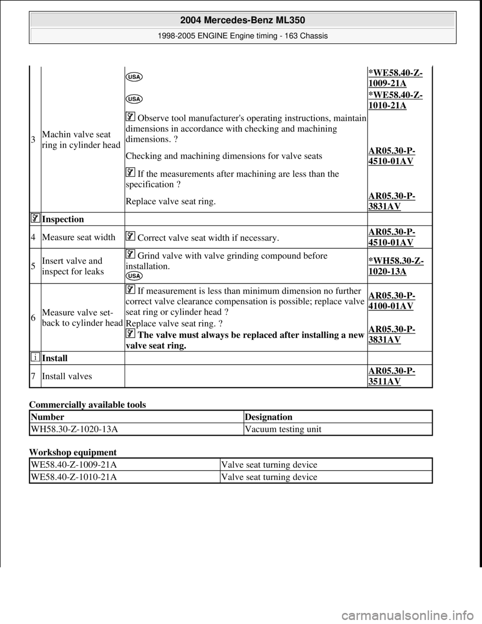
Commercially available tools
Workshop equipment
3Machin valve seat
ring in cylinder head
*WE58.40-Z-
1009-21A
*WE58.40-Z-
1010-21A
Observe tool manufacturer's operating instructions, maintain
dimensions in accordance with checking and machining
dimensions. ?
Checking and machining dime nsions for valve seatsAR05.30-P-
4510-01AV
If the measurements after machining are less than the
specification ?
Replace valve seat ring.AR05.30-P-
3831AV
Inspection
4Measure seat width Correct valve seat width if necessary.AR05.30-P-
4510-01AV
5Insert valve and
inspect for leaks Grind valve with valve grinding compound before
installation.
*WH58.30-Z-
1020-13A
6Measure valve set-
back to cylinder head
If measurement is less than minimum dimension no further
correct valve clearance compensation is possible; replace valve
seat ring or cylinder head ?AR05.30-P-
4100-01AV
Replace valve seat ring. ?
The valve must always be rep laced after installing a new
valve seat ring. AR05.30-P-
3831AV
Install
7Install valves AR05.30-P-
3511AV
NumberDesignation
WH58.30-Z-1020-13AVacuum testing unit
WE58.40-Z-1009-21AValve seat turning device
WE58.40-Z-1010-21AValve seat turning device
2004 Mercedes-Benz ML350
1998-2005 ENGINE Engine timing - 163 Chassis
me
Saturday, October 02, 2010 3:39:39 PMPage 114 © 2006 Mitchell Repair Information Company, LLC.