1997 MERCEDES-BENZ ML500 headlamp
[x] Cancel search: headlampPage 2144 of 4133
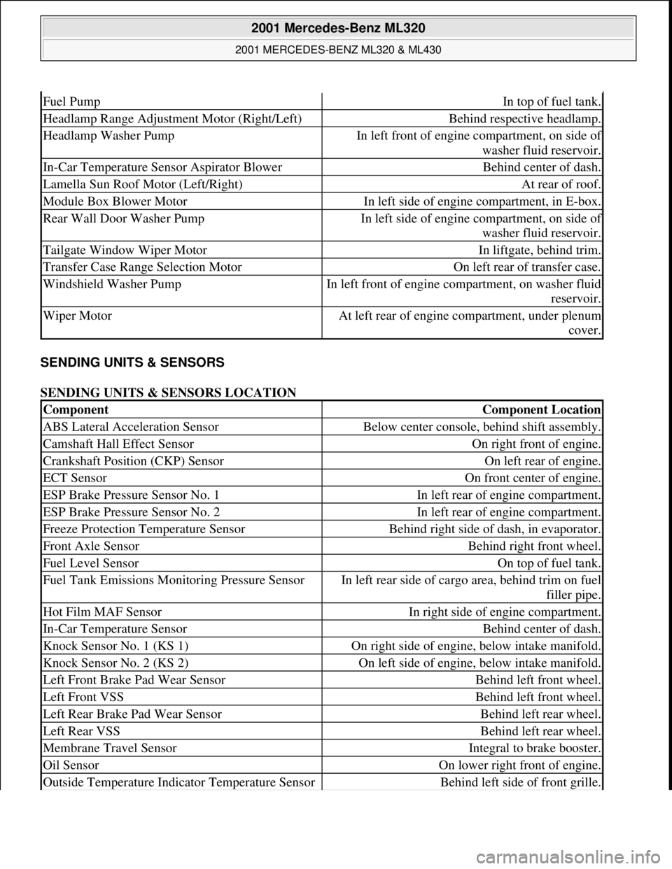
SENDING UNITS & SENSORS
SENDING UNITS & SENSORS LOCATION
Fuel PumpIn top of fuel tank.
Headlamp Range Adjustment Motor (Right/Left)Behind respective headlamp.
Headlamp Washer PumpIn left front of engine compartment, on side of
washer fluid reservoir.
In-Car Temperature Sensor Aspirator BlowerBehind center of dash.
Lamella Sun Roof Motor (Left/Right)At rear of roof.
Module Box Blower MotorIn left side of engine compartment, in E-box.
Rear Wall Door Washer PumpIn left side of engine compartment, on side of
washer fluid reservoir.
Tailgate Window Wiper MotorIn liftgate, behind trim.
Transfer Case Range Selection MotorOn left rear of transfer case.
Windshield Washer PumpIn left front of engine compartment, on washer fluid
reservoir.
Wiper MotorAt left rear of engine compartment, under plenum
cover.
ComponentComponent Location
ABS Lateral Acceleration SensorBelow center console, behind shift assembly.
Camshaft Hall Effect SensorOn right front of engine.
Crankshaft Position (CKP) SensorOn left rear of engine.
ECT SensorOn front center of engine.
ESP Brake Pressure Sensor No. 1In left rear of engine compartment.
ESP Brake Pressure Sensor No. 2In left rear of engine compartment.
Freeze Protection Temperature SensorBehind right side of dash, in evaporator.
Front Axle SensorBehind right front wheel.
Fuel Level SensorOn top of fuel tank.
Fuel Tank Emissions Monitoring Pressure SensorIn left rear side of cargo area, behind trim on fuel
filler pipe.
Hot Film MAF SensorIn right side of engine compartment.
In-Car Temperature SensorBehind center of dash.
Knock Sensor No. 1 (KS 1)On right side of engine, below intake manifold.
Knock Sensor No. 2 (KS 2)On left side of engine, below intake manifold.
Left Front Brake Pad Wear SensorBehind left front wheel.
Left Front VSSBehind left front wheel.
Left Rear Brake Pad Wear SensorBehind left rear wheel.
Left Rear VSSBehind left rear wheel.
Membrane Travel SensorIntegral to brake booster.
Oil SensorOn lower right front of engine.
Outside Temperature Indicator Temperature SensorBehind left side of front grille.
2001 Mercedes-Benz ML320
2001 MERCEDES-BENZ ML320 & ML430
me
Saturday, October 02, 2010 3:21:17 PMPage 4 © 2006 Mitchell Repair Information Company, LLC.
Page 2515 of 4133
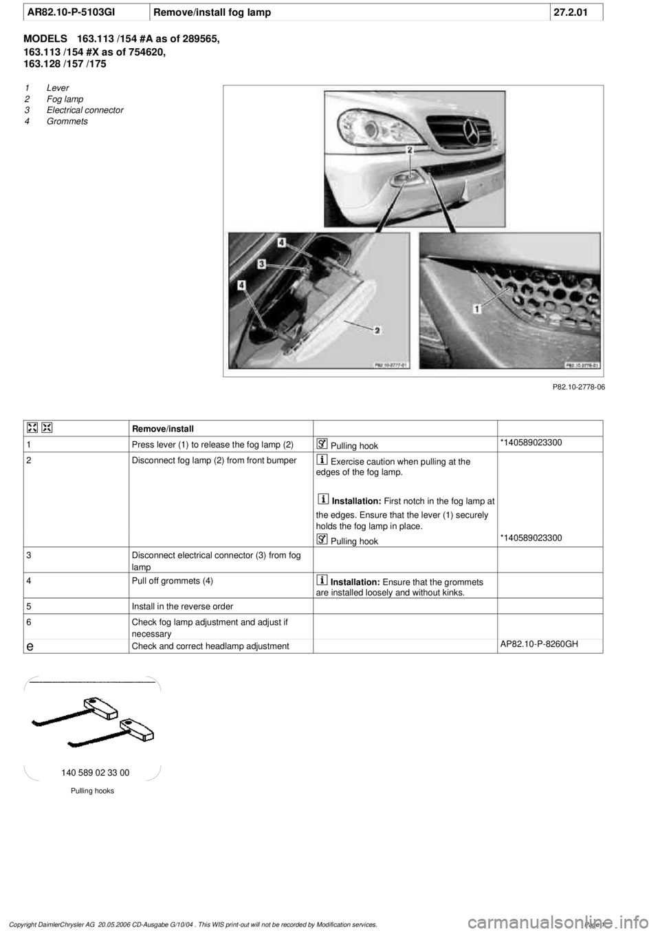
AR82.10-P-5103GI
Remove/install fog lamp
27.2.01
MODELS
163.113 /154 #A as of 289565,
163.113 /154 #X as of 754620,
163.128 /157 /175
P82.10-2778-06
1
Lever
2
Fog lamp
3
Electrical connector
4
Grommets
Remove/install
1
Press lever (1) to release the fog lamp (2)
Pulling hook
*140589023300
2
Disconnect fog lamp (2) from front bumper
Exercise caution when pulling at the
edges of the fog lamp.
Installation:
First notch in the fog lamp at
the edges. Ensure that the lever (1) securely
holds the fog lamp in place.
Pulling hook
*140589023300
3
Disconnect electrical connector (3) from fog
lamp
4
Pull off grommets (4)
Installation:
Ensure that the grommets
are installed loosely and without kinks.
5
Install in the reverse order
6
Check fog lamp adjustment and adjust if
necessary
e
Check and correct headlamp adjustment
AP82.10-P-8260GH
Pulling hooks
140 589 02 33 00
Copyright DaimlerChrysler AG 20.05.2006 CD-Ausgabe G/10/04 . This WIS print-out will not be recorde
d by Modification services.
Page 1
Page 2524 of 4133
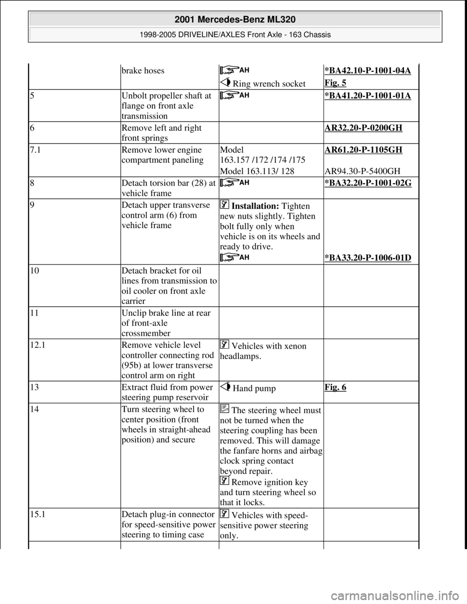
brake hoses *BA42.10-P-1001-04A
Ring wrench socketFig. 5
5Unbolt propeller shaft at
flange on front axle
transmission *BA41.20-P-1001-01A
6Remove left and right
front springs AR32.20-P-0200GH
7.1Remove lower engine
compartment panelingModel
163.157 /172 /174 /175AR61.20-P-1105GH
Model 163.113/ 128AR94.30-P-5400GH
8Detach torsion bar (28) at
vehicle frame *BA32.20-P-1001-02G
9Detach upper transverse
control arm (6) from
vehicle frame Installation: Tighten
new nuts slightly. Tighten
bolt fully only when
vehicle is on its wheels and
ready to drive.
*BA33.20-P-1006-01D
10Detach bracket for oil
lines from transmission to
oil cooler on front axle
carrier
11Unclip brake line at rear
of front-axle
crossmember
12.1Remove vehicle level
controller connecting rod
(95b) at lower transverse
control arm on right Vehicles with xenon
headlamps.
13Extract fluid from power
steering pump reservoir Hand pumpFig. 6
14Turn steering wheel to
center position (front
wheels in straight-ahead
position) and secureThe steering wheel must
not be turned when the
steering coupling has been
removed. This will damage
the fanfare horns and airbag
clock spring contact
beyond repair.
Remove ignition key
and turn steering wheel so
that it locks.
15.1Detach plug-in connector
for speed-sensitive power
steering to timing case Vehicles with speed-
sensitive power steering
only.
2001 Mercedes-Benz ML320
1998-2005 DRIVELINE/AXLES Front Axle - 163 Chassis
me
Saturday, October 02, 2010 3:38:21 PMPage 5 © 2006 Mitchell Repair Information Company, LLC.
Page 2533 of 4133
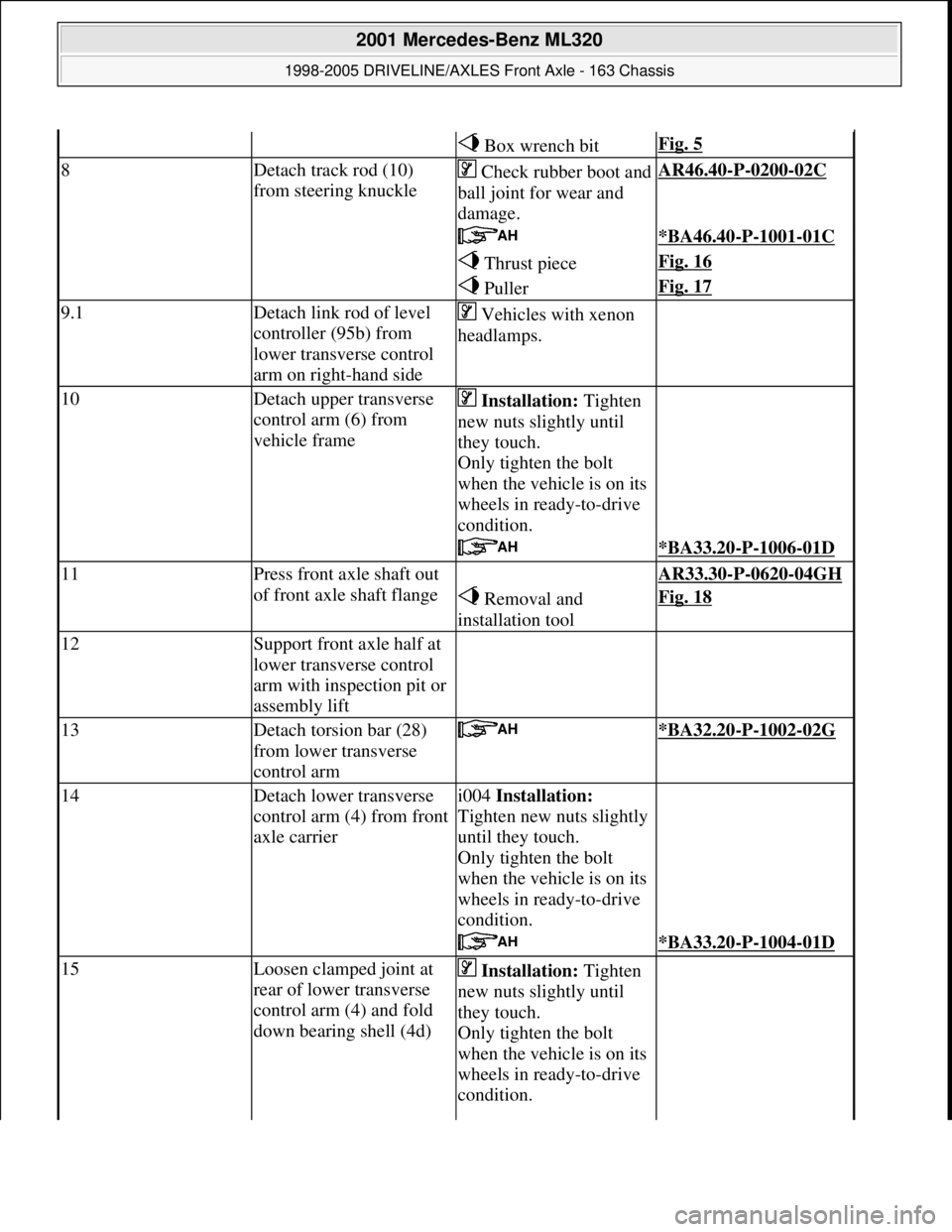
Box wrench bitFig. 5
8Detach track rod (10)
from steering knuckleCheck rubber boot and
ball joint for wear and
damage.AR46.40-P-0200-02C
*BA46.40-P-1001-01C
Thrust pieceFig. 16
PullerFig. 17
9.1Detach link rod of level
controller (95b) from
lower transverse control
arm on right-hand side Vehicles with xenon
headlamps.
10Detach upper transverse
control arm (6) from
vehicle frame Installation: Tighten
new nuts slightly until
they touch.
Only tighten the bolt
when the vehicle is on its
wheels in ready-to-drive
condition.
*BA33.20-P-1006-01D
11Press front axle shaft out
of front axle shaft flange AR33.30-P-0620-04GH
Removal and
installation toolFig. 18
12Support front axle half at
lower transverse control
arm with inspection pit or
assembly lift
13Detach torsion bar (28)
from lower transverse
control arm *BA32.20-P-1002-02G
14Detach lower transverse
control arm (4) from front
axle carrieri004 Installation:
Tighten new nuts slightly
until they touch.
Only tighten the bolt
when the vehicle is on its
wheels in ready-to-drive
condition.
*BA33.20-P-1004-01D
15Loosen clamped joint at
rear of lower transverse
control arm (4) and fold
down bearing shell (4d) Installation: Tighten
new nuts slightly until
they touch.
Only tighten the bolt
when the vehicle is on its
wheels in ready-to-drive
condition.
2001 Mercedes-Benz ML320
1998-2005 DRIVELINE/AXLES Front Axle - 163 Chassis
me
Saturday, October 02, 2010 3:38:22 PMPage 14 © 2006 Mitchell Repair Information Company, LLC.
Page 2553 of 4133
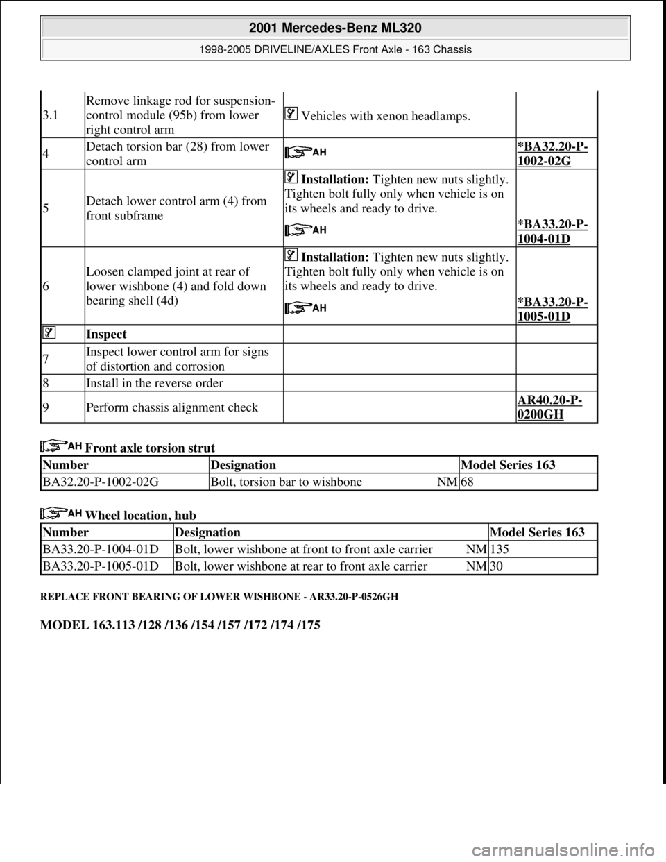
Front axle torsion strut
Wheel location, hub
REPLACE FRONT BEARING OF LOWER WISHBONE - AR33.20-P-0526GH
MODEL 163.113 /128 /136 /154 /157 /172 /174 /175
3.1
Remove linkage rod for suspension-
control module (95b) from lower
right control arm
Vehicles with xenon headlamps.
4Detach torsion bar (28) from lower
control arm *BA32.20-P-
1002-02G
5Detach lower control arm (4) from
front subframe
Installation: Tighten new nuts slightly.
Tighten bolt fully only when vehicle is on
its wheels and ready to drive.
*BA33.20-P-
1004-01D
6
Loosen clamped joint at rear of
lower wishbone (4) and fold down
bearing shell (4d)
Installation: Tighten new nuts slightly.
Tighten bolt fully only when vehicle is on
its wheels and ready to drive.
*BA33.20-P-
1005-01D
Inspect
7Inspect lower control arm for signs
of distortion and corrosion
8Install in the reverse order
9Perform chassis alignment check AR40.20-P-
0200GH
NumberDesignationModel Series 163
BA32.20-P-1002-02GBolt, torsion bar to wishboneNM68
NumberDesignationModel Series 163
BA33.20-P-1004-01DBolt, lower wishbone at front to front axle carrierNM135
BA33.20-P-1005-01DBolt, lower wishbone at rear to front axle carrierNM30
2001 Mercedes-Benz ML320
1998-2005 DRIVELINE/AXLES Front Axle - 163 Chassis
me
Saturday, October 02, 2010 3:38:22 PMPage 34 © 2006 Mitchell Repair Information Company, LLC.
Page 2610 of 4133

21
Detach rear brake cables
Unclip at underfloor of vehicle and
unscrew brake cable holder on right and left
at frame.
22.1
Unbolt check strap of rear axle carrier from
underfloor of vehicle
As of VIN A145273, X708319.
23
Remove left rear stone shield
24
Remove lower tensioning straps (80/2) and
loosen the upper tensioning straps
Tensioning straps are color-coded and
cannot be mixed up.
Support fuel tank using assembly jack.
*BA47.10-P-1001-01D
25
Remove longitudinal strut for tensioning
straps (80/18)
*BA47.10-P-1002-01D
26.1
Unscrew linkage for headlamp range
adjustment
at the top
If installed.
27
Unscrew nuts on bottom of the shock
absorbers at the transverse control arm
Installation:
Install new self-locking nuts.
*BA32.25-P-1001-03D
28
Unscrew rear axle carrier from floor of vehicle
and lower as far as possible
Support rear axle carrier.
Installation:
Install new self-locking bolts.
*BA35.10-P-1001-01C
29
Lower fuel tank
Support fuel tank.
30
Remove upper tensioning strap
at the rear
The tensioning strap at the top at the front.
31.1
Unclip lines from side of fuel tank
As of VIN A289565, X754620.
Installation:
The lines must not be
damaged.
32
Disconnect fuel pump electrical plug
connection
33
Disconnect fuel feed line (90/12) and fuel
return line (90/11)
Fuel lines must not be bent.
Pliers
*163589003700
34
Remove fuel tank (80)
Installation:
Ensure that the sealing
rubbers (5) seat correctly in the body floor to
prevent water entry.
Do not damage fuel lines at filler neck.
Guide filler neck with its chamfered side
(arrow) through between frame and body.
Filler neck and fuel tank cannot be separated
from each other.
35
Install in the reverse order
36.1
Dispose of fuel tank
Ony when replacing the fuel tank.
o
Disposal of fuel tanks
OS47.10-P-0001-01A
Rear axle carrier
Number
Designation
Model
Series 163
BA35.10-P-1001-01C
Self-locking bolt, rear axle carrier at front and rear
to frame floor
Nm
200
Propeller shaft
Number
Designation
Model
Series 163
BA41.10-P-1002-01C
Self-locking bolt, rear propsharft
at rear axle center section
Nm
50
Copyright DaimlerChrysler AG 28.05.2006 CD-Ausgabe G/10/04 . This WIS print-out will not be recorde
d by Modification services.
Page 3
Page 2650 of 4133
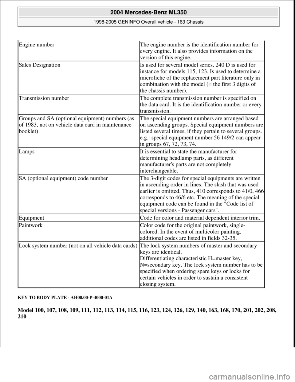
KEY TO BODY PLATE - AH00.00-P-4000-01A
Model 100, 107, 108, 109, 111, 112, 113, 114, 115, 116, 123, 124, 126, 129, 140, 163, 168, 170, 201, 202, 208,
210
Engine numberThe engine number is the identification number for
every engine. It also provides information on the
version of this engine.
Sales DesignationIs used for several model series. 240 D is used for
instance for models 115, 123. Is used to determine a
microfiche of the replacement part literature only in
combination with the model (= the first 3 digits of
the chassis number).
Transmission numberThe complete transmission number is specified on
the data card. It is the identification number or every
transmission.
Groups and SA (optional equipment) numbers (as
of 1983, not on vehicle data card in maintenance
booklet)The special equipment numbers are arranged based
on ascending groups. Special equipment numbers are
listed several times, if they pertain to several groups.
e.g.: special equipment number 56 149/2 can appear
in groups 67, 72, 73, 74.
LampsIt is essential to state the manufacturer for
determining headlamp parts, as different
manufacturer's parts are not completely
interchangeable.
SA (optional equipment) code numberThe 3-digit codes for special equipments are written
in ascending order in lines. The slash that was used
earlier is omitted. Thus, 410 corresponds to 41/0, 466
corresponds to 46/6 etc. The meaning of the special
equipment code can be found in the "Code list of
special versions - Passenger cars".
EquipmentCode for color and material dependent interior trim.
PaintworkColor code for the original paintwork, single-
colored. In the event of multicolor painting,
additional codes are listed in fields 32-35.
Lock system number (not on all vehicle data cards)The lock system numbers of master and secondary
keys are identical.
Differentiating characteristic H=master key,
N=secondary key. The lock system number has to be
specified when ordering spare keys or locks for
certain vehicles in order to sustain a consistent
closing system.
2004 Mercedes-Benz ML350
1998-2005 GENINFO Overall vehicle - 163 Chassis
me
Saturday, October 02, 2010 3:47:44 PMPage 5 © 2006 Mitchell Repair Information Company, LLC.
Page 3058 of 4133
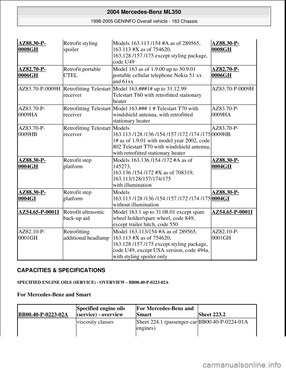
CAPACITIES & SPECIFICATIONS
SPECIFIED ENGINE OILS (SERVICE) - OVERVIEW - BB00.40-P-0223-02A
For Mercedes-Benz and Smart
AZ88.30-P-
0008GH
Retrofit styling
spoilerModels 163.113 /154 #A as of 289565,
163.113 #X as of 754620,
163.128 /157 /175 except styling package,
code U49AZ88.30-P-
0008GH
AZ82.70-P-
0006GH
Retrofit portable
CTELModel 163 as of 1.9.00 up to 30.9.01
portable cellular telephone Nokia 51 xx
and 61xxAZ82.70-P-
0006GH
AZ83.70-P-0009HRetrofitting Telestart
receiverModel 163.###1# up to 31.12.99
Telestart T60 with retrofitted stationary
heaterAZ83.70-P-0009H
AZ83.70-P-
0009HARetrofitting Telestart
receiverModel 163.### 1 # Telestart T70 with
windshield antenna, with retrofitted
stationary heaterAZ83.70-P-
0009HA
AZ83.70-P-
0009HBRetrofitting Telestart
receiverModels
163.113 /128 /136 /154 /157 /172 /174 /175
1# as of 1.9.01 with model year 2002, code
802 Telestart T70 with windshield antenna,
with retrofitted stationary heaterAZ83.70-P-
0009HB
AZ88.30-P-
0004GH
Retrofit step
platformModels 163.136 /154 /172 #A as of
145273,
163.136 /154 /172 #X as of 708319,
163.113/128/157/174/175
with illuminationAZ88.30-P-
0004GH
AZ88.30-P-
0004GI
Retrofit step
platformModels
163.113 /128 /136 /154 /157 /172 /174 /175
without illuminationAZ88.30-P-
0004GI
AZ54.65-P-0001I Retrofit ultrasonic
back-up aidModel 163.1 up to 31.08.01 except spare
wheel holder/spare wheel, code 849,
except trailer hitch, code 550AZ54.65-P-0001I
AZ82.10-P-
0001GHRetrofitting
additional headlampModel 163.113/154 #A as of 289565,
163.113 #X as of 754620,
163.128 /157 /175 except styling package,
code U49, except USA version, code 494a.
with styling spoiler onlyAZ82.10-P-
0001GH
BB00.40-P-0223-02A
Specified engine oils
(service) - overviewFor Mercedes-Benz and
Smart
Sheet 223.2
viscosity classesSheet 224.1 (passenger-car
engines)BB00.40-P-0224-01A
2004 Mercedes-Benz ML350
1998-2005 GENINFO Overall vehicle - 163 Chassis
me
Saturday, October 02, 2010 3:47:52 PMPage 413 © 2006 Mitchell Repair Information Company, LLC.