1997 MERCEDES-BENZ ML500 headlamp
[x] Cancel search: headlampPage 3186 of 4133

AP82.10-P-8260GH
Check and correct headlamp adjustment
2.7.97
MODEL
163
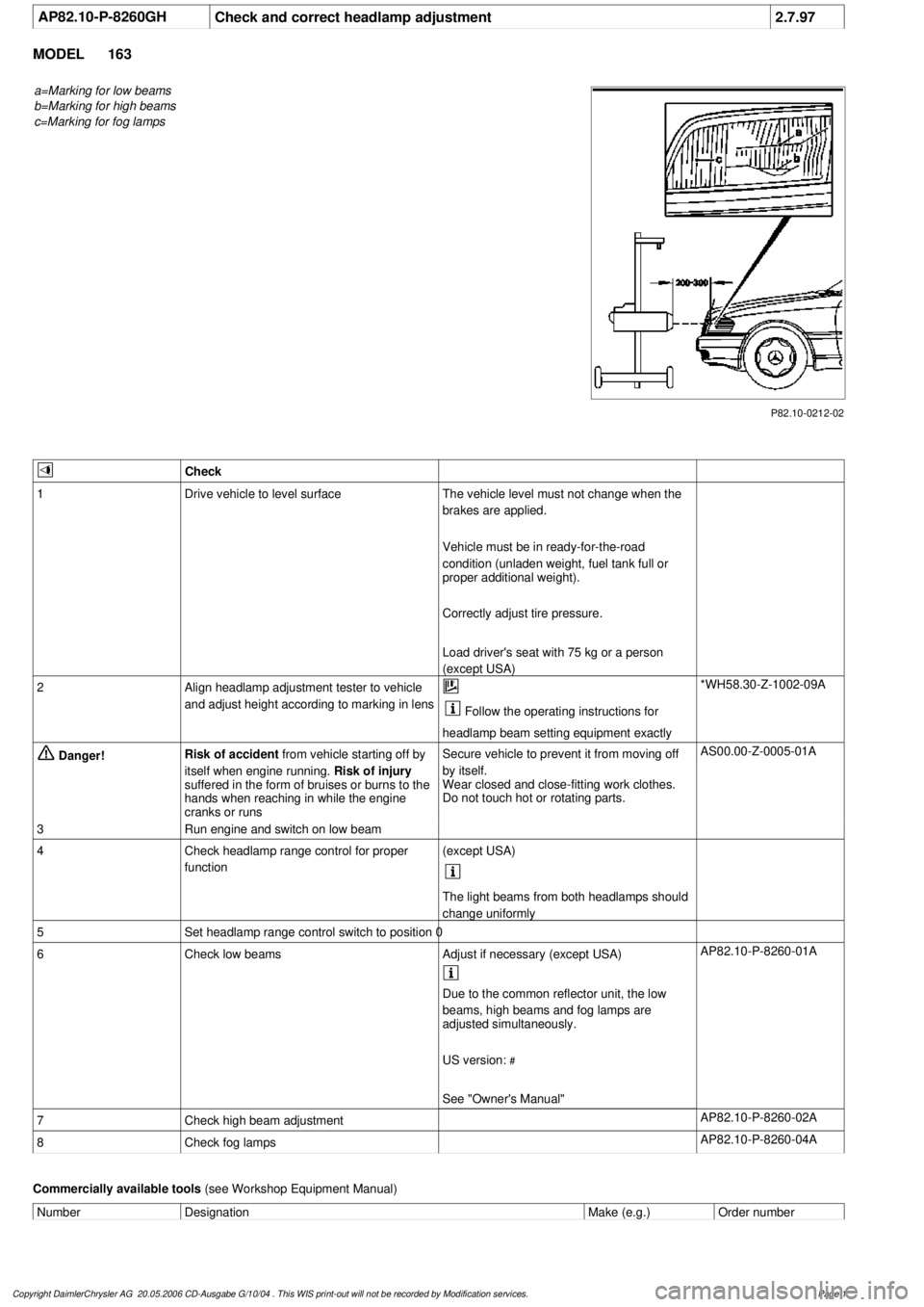
a=Marking for low beams
b=Marking for high beams
c=Marking for fog lamps
P82.10-0212-02
Check
1
Drive vehicle to level surface
The vehicle level must not change when the
brakes are applied.
Vehicle must be in ready-for-the-road
condition (unladen weight, fuel tank full or
proper additional weight).
Correctly adjust tire pressure.
Load driver's seat with 75 kg or a person
(except USA)
2
Align headlamp adjustment tester to vehicle
and adjust height according to marking in lens
Follow the operating instructions for
headlamp beam setting equipment exactly
*WH58.30-Z-1002-09A
Danger!
Risk of accident
from vehicle starting off by
itself when engine running.
Risk of injury
suffered in the form of bruises or burns to the
hands when reaching in while the engine
cranks or runs
Secure vehicle to prevent it from moving off
by itself.
Wear closed and close-fitting work clothes.
Do not touch hot or rotating parts.
AS00.00-Z-0005-01A
3
Run engine and switch on low beam
4
Check headlamp range control for proper
function
(except USA)
The light beams from both headlamps should
change uniformly
5
Set headlamp range control switch to position 0
6
Check low beams
Adjust if necessary (except USA)
AP82.10-P-8260-01A
Due to the common reflector unit, the low
beams, high beams and fog lamps are
adjusted simultaneously.
US version:
#
See "Owner's Manual"
7
Check high beam adjustment
AP82.10-P-8260-02A
8
Check fog lamps
AP82.10-P-8260-04A
Commercially available tools
(see Workshop Equipment Manual)
Number
Designation
Make (e.g.)
Order number
Copyright DaimlerChrysler AG 20.05.2006 CD-Ausgabe G/10/04 . This WIS print-out will not be recorde
d by Modification services.
Page 1
Page 3187 of 4133

WH58.30-Z-1002-09A
Headlamp adjuster
Robert Bosch GmbH
Franz Oechsle Str. 4
D-73207 Plochingen,
Germany
Copyright DaimlerChrysler AG 20.05.2006 CD-Ausgabe G/10/04 . This WIS print-out will not be recorde
d by Modification services.
Page 2
Page 3194 of 4133

15
Adjust gap dimensions
Gap dimensions
*BE60.00-P-1001-01D
Feeler gage
*129589032100
16
Align engine hood catch upper section (5)
centered in longitudinal and transverse
direction to engine hood catch lower section
and tighten
*BA88.40-P-1004-01C
17
Ensure that engine hood catch catches
properly
For this purpose, close engine hood and
pull upward with a jerk.
18
Release engine hood and ensure that safety
hook catches on radiator crossmember
19
Close engine hood (2)
Test and adjustment values, gap dimensions at hoods, doors and covers
Number
Designation
Model 163
BE60.00-P-1001-01D
Gap
dimension
Engine hood to fender
Dimension "A"
mm
5.0 (
F
0.5)
Engine hood to headlamp
Dimension "R"
mm
5.0 (
F
0.5)
Engine hood to radiator grille
Dimension "O"
mm
5.0 (
F
0.5)
Radiator grill to headlamp
Dimension "N"
mm
-
Fig., see
AR60.00-P-0700-
01GH
Engine hood
Number
Designation
Model 163
BA88.40-P-1001-01C
Bolt, engine hood hinge on engine hood
Nm
10
BA88.40-P-1002-01C
Nut, engine hood hinge to body
Nm
18
BA88.40-P-1004-01C
Bolt, engine hood catch upper section to engine
hood
Nm
12
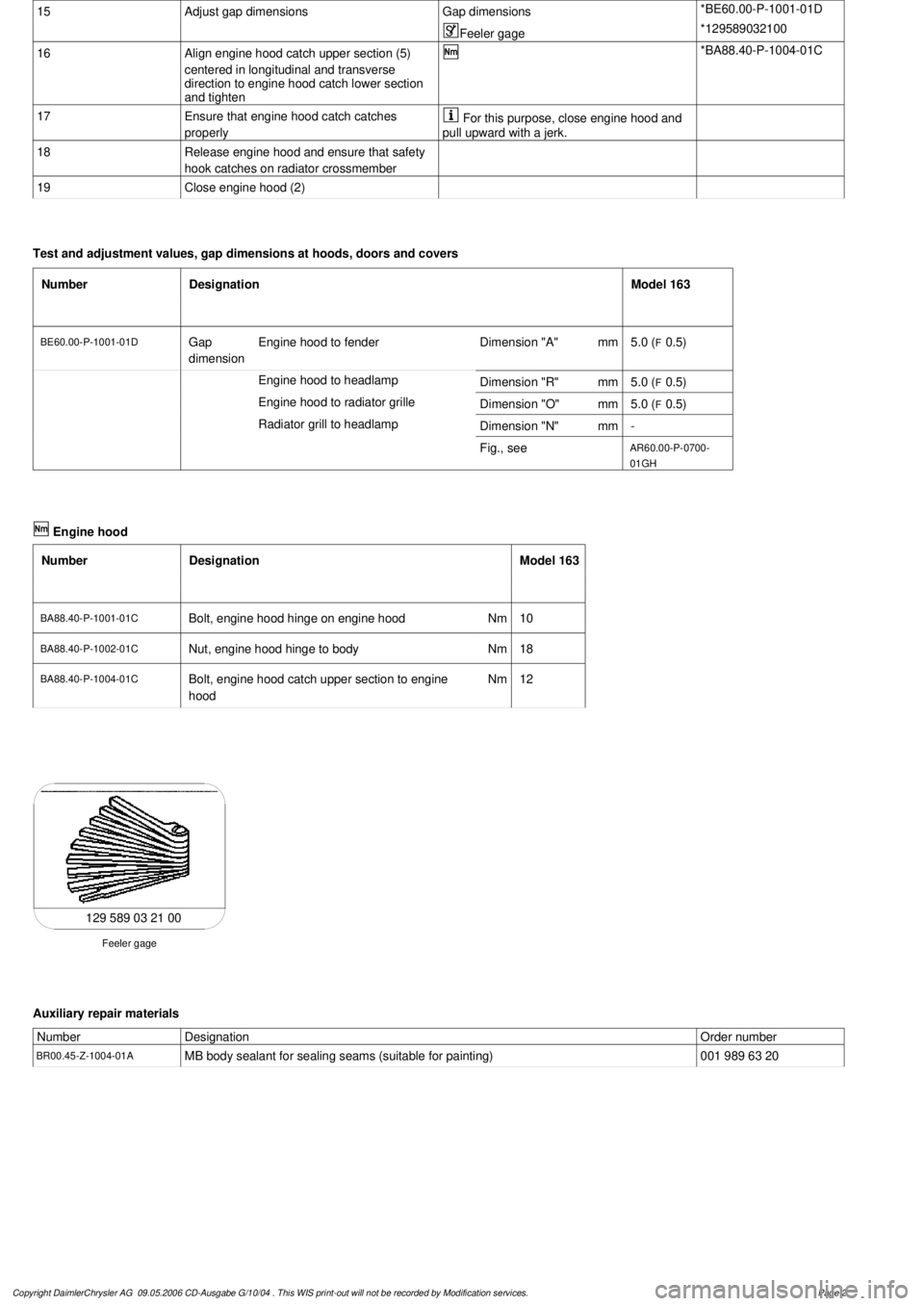
129 589 03 21 00
Feeler gage
Auxiliary repair materials
Number
Designation
Order number
BR00.45-Z-1004-01A
MB body sealant for sealing seams (suitable for painting)
001 989 63 20
Copyright DaimlerChrysler AG 09.05.2006 CD-Ausgabe G/10/04 . This WIS print-out will not be recorde
d by Modification services.
Page 2
Page 3196 of 4133

15
Adjust gap dimensions
Gap dimensions
*BE60.00-P-1001-01D
Feeler gage
*129589032100
16
Align engine hood catch upper section (5)
centered in longitudinal and transverse
direction to engine hood catch lower section
and tighten
*BA88.40-P-1004-01C
17
Ensure that engine hood catch catches
properly
For this purpose, close engine hood and
pull upward with a jerk.
18
Release engine hood and ensure that safety
hook catches on radiator crossmember
19
Close engine hood (2)
Test and adjustment values, gap dimensions at hoods, doors and covers
Number
Designation
Model 163
BE60.00-P-1001-01D
Gap
dimension
Engine hood to fender
Dimension "A"
mm
5.0 (
F
0.5)
Engine hood to headlamp
Dimension "R"
mm
5.0 (
F
0.5)
Engine hood to radiator grille
Dimension "O"
mm
5.0 (
F
0.5)
Radiator grill to headlamp
Dimension "N"
mm
-
Fig., see
AR60.00-P-0700-
01GH
Engine hood
Number
Designation
Model 163
BA88.40-P-1001-01C
Bolt, engine hood hinge on engine hood
Nm
10
BA88.40-P-1002-01C
Nut, engine hood hinge to body
Nm
18
BA88.40-P-1004-01C
Bolt, engine hood catch upper section to engine
hood
Nm
12
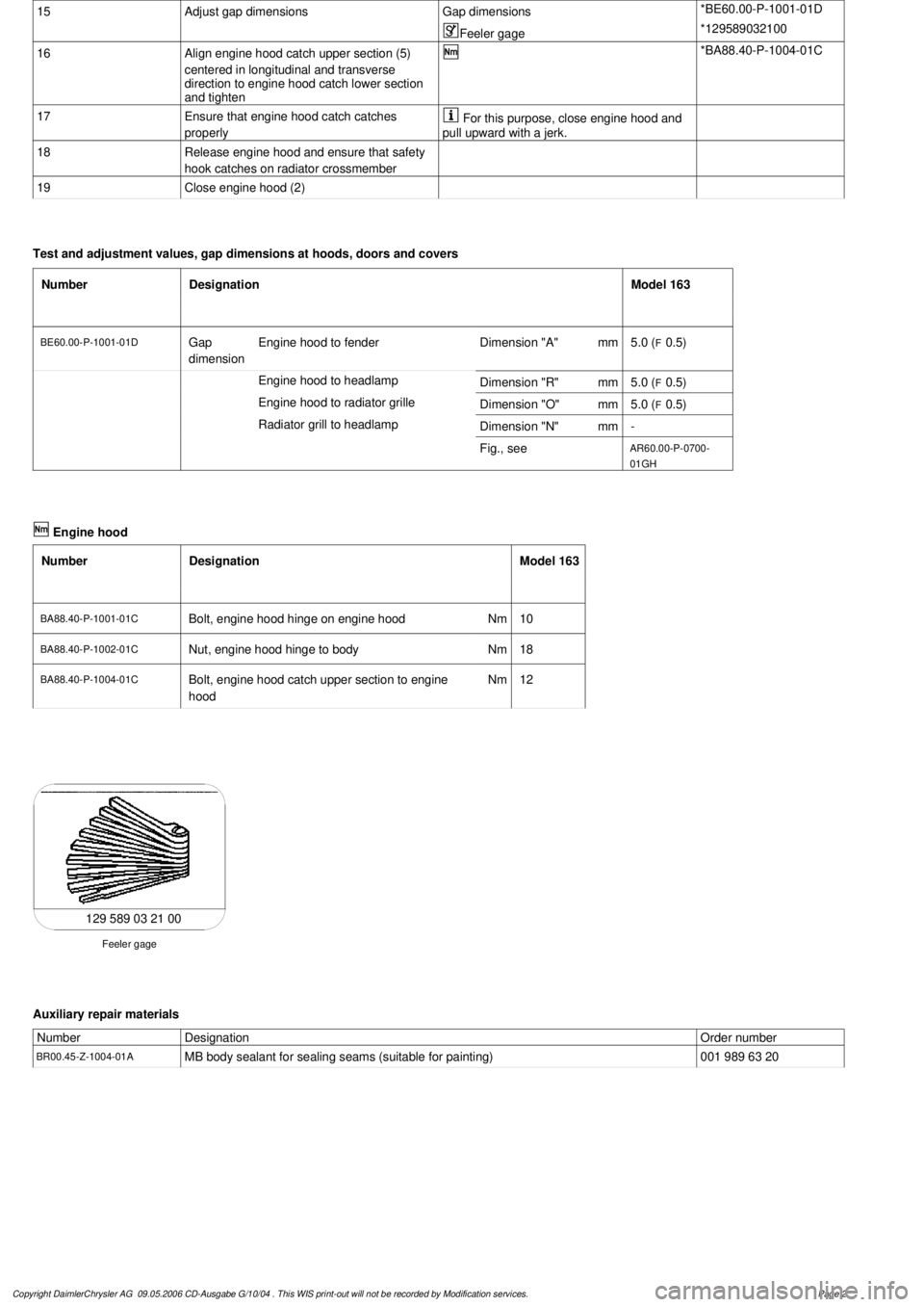
129 589 03 21 00
Feeler gage
Auxiliary repair materials
Number
Designation
Order number
BR00.45-Z-1004-01A
MB body sealant for sealing seams (suitable for painting)
001 989 63 20
Copyright DaimlerChrysler AG 09.05.2006 CD-Ausgabe G/10/04 . This WIS print-out will not be recorde
d by Modification services.
Page 2
Page 3504 of 4133

7.1
Disconnect electrical connectors at the covers
12)
Only with left/right folding outside mirror,
code 500 and headlamp cleaning system,
code 600.
8
Unscrew screw (4) and disconnect connector
(9)
9
Unscrew screw (8) and remove cruise control
switch (S40)
10
Unscrew screws (5)
11
Pull combination switch (S4) off the retaining
webs (6) and remove
12
Install in the reverse order
13
Perform function check
Copyright DaimlerChrysler AG 09.05.2006 CD-Ausgabe G/10/04 . This WIS print-out will not be recorde
d by Modification services.
Page 2
Page 3756 of 4133

AR20.20-P-3865HC
Remove/install the radiator
5.6.97
ENGINE
112.942 in MODEL 163.154
ENGINE
112.970 in MODEL 163.157
ENGINE
113.942 in MODEL 163.172
ENGINE
113.965 in MODEL 163.175
ENGINE
113.981 in MODEL 163.174
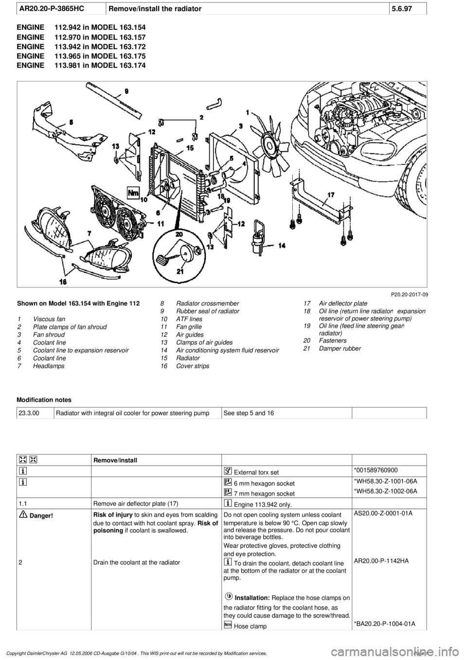
P20.20-2017-09
Shown on Model 163.154 with Engine 112
1
Viscous fan
2
Plate clamps of fan shroud
3
Fan shroud
4
Coolant line
5
Coolant line to expansion reservoir
6
Coolant line
7
Headlamps
17
Air deflector plate
18
Oil line (return line radiator
!
expansion
reservoir of power steering pump)
19
Oil line (feed line steering gear
!
radiator)
20
Fasteners
21
Damper rubber
8
Radiator crossmember
9
Rubber seal of radiator
10
ATF lines
11
Fan grille
12
Air guides
13
Clamps of air guides
14
Air conditioning system fluid reservoir
15
Radiator
16
Cover strips
Modification notes
23.3.00
Radiator with integral oil cooler for power steering pump
See step 5 and 16
Remove/install
External torx set
*001589760900
6 mm hexagon socket
*WH58.30-Z-1001-06A
7 mm hexagon socket
*WH58.30-Z-1002-06A
1.1
Remove air deflector plate (17)
Engine 113.942 only.
Danger!
Risk of injury
to skin and eyes from scalding
due to contact with hot coolant spray.
Risk of
poisoning
if coolant is swallowed.
Do not open cooling system unless coolant
temperature is below 90 °C. Open cap slowly
and release the pressure. Do not pour coolant
into beverage bottles.
Wear protective gloves, protective clothing
and eye protection.
AS20.00-Z-0001-01A
2
Drain the coolant at the radiator
To drain the coolant, detach coolant line
at the bottom of the radiator or at the coolant
pump.
Installation:
Replace the hose clamps on
the radiator fitting for the coolant hose, as
they could cause damage to the screw/thread. AR20.00-P-1142HA
Hose clamp
*BA20.20-P-1004-01A
Copyright DaimlerChrysler AG 12.05.2006 CD-Ausgabe G/10/04 . This WIS print-out will not be recorde
d by Modification services.
Page 1
Page 3757 of 4133

3.1
Remove viscous fan (1)
Engine 112.942 /970 and 113.942.
Right-hand thread!
AR20.40-P-5660C
3.2
Remove electric fan
Only Engine 113.965 /981.
AR20.40-P-5000GH
4.1
Pull off plate clamps of fan shroud (2)
Only for Engine 112.942, from 5/98.
5.1
Remove fan shroud (3)
Only for Engine 112.942 /970 und
113.942. Unscrew the bolts at bottom of fan
shroud for this step
Installation:
If installing a new radiator
with integral power steering pump oil cooler, a
new fan shroud is required if a radiator
without integral oil cooler was previously
installed.
6
Remove headlamp (7).
AR82.10-P-4730GH
7
Remove radiator crossmember (8)
AR62.30-P-2300GH
8
Detach coolant line (4, 6) and expansion
reservoir coolant line (5) at the radiator
Installation:
Replace the hose clamps on
the radiator fitting for the coolant hose, as
they could cause damage to the screw/thread.
Hose clamp
*BA20.20-P-1004-01A
9
Remove the rubber seal on radiator (9)
10.1
Remove oil line (return line of radiator
!
power steering pump expansion reservoir)
(18) and oil line (feed line of steering gear
!
radiator) (19)
From 5/98 only, seal off the connections.
Set of plugs
*129589009100
11
Unscrew ATF lines (10) at the radiator
Seal off the connections.
*BA20.20-P-1001-01A
*BA20.20-P-1003-01A
Set of plugs
*129589009100
12.1
Detach the connector from the fan and
remove the fan grille (11)
Only for Engine 112.942 /970 and 113.942.
13
Unscrew the condenser from the radiator
Do not disconnect the lines.
14
Remove fasteners (20) and damper rubber
(21)
The damper rubber (21) is designed to
prevent possible vibrations between the
condenser and radiator (15) during off-road
driving.
15
Remove air conditioning system fluid
reservoir (14) from the radiator
Place aside with the lines connected.
Detach the condenser from the radiator.
16
Remove radiator (15)
When installing, the spigots on the
radiator must be inserted in the rubber
grommets in the bottom crossmember.
Installation:
On Model 163.154 with
Engine 112.942 before VIN end number
043553, when installing a new radiator with
integral power steering pump oil cooler,
additional operations are required, if they
have not already been carried out:
#
v
Retrofit the bracket for the oil cooler line of
the power steering pump
SM46.30-P-0002A
k
Radiator with integral oil cooler for the power
steering pump
BT20.20-P-0001-01A
17
Detach air guides (12)
Replace the clamps on air guides (13).
18
Install in the reverse order
19
Pour in coolant
AR20.00-P-1142HA
20
Check the headlamp setting and correct if
necessary
e
Check and adjust the headlamp setting
AP82.10-P-8260GH
Danger!
Risk of accident
caused by vehicle starting
off when engine is running.
Risk of injury
caused by contusions and burns when
working in engine during starting procedure
Secure the vehicle to prevent it from moving.
Wear closed and snug-fitting work clothes.
Do not grasp hot or rotating parts.
AS00.00-Z-0005-01A
21
Check the oil level in the automatic
transmission and correct if necessary
AR27.00-P-0101A
22
Check the cooling system for leaks
AR20.00-P-1010HA
Radiator, coolant hoses
Copyright DaimlerChrysler AG 12.05.2006 CD-Ausgabe G/10/04 . This WIS print-out will not be recorde
d by Modification services.
Page 2
Page 3762 of 4133

13
Disconnect coolant hose to coolant pump (8),
coolant hose from thermostat housing (9) and
coolant hose from coolant expansion tank
(10) at radiator
Hexagon socket wrench
*WH58.30-Z-1001-06A
Hexagon socket wrench
*WH58.30-Z-1002-06A
14
Detach air guides (12)
Installation:
Replace fastening clamps
(13)
15
Unscrew bolts (16) at condenser (17) to
radiator
Avoid deformation of condenser lines.
Do not disconnect lines.
16
Remove attachment parts (20) and rubber
shock absorber (21)
Installation:
Ensure, that the rubber
shock absorbers do not drop when installing
the radiator.
Replace fastening clamps.
17
Take off fluid reservoir of AC (14) at radiator
Place to the side with lines connected.
External torx set
*001589760900
18
Remove bracket of charge air pipe at left
radiator
Installation:
Insert bracket of charge air
pipe into the bracket at the radiator.
19
Remove radiator (15)
Installation:
When installing, the mounting
studs of the radiator must be inserted into the
rubber grommets of the lower crossmember.
20
Install in the reverse order
21
Check headlamp adjustment, correct if
necessary
e
Check and correct headlamp adjustment
AP82.10-P-8260A
22
Inspect cooling system for leaks
AR20.00-P-1010HA
23
Fill power steering pump and bleed
Danger!
Risk of accident
caused by vehicle starting
off by itself when engine is running.
Risk of
injury
caused by contusions and burns when
working in engine during starting procedure
Secure vehicle to prevent it from moving.
Wear closed and snug-fitting work clothes.
Do not grasp hot or rotating parts.
AS00.00-Z-0005-01A
24
Run engine and inspect for leaks
Crankcase ventilation, cylinder head cover
Number
Designation
Engine
612.963
BA01.20-P-1002-01A
Bolt, cylinder head cover trim panel to
cylinder head cover
Nm
10
BA01.20-P-1003-01A
Bolt, cover panel to charge air distribution
pipe
Nm
10
Power steering pump
Number
Designation
Model
163.113
BA46.30-P-1012-01A
Banjo bolt, power steering oil line to radiator
Nm
30
Cooling system
Number
Designation
Engine
612.963
BF20.00-P-1001-02E
Cooling system
Total capacity
Liter
Y
11.0
Copyright DaimlerChrysler AG 12.05.2006 CD-Ausgabe G/10/04 . This WIS print-out will not be recorde
d by Modification services.
Page 3