1997 MERCEDES-BENZ ML430 traction control
[x] Cancel search: traction controlPage 1449 of 4133
The ETC control module (N15/3) determines the instantaneous operating condition of the vehicle and controls
all gearshift sequences taking into account the ease of shifting and the driving situation. See Fig. 158
. This
involves receiving , converting and transmitting various digital and analog signals.
Input Signals:
Starter Lock-Out Contact (Y3/6S1)
RPM Sensor 2 (Y3/6N2)
RPM Sensor 3 (Y3/6N3)
Transmission Oil Temperature Sensor (Y3/6B1)
Kickdown Switch (S16/6)
Gear Recognition Switch (S16/10)
Output signals:
Reverse/Parking Lock Valve
Input And Output Signals:
Datalink Connector (X11/4)
In addition there is a connection via the engine compartment bus to the:
ME-SFI Control Module (N3/10) or CDI Control Module (N3/9)
Traction System Control Module (N47)
Transfer Case Control Module (N78)
The solenoid valves for the modulating and shift pressure and for the gear changes are actuated by the ETC
control module (N15/3). The pressure required is calculated from all input signals, adjusted to the torque to be
transferred.
The following information from other systems is then processed:
ME-SFI Control Module (N3/10) or CDI Control Module (N3/9)
Reverse And Parking Lock Solenoids (Y66/1)
Selector Lever Position (P/N) to the Engine Control Module (ME-SFI) (N3/10) (only on detection of the
selector lever position "P" or "N" on the transmission range recognition switch (S16/10) and at the starter
interlock contact (Y3/6s1)).
Traction System Control Module (N47):
Wheel Speeds
Gear Shift
Traction Status
2001 Mercedes-Benz ML320
1998-03 AUTOMATIC TRANSMISSIONS Complete Transmissions - ML 320 - 722.662
me
Saturday, October 02, 2010 3:15:29 PMPage 280 © 2006 Mitchell Repair Information Company, LLC.
Page 1450 of 4133
Transfer Case Control Module (N78):
Position of Transfer Case (off-road or on-road ratio)
Engine Torque
Engine Speed
Accelerator Pedal Position
Gear Soft
Engine Status
The following information is output to other systems:
ME-SFI Control Module (N3/10) or CDI Control Module (N3/9):
Kickdown Switch (S16/6)
Engage Drive Mode
Traction System Control Module (N47):
Transmission Ratio
Speeds
Oil Level Control, Function
Operation - The oil level control system seals the opening between the oil gallery and gearset chamber so that
the rotating gearsets do not splash about in oil as the oil level rises. The oil level control reduces power loss and
prevents oil from being thrown out of the transmission housing at high oil temperatures.
Float, Location/Function
See SHIFT PRESSURE REGULATING VALVE, LOCATION/TASK/FUNCTION
.
Transmission Housing Breathing, Location/Task
See TRANSMISSION HOUSING BREATHING, LOCATION/TASK
.
Function Of Torque Converter Lockup Clutch Control
Operation
2001 Mercedes-Benz ML320
1998-03 AUTOMATIC TRANSMISSIONS Complete Transmissions - ML 320 - 722.662
me
Saturday, October 02, 2010 3:15:29 PMPage 281 © 2006 Mitchell Repair Information Company, LLC.
Page 1576 of 4133
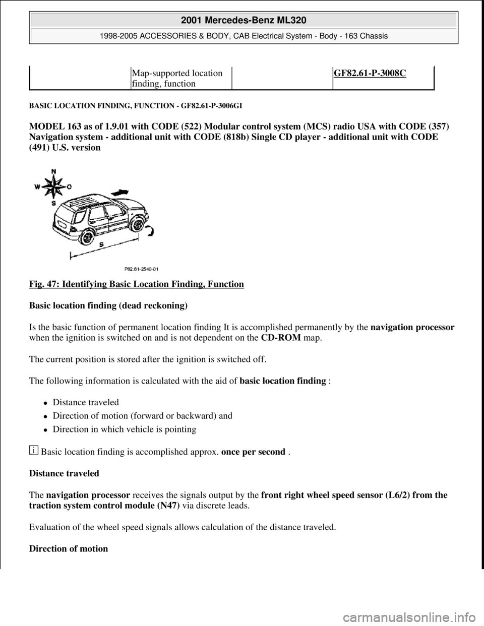
BASIC LOCATION FINDING, FUNCTION - GF82.61-P-3006GI
MODEL 163 as of 1.9.01 with CODE (522) Modular control system (MCS) radio USA with CODE (357)
Navigation system - additional unit with CODE (818b) Single CD player - additional unit with CODE
(491) U.S. version
Fig. 47: Identifying Basic Location Finding, Function
Basic location finding (dead reckoning)
Is the basic function of permanent location finding It is accomplished permanently by the navigation processor
when the ignition is switched on and is not dependent on the CD-ROM map.
The current position is stored after the ignition is switched off.
The following information is calculated with the aid of basic location finding :
Distance traveled
Direction of motion (forward or backward) and
Direction in which vehicle is pointing
Basic location finding is accomplished approx. once per second .
Distance traveled
The navigation processor receives the signals output by the front right wheel speed sensor (L6/2) from the
traction system control module (N47) via discrete leads.
Evaluation of the wheel speed signals allows calculation of the distance traveled.
Direction of motion
Map-supported location
finding, function GF82.61-P-3008C
2001 Mercedes-Benz ML320
1998-2005 ACCESSORIES & BODY, CAB Electrical System - Body - 163 Chassis
me
Saturday, October 02, 2010 3:30:05 PMPage 81 © 2006 Mitchell Repair Information Company, LLC.
Page 1770 of 4133
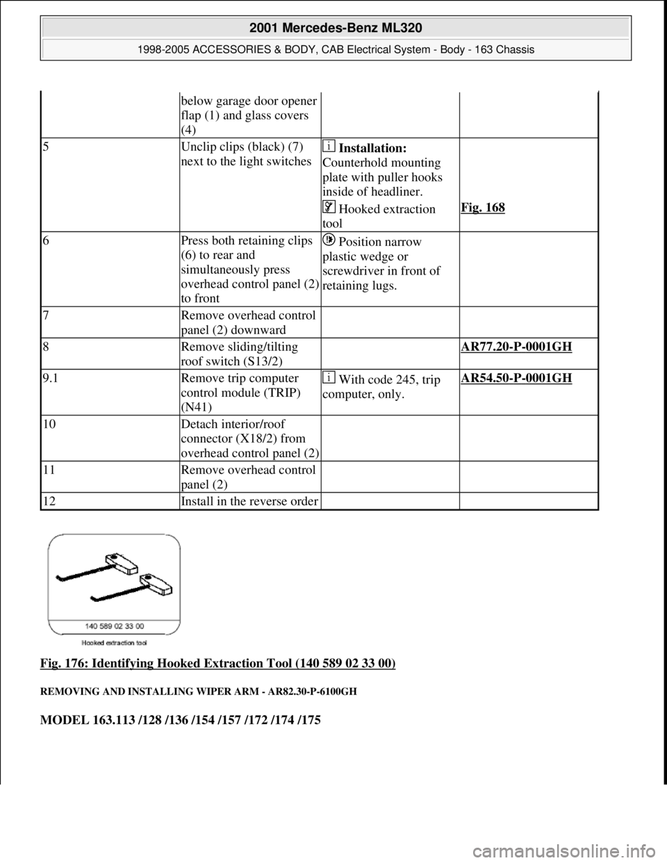
Fig. 176: Identifying Hooked Extraction Tool (140 589 02 33 00)
REMOVING AND INSTALLING WIPER ARM - AR82.30-P-6100GH
MODEL 163.113 /128 /136 /154 /157 /172 /174 /175
below garage door opener
flap (1) and glass covers
(4)
5Unclip clips (black) (7)
next to the light switches Installation:
Counterhold mounting
plate with puller hooks
inside of headliner.
Hooked extraction
toolFig. 168
6Press both retaining clips
(6) to rear and
simultaneously press
overhead control panel (2)
to front Position narrow
plastic wedge or
screwdriver in front of
retaining lugs.
7Remove overhead control
panel (2) downward
8Remove sliding/tilting
roof switch (S13/2) AR77.20-P-0001GH
9.1Remove trip computer
control module (TRIP)
(N41) With code 245, trip
computer, only.AR54.50-P-0001GH
10Detach interior/roof
connector (X18/2) from
overhead control panel (2)
11Remove overhead control
panel (2)
12Install in the reverse order
2001 Mercedes-Benz ML320
1998-2005 ACCESSORIES & BODY, CAB Electrical System - Body - 163 Chassis
me
Saturday, October 02, 2010 3:30:09 PMPage 275 © 2006 Mitchell Repair Information Company, LLC.
Page 2554 of 4133
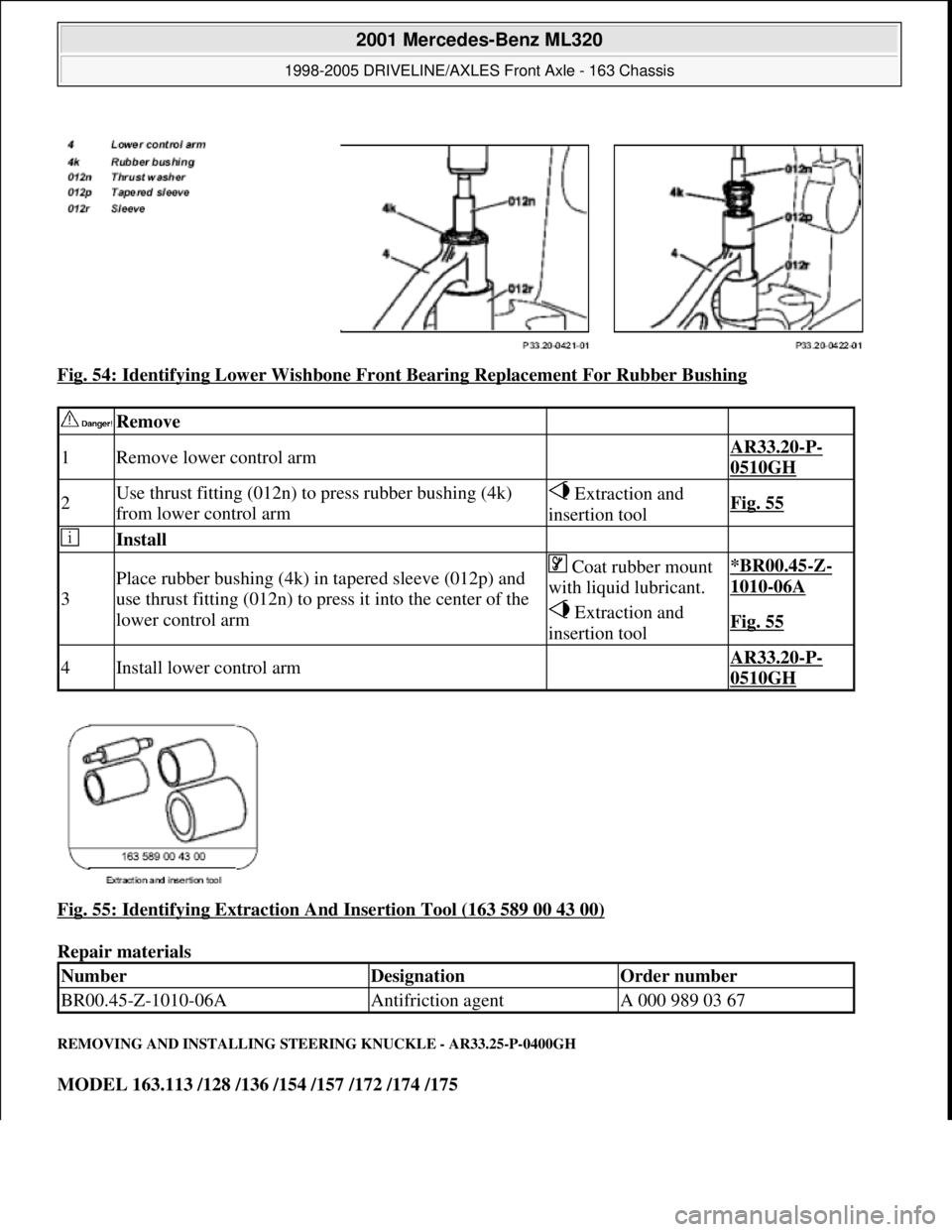
Fig. 54: Identifying Lower Wishbone Front Bearing Replacement For Rubber Bushing
Fig. 55: Identifying Extraction And Insertion Tool (163 589 00 43 00)
Repair materials
REMOVING AND INSTALLING STEERING KNUCKLE - AR33.25-P-0400GH
MODEL 163.113 /128 /136 /154 /157 /172 /174 /175
Remove
1Remove lower control arm AR33.20-P-
0510GH
2Use thrust fitting (012n) to press rubber bushing (4k)
from lower control arm Extraction and
insertion toolFig. 55
Install
3
Place rubber bushing (4k) in tapered sleeve (012p) and
use thrust fitting (012n) to press it into the center of the
lower control arm Coat rubber mount
with liquid lubricant.*BR00.45-Z-
1010-06A
Extraction and
insertion toolFig. 55
4Install lower control arm AR33.20-P-
0510GH
NumberDesignationOrder number
BR00.45-Z-1010-06AAntifriction agentA 000 989 03 67
2001 Mercedes-Benz ML320
1998-2005 DRIVELINE/AXLES Front Axle - 163 Chassis
me
Saturday, October 02, 2010 3:38:22 PMPage 35 © 2006 Mitchell Repair Information Company, LLC.
Page 2556 of 4133
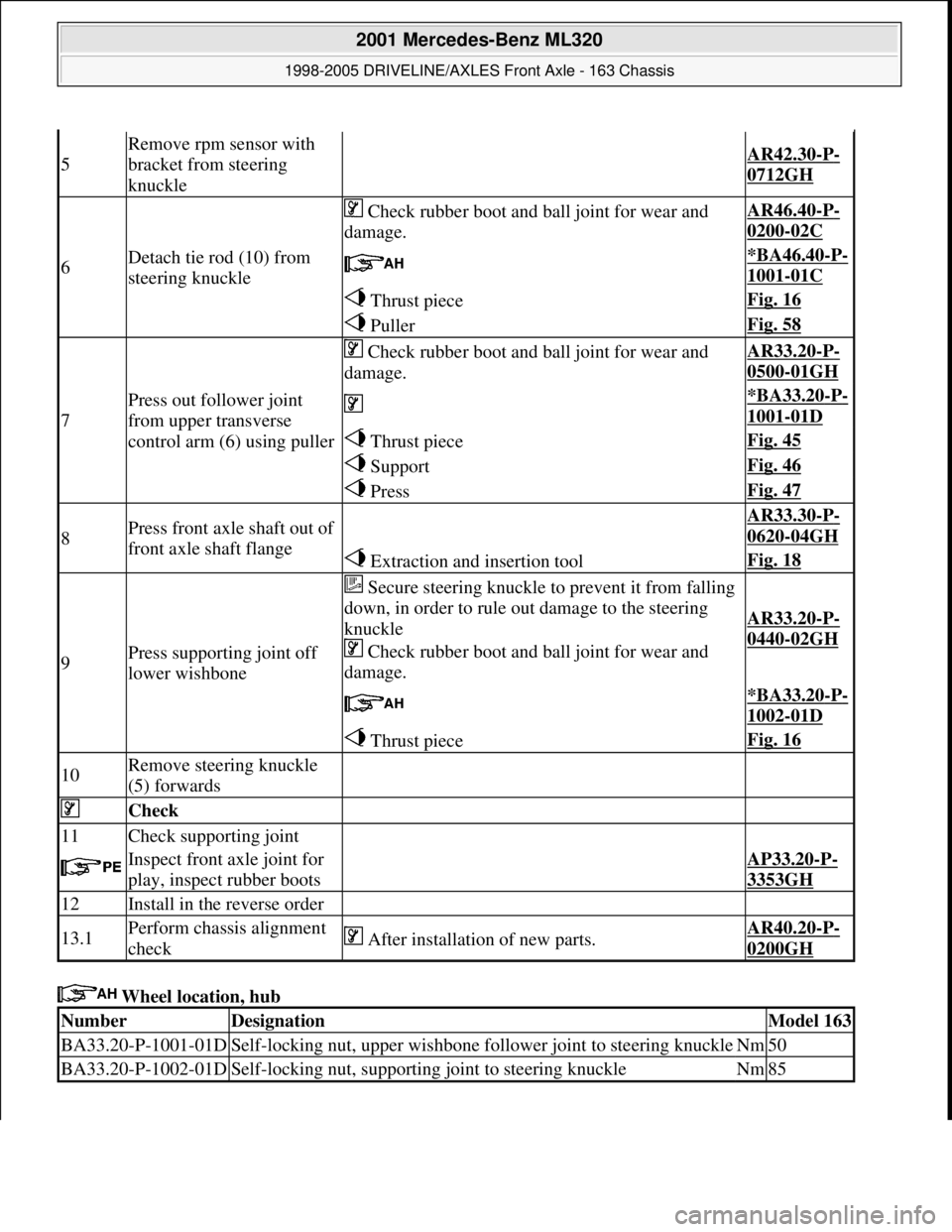
Wheel location, hub
5
Remove rpm sensor with
bracket from steering
knuckle
AR42.30-P-
0712GH
6Detach tie rod (10) from
steering knuckle
Check rubber boot and ball joint for wear and
damage.AR46.40-P-
0200-02C
*BA46.40-P-
1001-01C
Thrust pieceFig. 16
PullerFig. 58
7
Press out follower joint
from upper transverse
control arm (6) using puller
Check rubber boot and ball joint for wear and
damage.AR33.20-P-
0500-01GH
*BA33.20-P-
1001-01D
Thrust pieceFig. 45
SupportFig. 46
PressFig. 47
8Press front axle shaft out of
front axle shaft flange AR33.30-P-
0620-04GH
Extraction and insertion toolFig. 18
9Press supporting joint off
lower wishbone
Secure steering knuckle to prevent it from falling
down, in order to rule out damage to the steering
knuckle
Check rubber boot and ball joint for wear and
damage.
AR33.20-P-
0440-02GH
*BA33.20-P-
1002-01D
Thrust pieceFig. 16
10Remove steering knuckle
(5) forwards
Check
11Check supporting joint
Inspect front axle joint for
play, inspect rubber bootsAP33.20-P-
3353GH
12Install in the reverse order
13.1Perform chassis alignment
check After installation of new parts.AR40.20-P-
0200GH
NumberDesignationModel 163
BA33.20-P-1001-01DSelf-locking nut, upper wishbone follower joint to steering knuckleNm50
BA33.20-P-1002-01DSelf-locking nut, supporting joint to steering knuckleNm85
2001 Mercedes-Benz ML320
1998-2005 DRIVELINE/AXLES Front Axle - 163 Chassis
me
Saturday, October 02, 2010 3:38:22 PMPage 37 © 2006 Mitchell Repair Information Company, LLC.
Page 2571 of 4133
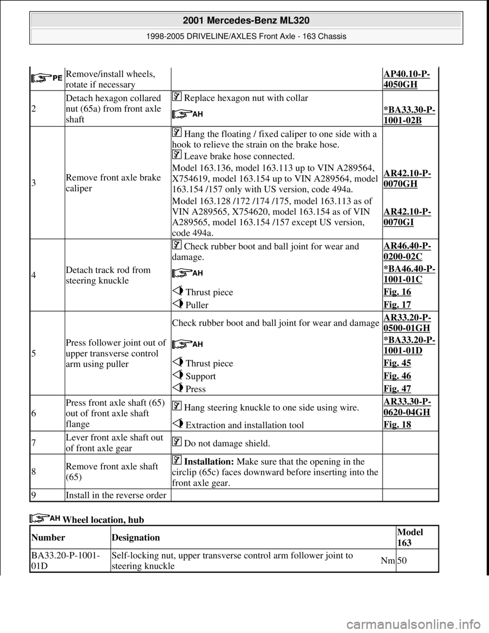
Wheel location, hub
Remove/install wheels,
rotate if necessary AP40.10-P-
4050GH
2
Detach hexagon collared
nut (65a) from front axle
shaft Replace hexagon nut with collar
*BA33.30-P-
1001-02B
3Remove front axle brake
caliper
Hang the floating / fixed caliper to one side with a
hook to relieve the strain on the brake hose.
Leave brake hose connected.
Model 163.136, model 163.113 up to VIN A289564,
X754619, model 163.154 up to VIN A289564, model
163.154 /157 only with US version, code 494a.AR42.10-P-
0070GH
Model 163.128 /172 /174 /175, model 163.113 as of
VIN A289565, X754620, model 163.154 as of VIN
A289565, model 163.154 /157 except US version,
code 494a.
AR42.10-P-
0070GI
4Detach track rod from
steering knuckle
Check rubber boot and ball joint for wear and
damage.AR46.40-P-
0200-02C
*BA46.40-P-
1001-01C
Thrust pieceFig. 16
PullerFig. 17
5
Press follower joint out of
upper transverse control
arm using puller
Check rubber boot and ball joint for wear and damageAR33.20-P-
0500-01GH
*BA33.20-P-
1001-01D
Thrust pieceFig. 45
SupportFig. 46
PressFig. 47
6
Press front axle shaft (65)
out of front axle shaft
flange Hang steering knuckle to one side using wire.AR33.30-P-
0620-04GH
Extraction and installation toolFig. 18
7Lever front axle shaft out
of front axle gear Do not damage shield.
8Remove front axle shaft
(65) Installation: Make sure that the opening in the
circlip (65c) faces downward before inserting into the
front axle gear.
9Install in the reverse order
NumberDesignationModel
163
BA33.20-P-1001-
01DSelf-locking nut, upper transverse control arm follower joint to
steering knuckleNm50
2001 Mercedes-Benz ML320
1998-2005 DRIVELINE/AXLES Front Axle - 163 Chassis
me
Saturday, October 02, 2010 3:38:22 PMPage 52 © 2006 Mitchell Repair Information Company, LLC.
Page 2843 of 4133
Engine version factor (gasoline/diesel)
National factor (The kilometer or mileage is coded in accordance with the national version.)
Distance travelled :
ASSYST is supplied with the 4 wheel speeds from the traction systems control module (N47) over the
CAN for calculating the distance travelled.
Time
ASSYST is supplied with the time information from the clock integrated in the instrument cluster.
ACTIVE SERVICE SYSTEM (ASSYST) SURVEY MODEL/ENGINE/SENSOR/INSTRUMENT CLUSTER - GF00.20-P-0003-
06A
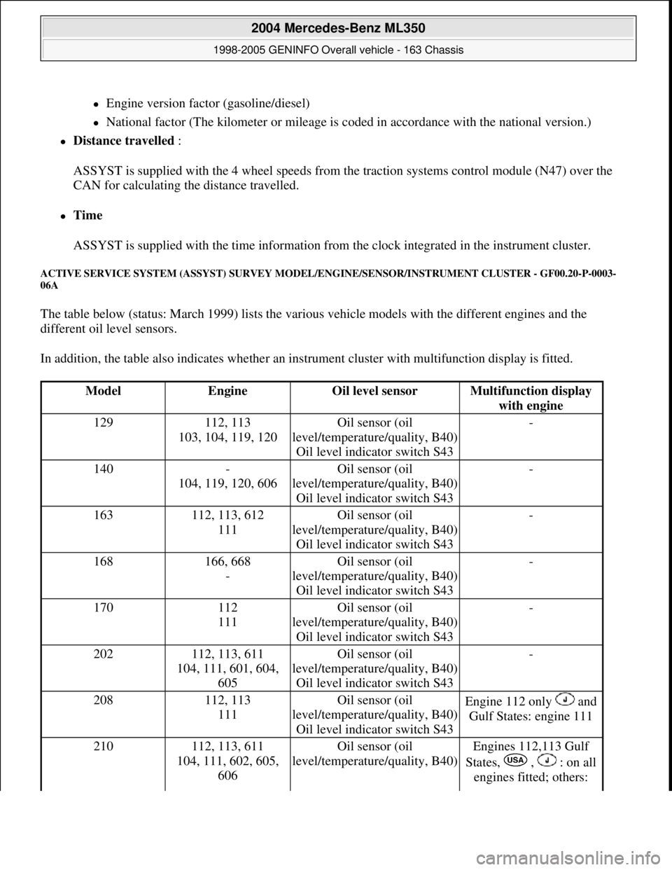
The table below (status: March 1999) lists the various vehicle models with the different engines and the
different oil level sensors.
In addition, the table also indicates whether an instrument cluster with multifunction display is fitted.
ModelEngineOil level sensorMultifunction display
with engine
129112, 113
103, 104, 119, 120Oil sensor (oil
level/temperature/quality, B40)
Oil level indicator switch S43-
140-
104, 119, 120, 606Oil sensor (oil
level/temperature/quality, B40)
Oil level indicator switch S43-
163112, 113, 612
111Oil sensor (oil
level/temperature/quality, B40)
Oil level indicator switch S43-
168166, 668
-Oil sensor (oil
level/temperature/quality, B40)
Oil level indicator switch S43-
170112
111Oil sensor (oil
level/temperature/quality, B40)
Oil level indicator switch S43-
202112, 113, 611
104, 111, 601, 604,
605Oil sensor (oil
level/temperature/quality, B40)
Oil level indicator switch S43-
208112, 113
111Oil sensor (oil
level/temperature/quality, B40)
Oil level indicator switch S43Engine 112 only and
Gulf States: engine 111
210112, 113, 611
104, 111, 602, 605,
606Oil sensor (oil
level/temperature/quality, B40)Engines 112,113 Gulf
States, , : on all
engines fitted; others:
2004 Mercedes-Benz ML350
1998-2005 GENINFO Overall vehicle - 163 Chassis
me
Saturday, October 02, 2010 3:47:47 PMPage 198 © 2006 Mitchell Repair Information Company, LLC.