1997 MERCEDES-BENZ ML430 traction control
[x] Cancel search: traction controlPage 2845 of 4133
After a level has dropped below a warning threshold, the remaining distance or the remaining time is displayed
in text panel (b) and the tool symbol (a) appears in the display (top ill.). In addition, ASSYST features a low
engine oil level display. If the oil level is too low or too high, this appears in text panel (b) and the oil can
symbol (a) is displayed (bottom ill.).
( The illustrations relate to models with multifunction display. For other models, refer to document:
"ASSYST display facilities".)
Service A/B display
All models will feature an automatic display of the service (A or B) by no later than modification year 00/1.
More detailed information is contained in the document displaying service.
Fig. 320: Identifying Service A/B Display
In view of the complexity of the system, ASSYST features its own processor in the instrument cluster.
ASSYST is supplied with the time information from the electronic clock integrated in the instrument cluster.
The other data required are supplied over the CAN dataline by the traction systems control module (N47) and
by the injection system control module (N3).
CAN data required for ASSYST:
wheel speed signals for calculating the vehicle speed and distance (from traction systems control module,
N47)
Coolant temperature (from injection system control module, N3)
Engine oil temperature (from injection system control module, N3)
Oil level (from injection system control module, N3)
Engine speed (from injection system control module, N3)
Load torque (from injection system control module, N3)
Oil correction factor (from injection system control module, N3)
Active service system (ASSYST) GF00.20-P-0003-03A
2004 Mercedes-Benz ML350
1998-2005 GENINFO Overall vehicle - 163 Chassis
me
Saturday, October 02, 2010 3:47:47 PMPage 200 © 2006 Mitchell Repair Information Company, LLC.
Page 3247 of 4133
NOTES ON HANDLING REFRIGERANT R134A - AH83.30-N-0003-01A
Air conditioning with refrigerant R134a
The refrigerant R134a is colorless and odorless.
At normal temperatures it is neither toxic nor flammable, and will not explode in the air, no matter what its
mixing ratio.
The R134a refrigerant may only be used in air conditioning systems for which R134a has been specifically
approved.
The refrigerant R134a must not be mixed with other refrigerants (e.g. R12).
The refrigerant R134a does not contain any chlorofluorocarbons (CFC). In contrast to other refrigerants (e.g.
R12) it is not hazardous to the environment at normal temperatures. The refrigerant R134a does not damage the
earth's ozone layer.
Despite these benefits, refrigerant R134a may only be extracted by experts with suitable extraction, recycling
and filling equipment that includes integral disposal and reprocessing capabilities.
CONDUCT IF AIR CONDITIONING SYSTEM IS DAMAGED OR LEAKING - AH83.30-N-0004-01A
All models
The air conditioning system should never be operated if it is damaged or when there is evidence of refrigerant
loss.
In the event that refrigerant is lost, lubrication can fail. This will lead to damage of the refrigerant compressor.
Evacuate damaged and/or leaking air conditioning refrigerant circuits as quickly as possible using extraction,
processing and recharging equipment with integral disposal and reprocessing capabilities.
PROTECT AIR CONDITIONING CIRCUIT AND COMPONENTS FROM MOISTURE WHEN CARRYING OUT REPAIR
WORK - AH83.30-N-0005-01A
Protect air conditioning circuit and
components from moisture when carrying
out repair work
MODEL 240AH83.30-P-
0005-01H
Protect air conditioning circuit and
components from moisture when carrying
out repair work
MODEL 164, 199, 203, 209, 251 ...AH83.30-P-
0005-01P
Protect air conditioning circuit and
components from moisture when carrying
out repair work
MODEL 199AH83.30-P-
0005-01SLR
Notes on removing and installing the air
conditioner housingMODEL 209, 463 ...AH83.30-P-
0006-01GM
2001 Mercedes-Benz ML320
1998-2005 HVAC Climate Control - 163 Chassis
me
Saturday, October 02, 2010 3:23:14 PMPage 3 © 2006 Mitchell Repair Information Company, LLC.
Page 3343 of 4133
This input information is relayed by the CDI control module (N3/9) to the integrated control module of the
electric engine/AC intake fan with integrated control (M4/7).
Engines 113.942 and 113.981
The all-activity module (AAM) (N10) receives the coolant temperature via the coolant temperature sensor and
the refrigerant pressure via the refrigerant pressure sensor (B12).
This input information is relayed by the all-activity module (AAM) (N10) to the integrated control module of
the engine and AC electric suction fan with integrated control (M4/7)
There the input information is compared with the stored values and, if necessary, the speed of the engine and
AC electric suction fan with integrated control (M4/7) is increased to 100 %.
The engine and AC electric suction fan with integrated control (M4/7) operates with AC switched on and in the
reheat mode for basic ventilation with a capacity of up to 20 %.
The basic ventilation can be switched off under the following conditions:
At an outdoor temperature of < or = 15°C the value of the outdoor temperature is transmitted from the
outside temperature sensor (B10/5) to the AC control module (N19).
The pressure-dependent fan speed remains the same.
At a vehicle speed of > 75 km/h
The vehicle speed value comes from the traction system control module via the instrument cluster (A1)
and CDI control module (N3/9), to the control module integrated in the electric suction fan engine and
AC with integrated control (M4/7). The pressure-dependent fan speed remains the same.
An overrun time of 60 s can be set in order to ensure that the engine and AC electric suction fan with integrated
control (M4/7) will continue to operate even where the refrigerant compressor is temporarily switched off by
the icing protection.
The engine and AC electric suction fan with integrated control (M4/7) has a power rating of 550W.
ELECTRIC FAN, ENGINE/AIR CONDITIONING, LOCATION - GF83.40-P-2118-02GH
The engine and AC electric suction fan with integrated control (M4/7) is located immediately in front of the
condenser.
2001 Mercedes-Benz ML320
1998-2005 HVAC Climate Control - 163 Chassis
me
Saturday, October 02, 2010 3:23:16 PMPage 99 © 2006 Mitchell Repair Information Company, LLC.
Page 3385 of 4133
The in-car temperature sensor (B10/4) is equipped with an aspirator blower which constantly draws air out of
the vehicle interior for the temperature measurement when the ignition is ON . The in-car temperature sensor
(B10/4) records the interior temperature and conveys it to the AAC push-button control module. A comparison
is made there with the setting on the temperature selector and the blend air flap is repositioned depending on the
result of this comparison.
It is connected to the AAC push-button control module via a separate electric cable.
Constant circulation of the interior air at the in-car temperature sensor (B10/4) is achieved by the in-car
temperature sensor aspirator blower (M9) and therefore ensures a high level of control accuracy.
In contrast to the previous suction jet nozzle a high level of control accuracy is ensured by the in-car
temperature sensor aspirator blower (M9).
OUTSIDE AIR TEMPERATURE SENSOR FUNCTION - GF83.57-P-2103-01GH
Function
The resistance of the outside air temperature sensor (B10/5) depends on the ambient temperature and the ground
speed. With an increase in the outside temperature, its resistance decreases. This information is sent to the air
conditioning control module (N19). This information causes a slight lowering or raising of the temperature
selected at the air conditioning control panel.
This achieves an adaptation to the temperature perception of the occupants.
The outside temperature depends on the ground speed, which prevents a value for the outside temperature that is
too high - as may occur when the vehicle is stationary or when traveling slowly, e.g. due to thermal radiation
from the engine - from being sent to the air conditioning control module (N19).
The value of the ground speed is sent from the traction systems control module (N47) via the instrument cluster
(A1) to the air conditioning control module (N19).
When switching the ignition off and on and with speeds lower than 20 km/h the temperature measured last is
used.
OUTSIDE AIR TEMPERATURE SENSOR POSITION - GF83.57-P-2103-02GH
The outside air temperature sensor (B10/5) is located at the front on the air inlet of the evaporator housing.
2001 Mercedes-Benz ML320
1998-2005 HVAC Climate Control - 163 Chassis
me
Saturday, October 02, 2010 3:23:17 PMPage 141 © 2006 Mitchell Repair Information Company, LLC.
Page 3482 of 4133

GF54.30-P-3003A
Indicator/warning messages triggered via CAN data buses, function
24.10.96
MODEL
129, 140 as of 1.6.96,
163, 168, 170,
202 as of 1.8.96,
208 up to 31.7.99,
210 as of 1.6.96 up to 30.6.99
Indicator and warning displays triggered via CAN
Low brake fluid level/parking brake indicator lamp (A1e7)
The parking brake signal comes from the traction system
control module.
The brake fluid signal comes directly from the switch (S11)
(except model 163).
Brake pad wear indicator lamp (A1e6)
The parking brake signal comes from the traction system
control module (N47)
Low engine oil level indicator lamp (A1e12)
The oil level signal comes from the injection system control
module (N3).
For vehicles with ASSYST, also refer to document: ASSYST
engine oil monitoring.
Preglow indicator lamp (A1e16)
The signal comes directly from the injection system control
module (N3).
Coolant level and temperature warning lamp (A1e11) model 168
only as of 9.99
The coolant temperature signal comes from the injection
system control module (N3)
-----------------------------------------------------------------------------------------
ABS MIL (A1e17)
The parking brake signal comes from the traction system
control module (N47).
"CHECK ENGINE" MIL (A1e26),
I
only
The signal comes from the injection system control module (N3)
ETS (A1e35) or ASR (A1e22) or ESP (A1e42) MIL
Lamp illuminated if there is a fault in the respective system.
The signal comes from the traction system control module
(N47).
ETS (A1e36) or ASR (A1e21) or ESP (A1e41) warning lamp
The lamp indicates that the respective system is active.
The signal comes from the traction system control module
(N47).
-----------------------------------------------------------------------------------------
Severe leak warning (
I
as of 97 only)
The fuel reserve indicator lamp (A1e4) flashes. The signal
comes from the injection system control module (N3).
The warning takes place at the earliest 30 minutes after cold
start with the engine idling and the vehicle stationary.
Also refer to document: Purge system with leak test, function
Fog lamps indicator lamp (A1e57), model 163 only except
I
)
The signal comes from the All-activity module (AAM, N10)
"LOW RANGE" indicator lamp (A1e53), model 163 only
The signal comes from the transfer case control module (N78)
Active service system (ASSYST)
Engines 112, 113, 611 (engines with oil
sensor)
GF00.20-P-2009A
Engine oil monitoring, function
Model 210 as of 01.03.97 with engine M111,
OM602, OM604, OM605 and OM606
As of 06.97 models 129, 140, 170, 202 except
engines 112, 113, 611
(Valid for engines with low oil level switch).
GF00.20-P-2009B
Displaying coolant temperature, function
Model 168 as of 9.99
GF54.30-P-3020GC
Purge system with leak test, function
GF47.30-P-3016L
Bus systems, overall function
GF54.00-P-0004A
Copyright DaimlerChrysler AG 04.06.2006 CD-Ausgabe G/10/04 . This WIS print-out will not be recorde
d by Modification services.
Page 1
Page 3496 of 4133

AD54.30-P-5000GH
Instrument cluster (IC) diagnosis troubleshooting
10.4.97
MODEL
163
Connection and use of test equipment
AD00.00-P-1000AZ
Instrument cluster diagnosis, previous
knowledge
AD54.30-P-2000GH
Explanatory notes on diagnosis
troubleshooting chart IC
AD54.30-P-5000-01GH
Display instruments controlled via CAN
troubleshooting chart IC
AD54.30-P-5000-02A
Display instruments controlled directly,
troubleshooting chart IC
AD54.30-P-5000-03A
Troubleshooting
Complaint
Possible cause
Notes
Remedy/Test step
Instrument cluster (A1) completely inoperative
Voltage supply, instrument cluster (A1)
AD54.30-P-6000-01GH
Malfunction indicator lamps or indicator lamps
inoperative
Voltage supply, instrument cluster (A1)
AD54.30-P-6000-01GH
HHT and instrument cluster cannot
communicate
Cables, instrument cluster (A1)
AD54.30-P-6000-02GH
Low brake fluid level/parking brake indicator
lamp, brake pad wear indicator lamp, ABS
MIL, malfunction indicator lamp (ETS, ASR,
ESP) come on together and speedometer
remains on lower stop.
Traction system control module (N47)
AD42.35-P-1001BZ
RPM counter, engine coolant gauge remain
on the lower stop and the low engine oil level
indicator lamp comes on.
Injection system control module (N3)
AD07.61-P-1000AZ
Low brake fluid level/parking brake indicator
lamp, brake pad wear indicator lamp, low
engine oil level indicator lamp, ABS MIL,
malfunction indicator lamp (ETS, ASR, ESP)
come on together and RPM counter, engine
coolant gauge and speedometer remain on
lower stop.
CAN faulty
AD54.30-P-6000-04GH
AD54.30-P-6000-05GH
Steering lock warning lamp (A1e40) is
continuously illuminated or is inoperative.
Cables,
steering lock switch (S97/1)
AD54.30-P-6000-06GH
Coolant level indicator disrupted
Cables,
Coolant level indicator electronic switch (S41)
Model 163 as of 3.98
AD54.30-P-6000-42GH
Copyright DaimlerChrysler AG 05.06.2006 CD-Ausgabe G/10/04 . This WIS print-out will not be recorde
d by Modification services.
Page 1
Page 3497 of 4133
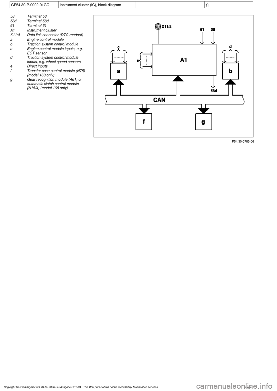
GF54.30-P-0002-01GC
Instrument cluster (IC), block diagram
n
P54.30-0785-06
58
Terminal 58
58d
Terminal 58d
61
Terminal 61
A1
Instrument cluster
X11/4
Data link connector (DTC readout)
a
Engine control module
b
Traction system control module
c
Engine control module inputs, e.g.
ECT sensor
d
Traction system control module
inputs, e.g. wheel speed sensors
e
Direct inputs
f
Transfer case control module (N78)
(model 163 only)
g
Gear recognition module (A61) or
automatic clutch control module
(N15/4) (model 168 only)
Copyright DaimlerChrysler AG 04.06.2006 CD-Ausgabe G/10/04 . This WIS print-out will not be recorde
d by Modification services.
Page 1
Page 3715 of 4133

AD00.00-P-2000-02C
Assignment of data link connector
P07.00-0323-10
X11/22
Data link connector
1
Electronic ignition/starter switch control module (model
168)
2 -
3
TNA signal (gasoline)
3
TD signal (diesel)
4
Circuit 31 (ground)
5
Circuit 31 (electronics ground)
6
CAN interior bus (H)
7
ME
Motor electronics (ME-SFI)
8
Circuit 87 voltage
9
ABS
Anti-lock brake system (model 168)
9
ETS
Electronic traction system (model 163)
9
ASR
Acceleration slip regulation (model 168)
9
ESP
Electronic Stability Program
10
-
11 ETC
Electronic transmission control
11
FTC
Front transmission control (model 168)
11
Automatic clutch (model 168)
12
AAM
All activity module
12
RD
Radio Audio 10, Audio 30, and Audio 30 APS with D2B
(model 168)
13
AB
Airbag/emergency tensioning retractor
14
CAN interior bus (L)
15 IC
Instrument cluster
16
Circuit 30 voltage 30
Copyright DaimlerChrysler AG 05.06.2006 CD-Ausgabe G/10/04 . This WIS print-out will not be recorde
d by Modification services.
Page 1