1997 MERCEDES-BENZ ML430 wiring
[x] Cancel search: wiringPage 1499 of 4133
NOTES ON NAVIGATION SYSTEM TRAFFICSTAR - AH82.61-P-0001-03A
Models 129, 140, 163, 168, 170, 202, 208, 210
Customer information on GPS antenna installation location
On all sedans and coupes, the GPS antenna can be mounted on the rear shelf as an alternative to the instrument
panel.
TrafficStar customer information
The TrafficStar navigation system is available in two versions from the Becker Company:
1. Mat black cover
2. Precious wood cover, burr walnut (Avant-
garde)
conversion for Tele Aid
emergency call system
Notes regarding the Tele-Aid
emergency call systemMODEL 463 ...AH82.95-P-0001-
01GA
Notes regarding the Tele-Aid
emergency call systemMODEL 199AH82.95-P-0001-
01SLR
Notes on Tele Aid
emergency call system
control module changeMODEL 140 with CODE
(348) TELE AID
emergency call systemAH82.95-P-0001-02A
Cleaning plastic cover plates
of lampsMODEL 168, 169, 171,
199, 203, 204, 208, 209,
210, 211, 215, 216, 219,
220, 221, 230, 240, 245.2AH82.10-P-1002-01A
Cleaning plastic cover plates
of lampsMODEL 454.0AH82.10-P-1002-
01FF
Notes on installation of
wiring harnesses in roof areaMODEL 203.0AH82.25-P-1000-01P
Notes on avoiding damage to
fiber optic cables during
repair workMODEL 164, 169, 211,
216, 221, 245, 251, 454 ...AH82.60-P-0001-
05AK
Notes on avoiding damage to
fiber optic cables during
repair workMODEL 219.3 with Media
Oriented System Transport
(MOST)AH82.60-P-0001-
05TX
Notes on fiber optic cableMODEL 129, 163, 168,
170, 202, 203, 208, 209,
210, 215, 220, 230, 414,
463 ...AH82.70-P-0001-02A
2001 Mercedes-Benz ML320
1998-2005 ACCESSORIES & BODY, CAB Electrical System - Body - 163 Chassis
me
Saturday, October 02, 2010 3:30:04 PMPage 4 © 2006 Mitchell Repair Information Company, LLC.
Page 1500 of 4133
Notes on installation of GPS antenna
The GPS antenna should be installed only in a vertical position with a maximum deviation of 10° from
horizontal.
The GPS antenna should always have a free view of the sky. Thermal insulated windows can significantly
reduce the function of the GPS antenna.
When installing the GPS antenna, always ensure that the arched surface points away from the vehicle.
Changing the installation location inside of the vehicle after the system is put into operation has no effect on the
GPS reception.
NOTES ON RADIO CONNECTOR PIN ASSIGNMENT - AH82.61-P-0001-05A
Model 163
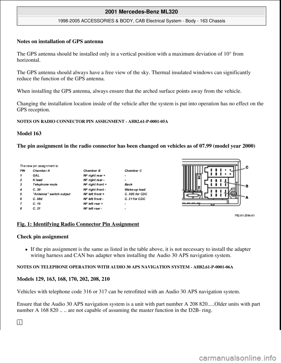
The pin assignment in the radio connector has been changed on vehicles as of 07.99 (model year 2000)
Fig. 1: Identifying Radio Connector Pin Assignment
Check pin assignment
If the pin assignment is the same as listed in the table above, it is not necessary to install the adapter
wiring harness and CAN bus adapter when installing the Audio 30 APS navigation system.
NOTES ON TELEPHONE OPERATION WITH AUDIO 30 APS NAVIGATION SYSTEM - AH82.61-P-0001-06A
Models 129, 163, 168, 170, 202, 208, 210
Vehicles with telephone code 316 or 317 can be retrofitted with an Audio 30 APS navigation system.
Ensure that the Audio 30 APS navigation system is a unit with part number A 208 820.....Older units with part
number A 168 820 .. .. are not capable of assuming the master function in the D2B- ring.
2001 Mercedes-Benz ML320
1998-2005 ACCESSORIES & BODY, CAB Electrical System - Body - 163 Chassis
me
Saturday, October 02, 2010 3:30:04 PMPage 5 © 2006 Mitchell Repair Information Company, LLC.
Page 1502 of 4133
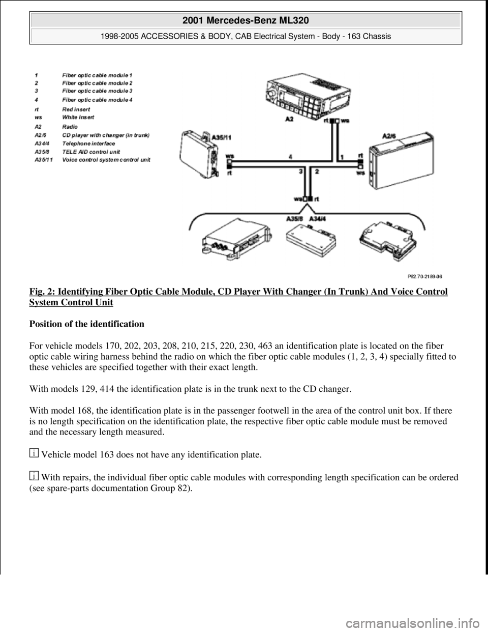
Fig. 2: Identifying Fiber Optic Cable Module, CD Player With Changer (In Trunk) And Voice Control
System Control Unit
Position of the identification
For vehicle models 170, 202, 203, 208, 210, 215, 220, 230, 463 an identification plate is located on the fiber
optic cable wiring harness behind the radio on which the fiber optic cable modules (1, 2, 3, 4) specially fitted to
these vehicles are specified together with their exact length.
With models 129, 414 the identification plate is in the trunk next to the CD changer.
With model 168, the identification plate is in the passenger footwell in the area of the control unit box. If there
is no length specification on the identification plate, the respective fiber optic cable module must be removed
and the necessary length measured.
Vehicle model 163 does not have any identification plate.
With repairs, the individual fiber optic cable modules with corresponding length specification can be ordered
(see spare-parts documentation Group 82).
2001 Mercedes-Benz ML320
1998-2005 ACCESSORIES & BODY, CAB Electrical System - Body - 163 Chassis
me
Saturday, October 02, 2010 3:30:04 PMPage 7 © 2006 Mitchell Repair Information Company, LLC.
Page 1503 of 4133
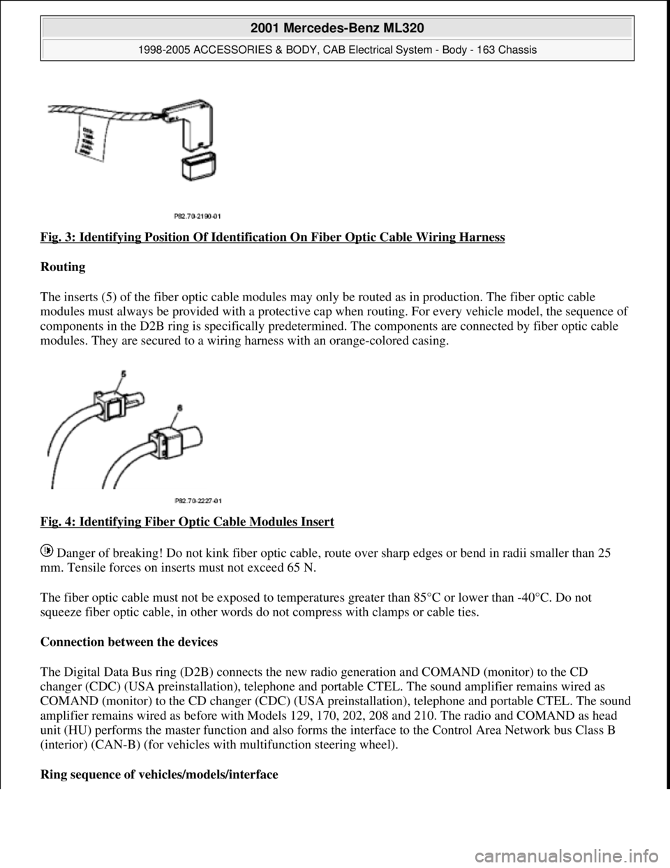
Fig. 3: Identifying Position Of Identification On Fiber Optic Cable Wiring Harness
Routing
The inserts (5) of the fiber optic cable modules may only be routed as in production. The fiber optic cable
modules must always be pr ovided with a protective cap when routing. For every vehicle model, the sequence of
components in the D2B ring is specifically predetermi ned. The components are connected by fiber optic cable
modules. They are secured to a wiring ha rness with an orange-colored casing.
Fig. 4: Identifying Fiber Optic Cable Modules Insert
Danger of breaking! Do not kink fiber optic cable, route over sharp edges or be nd in radii smaller than 25
mm. Tensile forces on inserts must not exceed 65 N.
The fiber optic cable must not be exposed to temperat ures greater than 85°C or lower than -40°C. Do not
squeeze fiber optic cable, in other words do not compress with clamps or cable ties.
Connection between the devices
The Digital Data Bus ring (D2B) connects the new ra dio generation and COMAND (monitor) to the CD
changer (CDC) (USA preinstallati on), telephone and portable CTEL. The sound amplifier remains wired as
COMAND (monitor) to the CD changer (CDC) (USA preinstallation), telephone and portable CTEL. The sound
amplifier remains wired as befo re with Models 129, 170, 202, 208 and 210. The radio and COMAND as head
unit (HU) performs the master function and also forms the interface to the Control Area Network bus Class B
(interior) (CAN-B) (for vehicles wi th multifunction steering wheel).
Ring sequence of vehi cles/models/interface
2001 Mercedes-Benz ML320
1998-2005 ACCESSORIES & BODY, CAB Electr ical System - Body - 163 Chassis
me
Saturday, October 02, 2010 3:30:04 PMPage 8 © 2006 Mitchell Repair Information Company, LLC.
Page 1506 of 4133
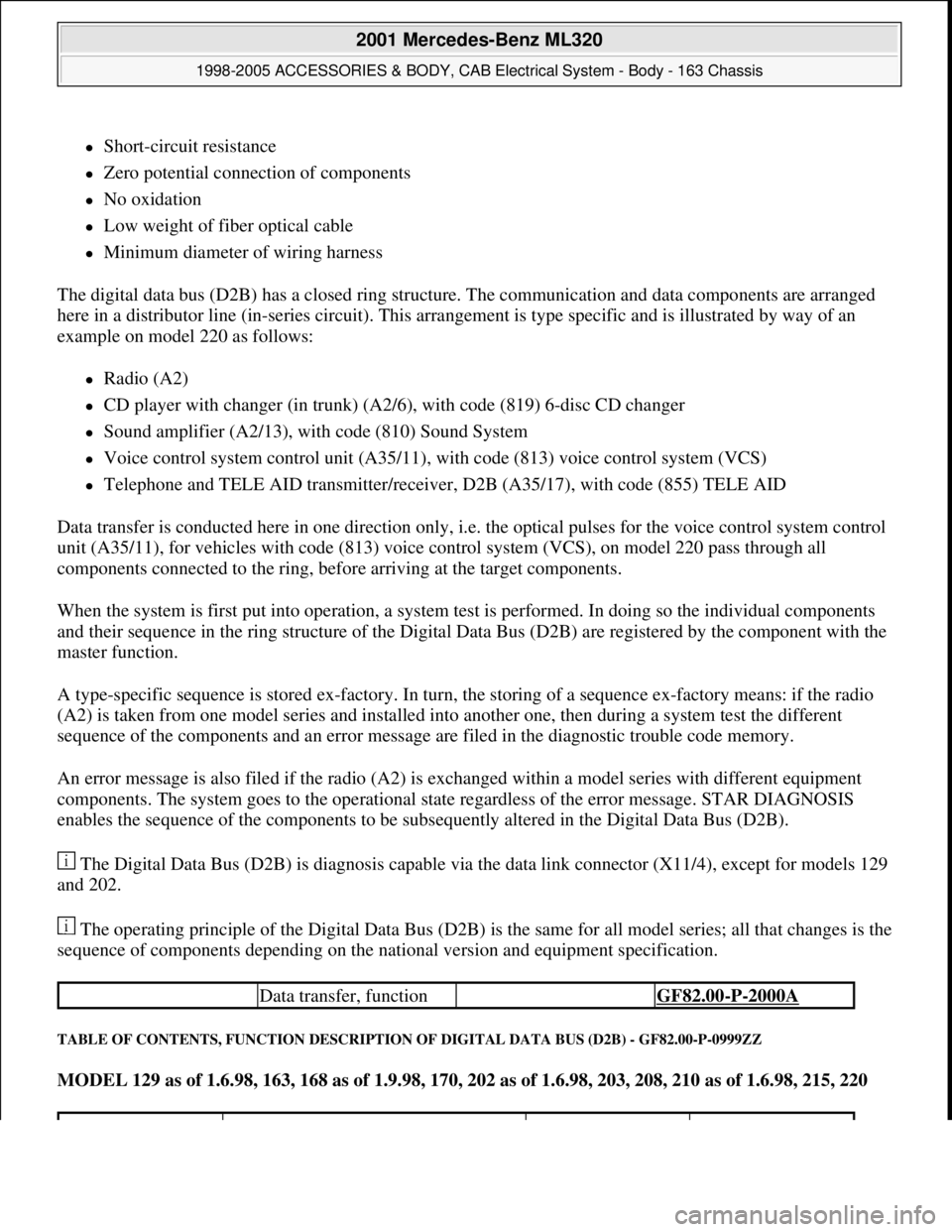
Short-circuit resistance
Zero potential connection of components
No oxidation
Low weight of fiber optical cable
Minimum diameter of wiring harness
The digital data bus (D2B) has a closed ring structure. The communication and data components are arranged
here in a distributor line (in-series circuit). This arrangement is type specific and is illustrated by way of an
example on model 220 as follows:
Radio (A2)
CD player with changer (in trunk) (A2/6), with code (819) 6-disc CD changer
Sound amplifier (A2/13), with code (810) Sound System
Voice control system control unit (A35/11), with code (813) voice control system (VCS)
Telephone and TELE AID transmitter/receiver, D2B (A35/17), with code (855) TELE AID
Data transfer is conducted here in one direction only, i.e. the optical pulses for the voice control system control
unit (A35/11), for vehicles with code (813) voice control system (VCS), on model 220 pass through all
components connected to the ring, before arriving at the target components.
When the system is first put into operation, a system test is performed. In doing so the individual components
and their sequence in the ring structure of the Digital Data Bus (D2B) are registered by the component with the
master function.
A type-specific sequence is stored ex-factory. In turn, the storing of a sequence ex-factory means: if the radio
(A2) is taken from one model series and installed into another one, then during a system test the different
sequence of the components and an error message are filed in the diagnostic trouble code memory.
An error message is also filed if the radio (A2) is exchanged within a model series with different equipment
components. The system goes to the operational state regardless of the error message. STAR DIAGNOSIS
enables the sequence of the components to be subsequently altered in the Digital Data Bus (D2B).
The Digital Data Bus (D2B) is diagnosis capable via the data link connector (X11/4), except for models 129
and 202.
The operating principle of the Digital Data Bus (D2B) is the same for all model series; all that changes is the
sequence of components depending on the national version and equipment specification.
TABLE OF CONTENTS, FUNCTION DESCRIPTION OF DIGITAL DATA BUS (D2B) - GF82.00-P-0999ZZ
MODEL 129 as of 1.6.98, 163, 168 as of 1.9.98, 170, 202 as of 1.6.98, 203, 208, 210 as of 1.6.98, 215, 220
Data transfer, function GF82.00-P-2000A
2001 Mercedes-Benz ML320
1998-2005 ACCESSORIES & BODY, CAB Electrical System - Body - 163 Chassis
me
Saturday, October 02, 2010 3:30:04 PMPage 11 © 2006 Mitchell Repair Information Company, LLC.
Page 1664 of 4133
![MERCEDES-BENZ ML430 1997 Complete Repair Manual MODEL 163 with CODE (259) Radio Premium with Bose sound system
Parts ordering notes
PROGRAM CHANGE ALTHOUGH RDS [RADIO DATA SYSTEM] AND REGIONALIZATION ARE SWITCHED ON -
AF82.60-P-1062A
MODEL 129, MERCEDES-BENZ ML430 1997 Complete Repair Manual MODEL 163 with CODE (259) Radio Premium with Bose sound system
Parts ordering notes
PROGRAM CHANGE ALTHOUGH RDS [RADIO DATA SYSTEM] AND REGIONALIZATION ARE SWITCHED ON -
AF82.60-P-1062A
MODEL 129,](/manual-img/4/57307/w960_57307-1663.png)
MODEL 163 with CODE (259) Radio Premium with Bose sound system
Parts ordering notes
PROGRAM CHANGE ALTHOUGH RDS [RADIO DATA SYSTEM] AND REGIONALIZATION ARE SWITCHED ON -
AF82.60-P-1062A
MODEL 129, 140, 163, 168, 170, 171, 202, 203, 208, 209, 210, 211, 215, 220, 230, 463 with RDS radio
Damage codeCauseRemedy
Speaker wires picking up
interference noise from
surrounding wiring1 Remove radioAR82.60-P-7502EA
2 Remove upper center
console storage
compartment
3 Remove lower dash
panel below steering
columnAR68.10-P-1500GH
4 Install sound system
jumper harness
AF82.60-P-1010-01AG
5 Reinstall in opposite
order
Part no.DesignationQuantity
163 540 98 05Jumper harness for Bose sound
system1
Damage codeCauseRemedy
Station change without
obvious cause.
Some radio stations
which had originally
transmitted regional
identification have been
transmitting the RDS
signals without regional
identification for some
time.
Without regional
identification it is no
longer possible to
separate stations with the
same station name which
transmit different
programs.1 Point out the facts to
the customer.
Do not replace any
devices, state of the art
engineering.
2001 Mercedes-Benz ML320
1998-2005 ACCESSORIES & BODY, CAB Electrical System - Body - 163 Chassis
me
Saturday, October 02, 2010 3:30:06 PMPage 169 © 2006 Mitchell Repair Information Company, LLC.
Page 1682 of 4133
SELF-DIAGNOSTIC SYSTEM
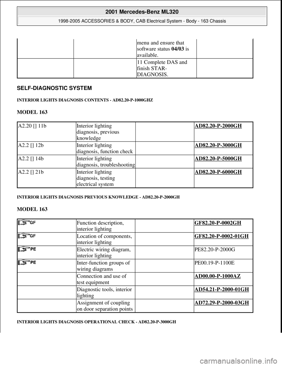
INTERIOR LIGHTS DIAGNOSIS CONTENTS - AD82.20-P-1000GHZ
MODEL 163
INTERIOR LIGHTS DIAGNOSIS PREVIOUS KNOWLEDGE - AD82.20-P-2000GH
MODEL 163
INTERIOR LIGHTS DIAGNOSIS OPERATIONAL CHECK - AD82.20-P-3000GH
menu and ensure that
software status 04/03 is
available.
11 Complete DAS and
finish STAR-
DIAGNOSIS.
A2.20 [] 11bInterior lighting
diagnosis, previous
knowledge AD82.20-P-2000GH
A2.2 [] 12bInterior lighting
diagnosis, function check AD82.20-P-3000GH
A2.2 [] 14bInterior lighting
diagnosis, troubleshooting AD82.20-P-5000GH
A2.2 [] 21bInterior lighting
diagnosis, testing
electrical system AD82.20-P-6000GH
Function description,
interior lighting GF82.20-P-0002GH
Location of components,
interior lighting GF82.20-P-0002-01GH
Electric wiring diagram,
interior lighting PE82.20-P-2000G
Inter-function groups of
wiring diagrams PE00.19-P-1100E
Connection and use of
test equipment AD00.00-P-1000AZ
Diagnostic tools, interior
lighting AD54.21-P-2000-01GH
Assignment of coupling
on door separation points AD72.29-P-2000-03GH
2001 Mercedes-Benz ML320
1998-2005 ACCESSORIES & BODY, CAB Electrical System - Body - 163 Chassis
me
Saturday, October 02, 2010 3:30:07 PMPage 187 © 2006 Mitchell Repair Information Company, LLC.
Page 1688 of 4133
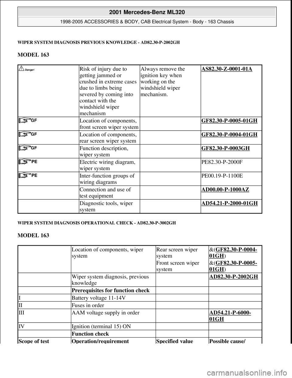
WIPER SYSTEM DIAGNOSIS PREVIOUS KNOWLEDGE - AD82.30-P-2002GH
MODEL 163
WIPER SYSTEM DIAGNOSIS OPERATIONAL CHECK - AD82.30-P-3002GH
MODEL 163
Risk of injury due to
getting jammed or
crushed in extreme cases
due to limbs being
severed by coming into
contact with the
windshield wiper
mechanismAlways remove the
ignition key when
working on the
windshield wiper
mechanism.AS82.30-Z-0001-01A
Location of components,
front screen wiper system GF82.30-P-0005-01GH
Location of components,
rear screen wiper system GF82.30-P-0004-01GH
Function description,
wiper system GF82.30-P-0003GH
Electric wiring diagram,
wiper system PE82.30-P-2000F
Inter-function groups of
wiring diagrams PE00.19-P-1100E
Connection and use of
test equipment AD00.00-P-1000AZ
Diagnostic tools, wiper
system AD54.21-P-2000-01GH
Location of components, wiper
systemRear screen wiper
system&(GF82.30-P-0004-
01GH)
Front screen wiper
system&(GF82.30-P-0005-
01GH)
Wiper system diagnosis, previous
knowledge AD82.30-P-2002GH
Prerequisites for function check
IBattery voltage 11-14V
IIFuses in order
IIIAAM voltage supply in order AD54.21-P-6000-
01GH
IVIgnition (terminal 15) ON
Function check
Scope of test Operation/requirement Specified value Possible cause/
2001 Mercedes-Benz ML320
1998-2005 ACCESSORIES & BODY, CAB Electrical System - Body - 163 Chassis
me
Saturday, October 02, 2010 3:30:07 PMPage 193 © 2006 Mitchell Repair Information Company, LLC.