Page 1805 of 4133
Fig. 211: Identifying Fiber Optical Cable Components
Cover on left under the instrument panel removed for a better display
Fig. 212: Identifying Exchange D2 B
-Wiring Harness And Heater Housing
Remove
Notes on fiber optic
cableModels 129,163, 168, 170, 202,
203, 208, 209,
210,215,220,230,463AH82.70-P-0001-02A
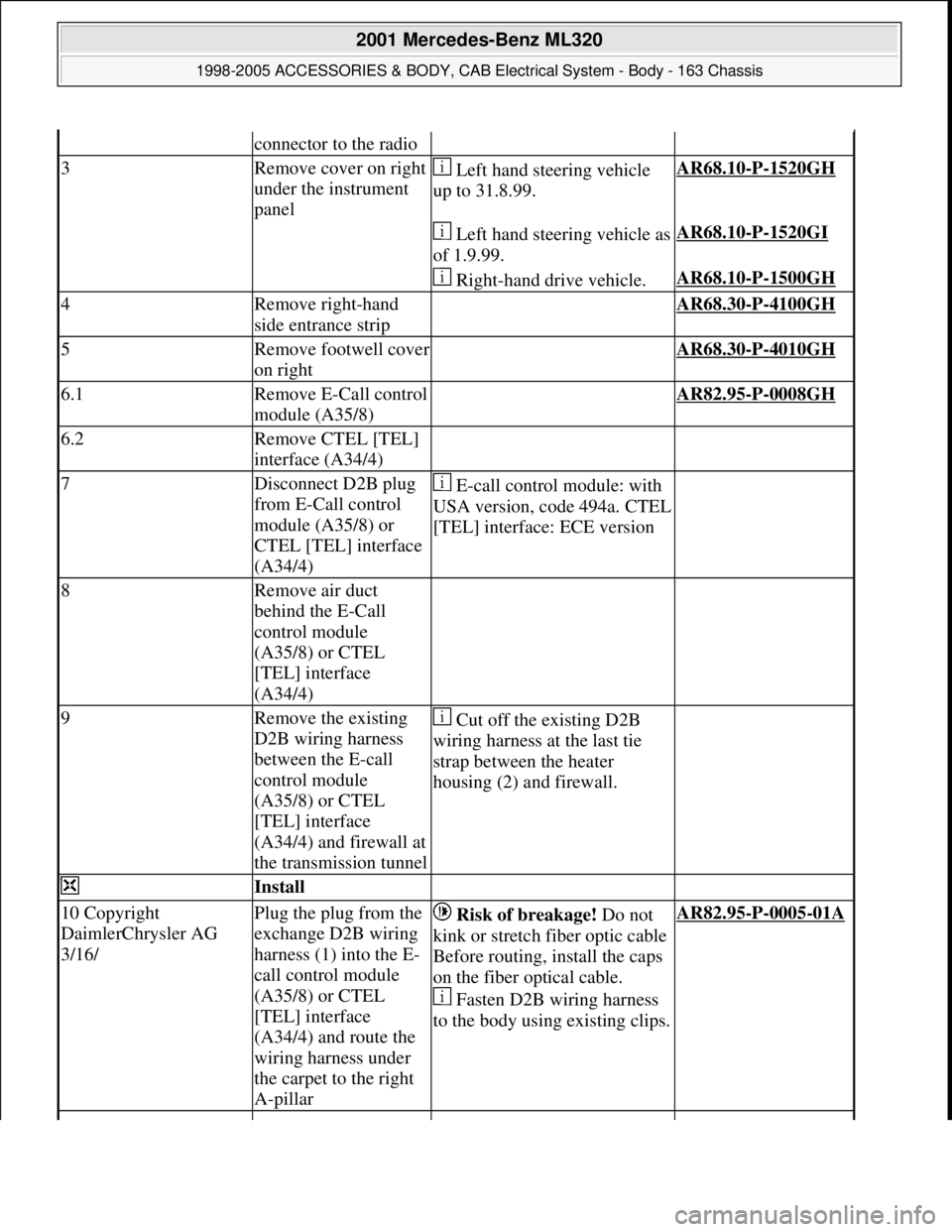
1Remove radio AR82.60-P-7502EA
2Cut the existing D2B
wiring harness as far as
possible away from the
2001 Mercedes-Benz ML320
1998-2005 ACCESSORIES & BODY, CAB Electr ical System - Body - 163 Chassis
me
Saturday, October 02, 2010 3:30:10 PMPage 310 © 2006 Mitchell Repair Information Company, LLC.
Page 1806 of 4133

connector to the radio
3Remove cover on right
under the instrument
panel Left hand steering vehicle
up to 31.8.99.AR68.10-P-1520GH
Left hand steering vehicle as
of 1.9.99.AR68.10-P-1520GI
Right-hand drive vehicle.AR68.10-P-1500GH
4Remove right-hand
side entrance strip AR68.30-P-4100GH
5Remove footwell cover
on right AR68.30-P-4010GH
6.1Remove E-Call control
module (A35/8) AR82.95-P-0008GH
6.2Remove CTEL [TEL]
interface (A34/4)
7Disconnect D2B plug
from E-Call control
module (A35/8) or
CTEL [TEL] interface
(A34/4) E-call control module: with
USA version, code 494a. CTEL
[TEL] interface: ECE version
8Remove air duct
behind the E-Call
control module
(A35/8) or CTEL
[TEL] interface
(A34/4)
9Remove the existing
D2B wiring harness
between the E-call
control module
(A35/8) or CTEL
[TEL] interface
(A34/4) and firewall at
the transmission tunnel Cut off the existing D2B
wiring harness at the last tie
strap between the heater
housing (2) and firewall.
Install
10 Copyright
DaimlerChrysler AG
3/16/Plug the plug from the
exchange D2B wiring
harness (1) into the E-
call control module
(A35/8) or CTEL
[TEL] interface
(A34/4) and route the
wiring harness under
the carpet to the right
A-pillar Risk of breakage! Do not
kink or stretch fiber optic cable
Before routing, install the caps
on the fiber optical cable.
Fasten D2B wiring harness
to the body using existing clips.AR82.95-P-0005-01A
2001 Mercedes-Benz ML320
1998-2005 ACCESSORIES & BODY, CAB Electrical System - Body - 163 Chassis
me
Saturday, October 02, 2010 3:30:10 PMPage 311 © 2006 Mitchell Repair Information Company, LLC.
Page 1807 of 4133

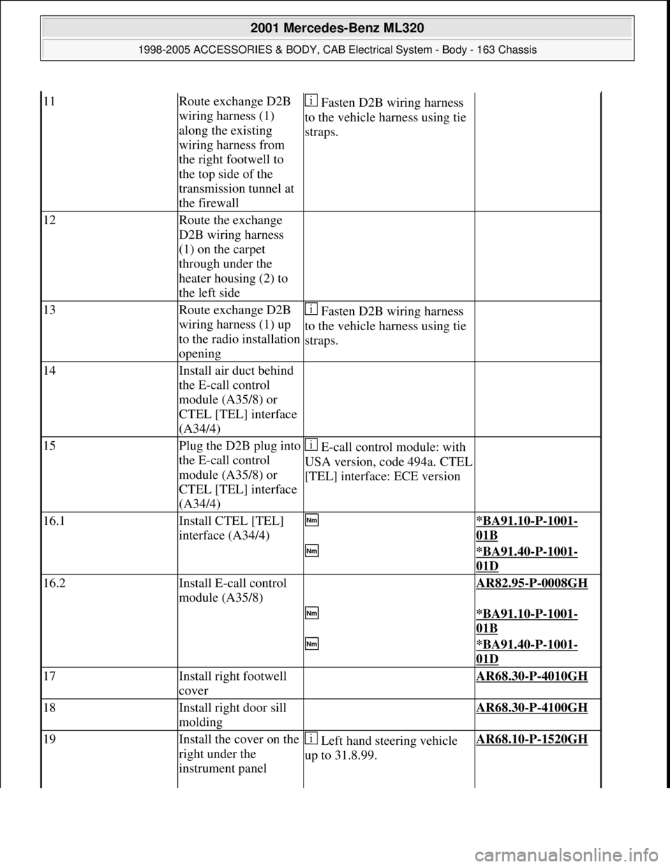
11Route exchange D2B
wiring harness (1)
along the existing
wiring harness from
the right footwell to
the top side of the
transmission tunnel at
the firewall Fasten D2B wiring harness
to the vehicle harness using tie
straps.
12Route the exchange
D2B wiring harness
(1) on the carpet
through under the
heater housing (2) to
the left side
13Route exchange D2B
wiring harness (1) up
to the radio installation
opening Fasten D2B wiring harness
to the vehicle harness using tie
straps.
14Install air duct behind
the E-call control
module (A35/8) or
CTEL [TEL] interface
(A34/4)
15Plug the D2B plug into
the E-call control
module (A35/8) or
CTEL [TEL] interface
(A34/4) E-call control module: with
USA version, code 494a. CTEL
[TEL] interface: ECE version
16.1Install CTEL [TEL]
interface (A34/4) *BA91.10-P-1001-
01B
*BA91.40-P-1001-
01D
16.2Install E-call control
module (A35/8) AR82.95-P-0008GH
*BA91.10-P-1001-
01B
*BA91.40-P-1001-
01D
17Install right footwell
cover AR68.30-P-4010GH
18Install right door sill
molding AR68.30-P-4100GH
19Install the cover on the
right under the
instrument panel Left hand steering vehicle
up to 31.8.99.AR68.10-P-1520GH
2001 Mercedes-Benz ML320
1998-2005 ACCESSORIES & BODY, CAB Electrical System - Body - 163 Chassis
me
Saturday, October 02, 2010 3:30:10 PMPage 312 © 2006 Mitchell Repair Information Company, LLC.
Page 1808 of 4133
Front seats
Seat belts/emergency tensioning retractors
FIBER OPTICAL CABLE (D2B) REPLACE COMPLETE (AFTER TESTING) - AR82.70-P-0005GJ
MODEL 163.113 /154 /174 #A as of 289565, 163.113 #X as of 754620, 163.128 /157 /175 with CODE (810)
Sound system
Left hand steering vehicle as
of 1.9.99.AR68.10-P-1520GI
Right-hand drive vehicle.AR68.10-P-1500GH
20Plug D2B plug from
exchange D2B wiring
harness (1) into radio
21Install radio AR82.60-P-7502EA
NumberDesignationModel Series 163
BA91.10-P-1001-01BBolt of seating mounting
bracket to vehicle floorNm40
NumberDesignation
Model 163 up to
08/99Model 163 as of
09/99
BA91.40-P-1001-
01DScrew on belt end
fittingNm3535
2001 Mercedes-Benz ML320
1998-2005 ACCESSORIES & BODY, CAB Electrical System - Body - 163 Chassis
me
Saturday, October 02, 2010 3:30:10 PMPage 313 © 2006 Mitchell Repair Information Company, LLC.
Page 1809 of 4133
Fig. 213: Identifying Fiber Optical Cable (D2B) Components
Fig. 214: Identifying Fiber Op tical Cable (D2B) Components
Fig. 215: Identifying Exchange D2B Wi ring Harness And Heater Housing
Remove
Notes on fiber optic cableModels 129, 163, 168, 170,
202, 203, 208, 209,
210,215,220,230,463AH82.70-P-0001-
02A
1Remove radio AR82.60-P-7502EA
2Cut through the existing D2B
wiring harness as far as
possible from the connector on
2001 Mercedes-Benz ML320
1998-2005 ACCESSORIES & BODY, CAB Electr ical System - Body - 163 Chassis
me
Saturday, October 02, 2010 3:30:10 PMPage 314 © 2006 Mitchell Repair Information Company, LLC.
Page 1810 of 4133

REMOVE/INSTALL ANTENNA SPLITTER - AR82.70-P-8953GH
MODEL 163.113 /136 /154 /157 /172 /174
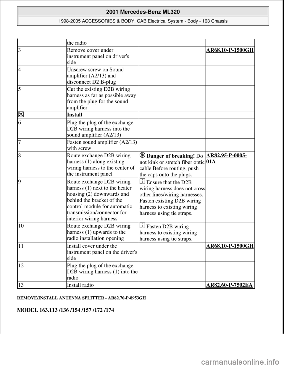
the radio
3Remove cover under
instrument panel on driver's
side AR68.10-P-1500GH
4Unscrew screw on Sound
amplifier (A2/13) and
disconnect D2 B-plug
5Cut the existing D2B wiring
harness as far as possible away
from the plug for the sound
amplifier
Install
6Plug the plug of the exchange
D2B wiring harness into the
sound amplifier (A2/13)
7Fasten sound amplifier (A2/13)
with screw
8Route exchange D2B wiring
harness (1) along existing
wiring harness to the center of
the instrument panel Danger of breaking! Do
not kink or stretch fiber optic
cable Before routing, push
the caps onto the plugs.AR82.95-P-0005-
01A
9Route exchange D2B wiring
harness (1) next to the heater
housing (2) downwards and
behind the bracket of the
control module for automatic
transmission/connector for
interior wiring harness Ensure that the D2B
wiring harness does not cross
other lines/wiring harnesses.
Fasten existing D2B wiring
harness to existing wiring
harness using tie straps.
10Route exchange D2B wiring
harness (1) upwards to the
radio installation opening Fasten D2B wiring
harness to existing wiring
harness using tie straps.
11Install cover under the
instrument panel on the driver's
side AR68.10-P-1500GH
12Plug the plug of the exchange
D2B wiring harness (1) into the
radio
13Install radio AR82.60-P-7502EA
2001 Mercedes-Benz ML320
1998-2005 ACCESSORIES & BODY, CAB Electrical System - Body - 163 Chassis
me
Saturday, October 02, 2010 3:30:10 PMPage 315 © 2006 Mitchell Repair Information Company, LLC.
Page 1814 of 4133
![MERCEDES-BENZ ML430 1997 Complete Repair Manual Front seats
REPLACE FIBER OPTICAL CABLE (D2B) BETWEEN THE RADIO AND E-CALL CONTROL MODULE/CTEL [TEL]
INTERFACE (AFTER TESTING) - AR82.95-P-0015GH
MODEL 163.136 #A as of 051500, 163.136 #X as of 70 MERCEDES-BENZ ML430 1997 Complete Repair Manual Front seats
REPLACE FIBER OPTICAL CABLE (D2B) BETWEEN THE RADIO AND E-CALL CONTROL MODULE/CTEL [TEL]
INTERFACE (AFTER TESTING) - AR82.95-P-0015GH
MODEL 163.136 #A as of 051500, 163.136 #X as of 70](/manual-img/4/57307/w960_57307-1813.png)
Front seats
REPLACE FIBER OPTICAL CABLE (D2B) BETWEEN THE RADIO AND E-CALL CONTROL MODULE/CTEL [TEL]
INTERFACE (AFTER TESTING) - AR82.95-P-0015GH
MODEL 163.136 #A as of 051500, 163.136 #X as of 708319, 163.154 #A as of 051500, 163.154 #X as of
708319, 163.172 #A as of 051500, 163.172 #X as of 708319, 163.113/128/157/174/175 with CODE (852)
CTEL preinstallation assembly at dome with CODE (854) MB portable cellular telephone
MODEL 163.154 /172 /174 #A as of 221506, 163.157/175 with CODE (349) E Call emergency call system
with CODE (494a) USA version
1Remove fuse f8 from fuse
and relay module
2Unscrew screws on front
seat console *BA91.10-P-1001-01B
3Angle front seat back
until it rests against the
rear bench seat and fasten
with outer seat belt Remove wiring
harness for E-call speaker
from E-call bracket.
Cover the floor covering
behind the front seat to
avoid contamination.
4Detach connector (2) and
antenna plug (4) from the
E-call control module
(A35/8)
5Detach conductive
coupling D2B (3) Do not kink or stretch
fiber optic cable. Press
protective caps on
conductive coupling and
device connection.AR82.95-P-0005-01A
6Unscrew screws (5)
7Remove E-call control
module (A35/8)
8Install in the reverse order
NumberDesignationModel Series 163
BA91.10-P-1001-01BBolt of seating mounting
bracket to vehicle floorNm40
2001 Mercedes-Benz ML320
1998-2005 ACCESSORIES & BODY, CAB Electrical System - Body - 163 Chassis
me
Saturday, October 02, 2010 3:30:10 PMPage 319 © 2006 Mitchell Repair Information Company, LLC.
Page 1815 of 4133

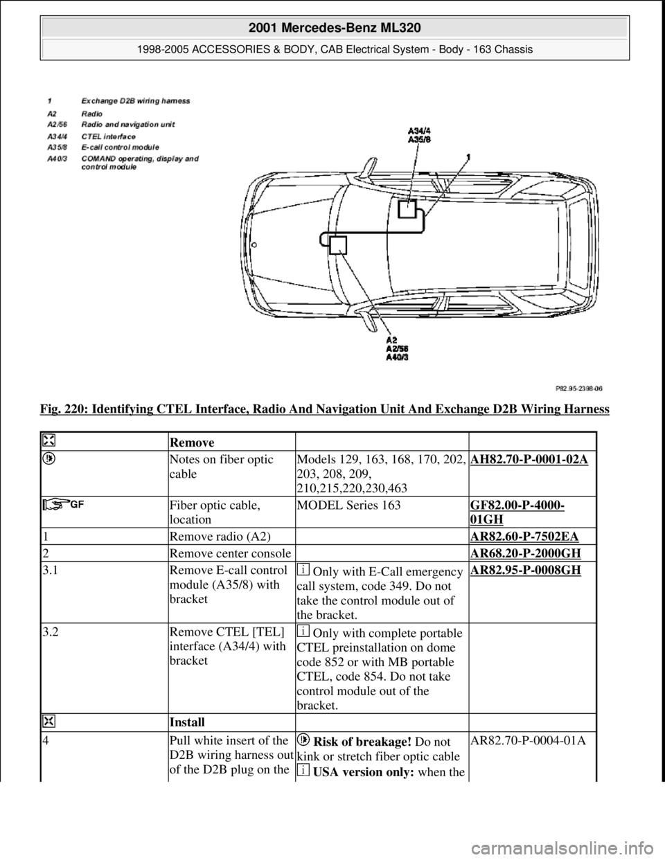
Fig. 220: Identifying CTEL Interface, Radio And Navigation Unit And Exchange D2B Wiring Harness
Remove
Notes on fiber optic
cableModels 129, 163, 168, 170, 202,
203, 208, 209,
210,215,220,230,463AH82.70-P-0001-02A
Fiber optic cable,
locationMODEL Series 163GF82.00-P-4000-
01GH
1Remove radio (A2) AR82.60-P-7502EA
2Remove center console AR68.20-P-2000GH
3.1Remove E-call control
module (A35/8) with
bracket Only with E-Call emergency
call system, code 349. Do not
take the control module out of
the bracket.AR82.95-P-0008GH
3.2Remove CTEL [TEL]
interface (A34/4) with
bracket Only with complete portable
CTEL preinstallation on dome
code 852 or with MB portable
CTEL, code 854. Do not take
control module out of the
bracket.
Install
4Pull white insert of the
D2B wiring harness out
of the D2B plug on the Risk of breakage! Do not
kink or stretch fiber optic cable
USA version only: when the AR82.70-P-0004-01A
2001 Mercedes-Benz ML320
1998-2005 ACCESSORIES & BODY, CAB Electrical System - Body - 163 Chassis
me
Saturday, October 02, 2010 3:30:10 PMPage 320 © 2006 Mitchell Repair Information Company, LLC.