1997 MERCEDES-BENZ ML430 tailgate
[x] Cancel search: tailgatePage 3209 of 4133
AR88.40-P-3000GH
Remove/install engine hood
25.3.97
MODEL
163.113 /128 /136 /154 /157 /172 /174 /175
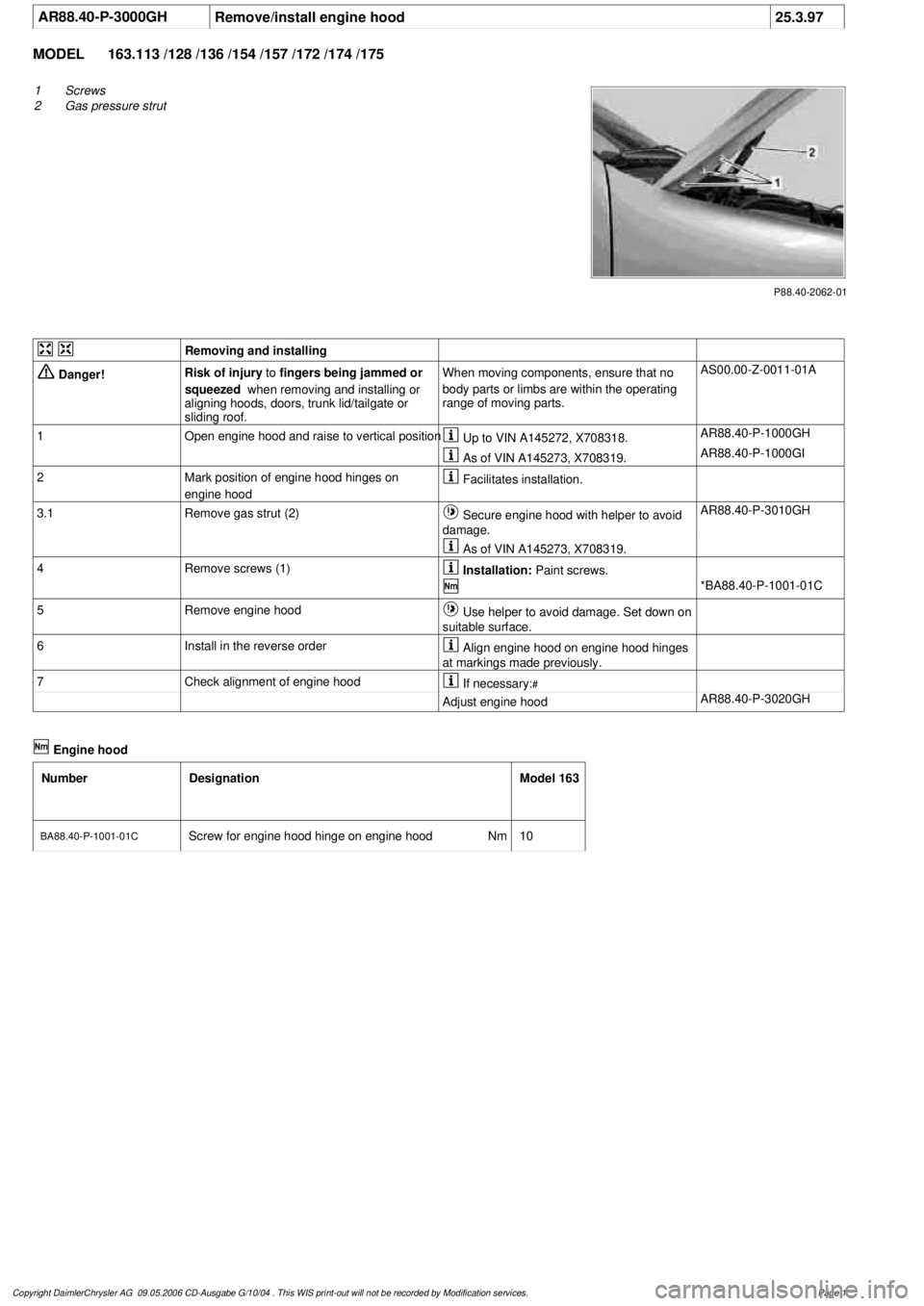
P88.40-2062-01
1
Screws
2
Gas pressure strut
Removing and installing
Danger!
Risk of injury
to
fingers being jammed or
squeezed
when removing and installing or
aligning hoods, doors, trunk lid/tailgate or
sliding roof.
When moving components, ensure that no
body parts or limbs are within the operating
range of moving parts.
AS00.00-Z-0011-01A
1
Open engine hood and raise to vertical position
Up to VIN A145272, X708318.
AR88.40-P-1000GH
As of VIN A145273, X708319.
AR88.40-P-1000GI
2
Mark position of engine hood hinges on
engine hood
Facilitates installation.
3.1
Remove gas strut (2)
Secure engine hood with helper to avoid
damage.
AR88.40-P-3010GH
As of VIN A145273, X708319.
4
Remove screws (1)
Installation:
Paint screws.
*BA88.40-P-1001-01C
5
Remove engine hood
Use helper to avoid damage. Set down on
suitable surface.
6
Install in the reverse order
Align engine hood on engine hood hinges
at markings made previously.
7
Check alignment of engine hood
If necessary:
#
Adjust engine hood
AR88.40-P-3020GH
Engine hood
Number
Designation
Model 163
BA88.40-P-1001-01C
Screw for engine hood hinge on engine hood
Nm
10
Copyright DaimlerChrysler AG 09.05.2006 CD-Ausgabe G/10/04 . This WIS print-out will not be recorde
d by Modification services.
Page 1
Page 3584 of 4133
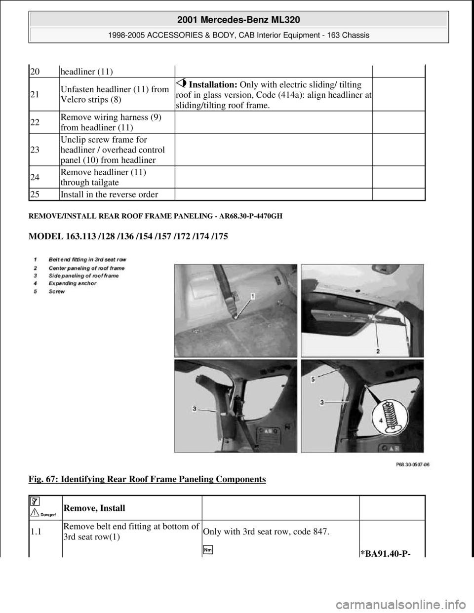
REMOVE/INSTALL REAR ROOF FRAME PANELING - AR68.30-P-4470GH
MODEL 163.113 /128 /136 /154 /157 /172 /174 /175
Fig. 67: Identifying Rear Roof Frame Paneling Components
20headliner (11)
21Unfasten headliner (11) from
Velcro strips (8) Installation: Only with electric sliding/ tilting
roof in glass version, Code (414a): align headliner at
sliding/tilting roof frame.
22Remove wiring harness (9)
from headliner (11)
23
Unclip screw frame for
headliner / overhead control
panel (10) from headliner
24Remove headliner (11)
through tailgate
25Install in the reverse order
Remove, Install
1.1Remove belt end fitting at bottom of
3rd seat row(1)Only with 3rd seat row, code 847.
*BA91.40-P-
2001 Mercedes-Benz ML320
1998-2005 ACCESSORIES & BODY, CAB Interior Equipment - 163 Chassis
me
Saturday, October 02, 2010 3:35:22 PMPage 66 © 2006 Mitchell Repair Information Company, LLC.
Page 3752 of 4133
AR46.20-P-0600GH
Removing and installing rack-and-pinion steering
1.3.97
MODEL
163.113 /128 /136 /154 /157 /172 /174 /175
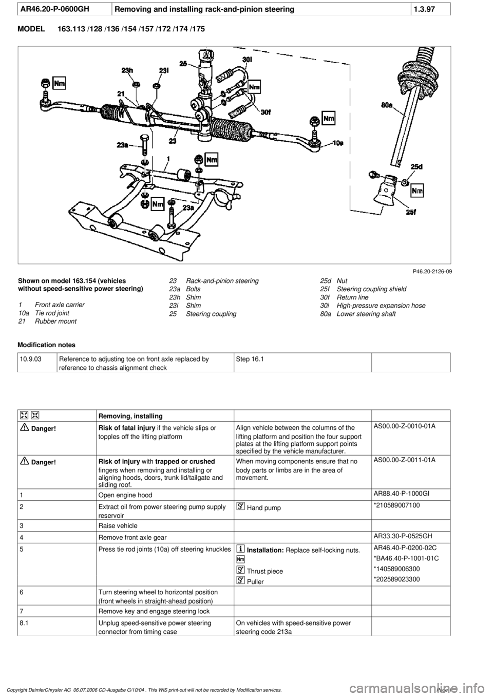
P46.20-2126-09
Shown on model 163.154 (vehicles
without speed-sensitive power steering)
1
Front axle carrier
10a
Tie rod joint
21
Rubber mount
25d
Nut
25f
Steering coupling shield
30f
Return line
30i
High-pressure expansion hose
80a
Lower steering shaft
23
Rack-and-pinion steering
23a
Bolts
23h
Shim
23i
Shim
25
Steering coupling
Modification notes
10.9.03
Reference to adjusting toe on front axle replaced by
reference to chassis alignment check
Step 16.1
Removing, installing
Danger!
Risk of fatal injury
if the vehicle slips or
topples off the lifting platform
Align vehicle between the columns of the
lifting platform and position the four support
plates
at the lifting platform support points
specified by the vehicle manufacturer.
AS00.00-Z-0010-01A
Danger!
Risk of injury
with
trapped or crushed
fingers when removing and installing or
aligning hoods, doors, trunk lid/tailgate and
sliding roof.
When moving components ensure that no
body parts or limbs are in the area of
movement.
AS00.00-Z-0011-01A
1
Open engine hood
AR88.40-P-1000GI
2
Extract oil from power steering pump supply
reservoir
Hand pump
*210589007100
3
Raise vehicle
4
Remove front axle gear
AR33.30-P-0525GH
5
Press tie rod joints (10a) off steering knuckles
Installation:
Replace self-locking nuts.
AR46.40-P-0200-02C
*BA46.40-P-1001-01C
Thrust piece
*140589006300
Puller
*202589023300
6
Turn steering wheel to horizontal position
(front wheels in straight-ahead position)
7
Remove key and engage steering lock
8.1
Unplug speed-sensitive power steering
connector from timing case
On vehicles with speed-sensitive power
steering code 213a
Copyright DaimlerChrysler AG 06.07.2006 CD-Ausgabe G/10/04 . This WIS print-out will not be recorde
d by Modification services.
Page 1
Page 3759 of 4133
AR20.40-P-5000M
Remove/install electric fan
24.8.99
ENGINE
612.963 in MODEL 163.113
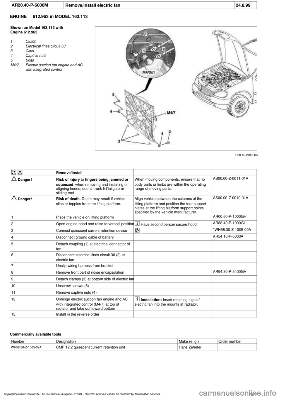
P20.40-2015-06
Shown on Model 163.113 with
Engine 612.963
1
Clutch
2
Electrical lines circuit 30
3
Clips
4
Captive nuts
5
Bolts
M4/7
Electric suction fan engine and AC
with integrated control
Remove/Install
Danger!
Risk of injury
to
fingers being jammed or
squeezed
when removing and installing or
aligning hoods, doors, trunk lid/tailgate or
sliding roof.
When moving components, ensure that no
body parts or limbs are within the operating
range of moving parts.
AS00.00-Z-0011-01A
Danger!
Risk of death.
Death may result if vehicle
slips or topples from the lifting platform.
Align vehicle between the columns of the
lifting platform and position the four support
plates
at the lifting platform support points
specified by the vehicle manufacturer.
AS00.00-Z-0010-01A
1
Place the vehicle on lifting platform
AR00.60-P-1000GH
2
Open engine hood and raise to vertical position
Have second person secure hood.
AR88.40-P-1000GI
3
Connect quiescent current retention device
*WH58.30-Z-1005-09A
4
Disconnect ground cable of battery
AR54.10-P-0003A
5
Detach coupling (1) at electrical connector of
fan
6
Disconnect electrical lines circuit 30 (2) at
electric fan
7
Unclip wiring harness from bracket
8
Remove front part of noise encapsulation
AR94.30-P-5400GH
9
Detach clamps (3) at bottom side of electric fan
10
Unscrew screws (5)
11
Remove captive nuts (4)
12
Unhinge electric suction fan engine and AC
with integrated control (M4/7) at top of
radiator and take out toward bottom
Installation:
Insert retaining lugs of
electric fan into the mounts at radiator.
13
Install in the reverse order
Commercially available tools
Number
Designation
Make (e. g.)
Order number
WH58.30-Z-1005-09A
CMP 12.2 quiescent current retention unit
Hans Zeheter
Copyright DaimlerChrysler AG 12.05.2006 CD-Ausgabe G/10/04 . This WIS print-out will not be recorde
d by Modification services.
Page 1
Page 3760 of 4133
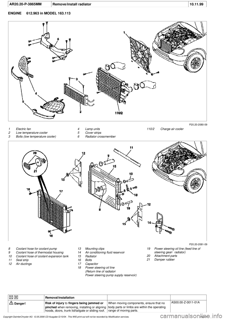
AR20.20-P-3865MM
Remove/install radiator
10.11.99
ENGINE
612.963 in MODEL 163.113
P20.20-2080-09
1
Electric fan
2
Low temperature cooler
3
Bolts (low temperature cooler)
110/2
Charge air cooler
4
Lamp units
5
Cover strips
6
Radiator crossmember
P20.20-2081-09
8
Coolant hose for coolant pump
9
Coolant hose of thermostat housing
10
Coolant hose of coolant expansion tank
11
Seal strip
12
Air ductings
19
Power steering oil line (feed line of
steering gear
!
radiator)
20
Attachment parts
21
Damper rubber
13
Mounting clips
14
Air conditioning fluid reservoir
15
Radiator
16
Bolts
17
Capacitor
18
Power steering oil line
(Return line of radiator
!
Power steering pump supply reservoir)
Removal/installation
Danger!
Risk of injury
to
fingers being jammed or
pinched
when removing, installing or aligning
hoods, doors, trunk lid/tailgate or sliding roof.
When moving components, ensure that no
body parts or limbs are within the operating
range of moving parts.
AS00.00-Z-0011-01A
Copyright DaimlerChrysler AG 12.05.2006 CD-Ausgabe G/10/04 . This WIS print-out will not be recorde
d by Modification services.
Page 1
Page 3771 of 4133
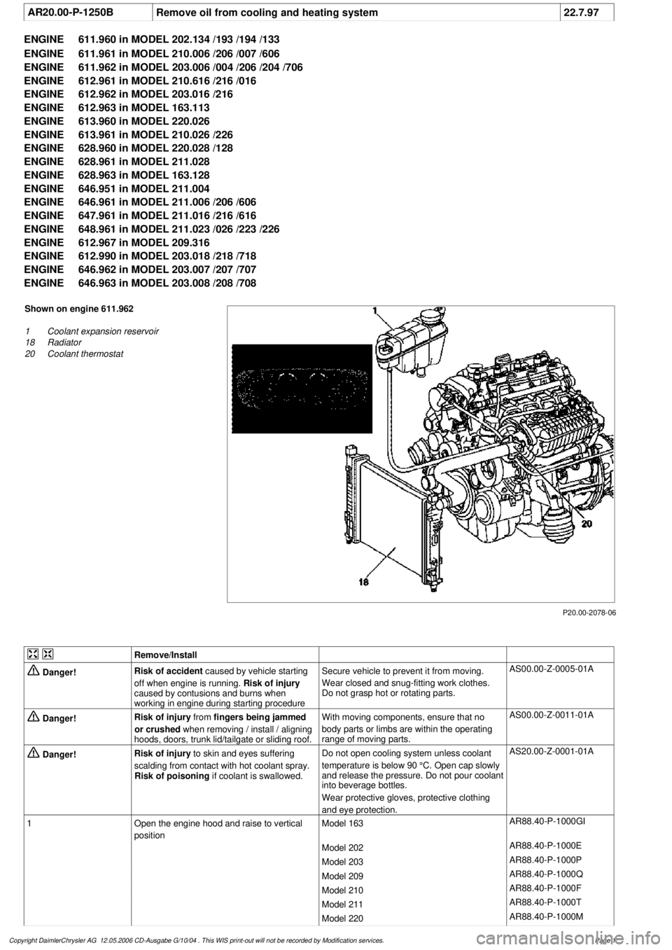
AR20.00-P-1250B
Remove oil from cooling and heating system
22.7.97
ENGINE
611.960 in MODEL 202.134 /193 /194 /133
ENGINE
611.961 in MODEL 210.006 /206 /007 /606
ENGINE
611.962 in MODEL 203.006 /004 /206 /204 /706
ENGINE
612.961 in MODEL 210.616 /216 /016
ENGINE
612.962 in MODEL 203.016 /216
ENGINE
612.963 in MODEL 163.113
ENGINE
613.960 in MODEL 220.026
ENGINE
613.961 in MODEL 210.026 /226
ENGINE
628.960 in MODEL 220.028 /128
ENGINE
628.961 in MODEL 211.028
ENGINE
628.963 in MODEL 163.128
ENGINE
646.951 in MODEL 211.004
ENGINE
646.961 in MODEL 211.006 /206 /606
ENGINE
647.961 in MODEL 211.016 /216 /616
ENGINE
648.961 in MODEL 211.023 /026 /223 /226
ENGINE
612.967 in MODEL 209.316
ENGINE
612.990 in MODEL 203.018 /218 /718
ENGINE
646.962 in MODEL 203.007 /207 /707
ENGINE
646.963 in MODEL 203.008 /208 /708
P20.00-2078-06
Shown on engine 611.962
1
Coolant expansion reservoir
18
Radiator
20
Coolant thermostat
Remove/Install
Danger!
Risk of accident
caused by vehicle starting
off when engine is running.
Risk of injury
caused by contusions and burns when
working in engine during starting procedure
Secure vehicle to prevent it from moving.
Wear closed and snug-fitting work clothes.
Do not grasp hot or rotating parts.
AS00.00-Z-0005-01A
Danger!
Risk of injury
from
fingers being jammed
or crushed
when removing / install / aligning
hoods, doors, trunk lid/tailgate or sliding roof.
With moving components, ensure that no
body parts or limbs are within the operating
range of moving parts.
AS00.00-Z-0011-01A
Danger!
Risk of injury
to skin and eyes suffering
scalding from contact with hot coolant spray.
Risk of poisoning
if coolant is swallowed.
Do not open cooling system unless coolant
temperature is below 90 °C. Open cap slowly
and release the pressure. Do not pour coolant
into beverage bottles.
Wear protective gloves, protective clothing
and eye protection.
AS20.00-Z-0001-01A
1
Open the engine hood and raise to vertical
position
Model 163
AR88.40-P-1000GI
Model 202
AR88.40-P-1000E
Model 203
AR88.40-P-1000P
Model 209
AR88.40-P-1000Q
Model 210
AR88.40-P-1000F
Model 211
AR88.40-P-1000T
Model 220
AR88.40-P-1000M
Copyright DaimlerChrysler AG 12.05.2006 CD-Ausgabe G/10/04 . This WIS print-out will not be recorde
d by Modification services.
Page 1
Page 3810 of 4133
13
Unhook vertical adjustment cable (6) from
vertical adjustment handle (5)
14
Guide vertical adjustment cable (6) through
grommet (12)
Installation:
If a new rear seat cushion
frame is used, the grommet must be installed
in the new rear seat cushion frame.
15
Remove handle locking device (13) from rear
seat cushion frame
16
Unhook horizontal adjustment cable (8) at clip
(10) and at front of rear seat cushion frame
Risk of breakage!
17
Unscrew bolts from horizontal adjustment
handle
18
Detach horizontal adjustment cable (8) from
horizontal adjustment handle
Risk of breakage!
Pull out horizontal adjustment handle.
19
Remove rear seat seat belt buckle
40% rear seat without side airbag in left
and right rear, code 293.
AR91.40-P-1516GH
40% rear seat with side airbag in left and
right rear, code 293.
AR91.40-P-1516GK
60% rear seat outer seat.
AR91.40-P-1516GJ
20
Unscrew mounting screws for rear seat
cushion frame (2)
Installation:
Replace damaged shims at
the diagonal supports of the rear seat.
*BA91.12-P-1010-03A
21
Remove rear seat cushion frame (3)
Remove rear seat cushion frame through
tailgate
22
Install in the reverse order
Rear seats
Number
Designation
Model
163 as of
09/99
BA91.12-P-1009-03A
Bolt for clamping band to seat frame
Nm
45
BA91.12-P-1010-03A
Screw for bracket to seat frame
Nm
23
Torx bit set
000 589 01 10 00
Copyright DaimlerChrysler AG 14.06.2006 CD-Ausgabe G/10/04 . This WIS print-out will not be recorde
d by Modification services.
Page 2
Page 3904 of 4133
AR88.30-P-0200-04GH
Prepare cutting tool
Commercially available tools
(see Workshop Equipment Manual)
Number
Designation
Make (e. g.)
Order number
WH58.30-Z-1010-10A
Cutting tool kit (compressed-air tool + blades)
Europe:
The Barn
Holly Tree Farm
Holmes Chapel Road
Lower Withington,
Cheshire, SK11 9DT
England
Tel.:
+44 1477 571700
Japan:
Osaka Chamber of
Commerce
2-8 Hommachibashi
Chuo-ku
Osaka, Japan, 540-
0029
Tel.:+81 6 6944 6445
USA:
SPX
Dealer Equipment
Services Tel.:
+1-888-458-4040
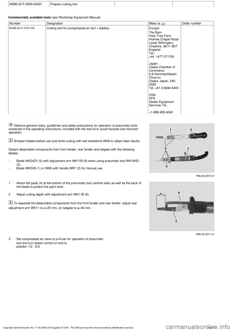
P88.30-2070-01
Observe general notes, guidelines and safety precautions for operation of pneumatic tools
contained in the operating instructions, included with the tool kit to avoid hazards and incorrect
operation.
Sharpen blades before use and while cutting with wet whetstone WK8 to obtain best results.
Detach detachable components from front fender, rear fender and tailgate with the following
blades:
-
Blade WK24ZV (5) with adjustment arm WK11B (6) when using pneumatic tool WK10HD
(3).
-
Blade WK24S (1) or WK6 with handle WK7 (2) for manual use.
P88.30-2071-01
1
Attach felt pads (4) at the bottom of the pneumatic tool (vehicle side) as well as the back of
the blade to protect the paint work.
2
Adjust cutting depth with adjustment arm WK11B (6).
To separate the detachable components from the front fender and rear fender, adjust rear
adjustment arm WK11 to a=25 mm, on tailgate to a=40 mm.
3
Set compressed air valve to p=6 bar for operation of pneumatic
tool and turn power control on tool to
position 1/2 - 2/3.
Copyright DaimlerChrysler AG 17.05.2006 CD-Ausgabe G/10/04 . This WIS print-out will not be recorde
d by Modification services.
Page 1