Page 1776 of 4133
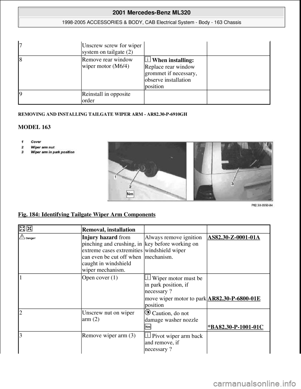
REMOVING AND INSTALLING TAILGATE WIPER ARM - AR82.30-P-6910GH
MODEL 163
Fig. 184: Identifying Tailgate Wiper Arm Components
7Unscrew screw for wiper
system on tailgate (2)
8Remove rear window
wiper motor (M6/4) When installing:
Replace rear window
grommet if necessary,
observe installation
position
9Reinstall in opposite
order
Removal, installation
Injury hazard from
pinching and crushing, in
extreme cases extremities
can even be cut off when
caught in windshield
wiper mechanism.Always remove ignition
key before working on
windshield wiper
mechanism.AS82.30-Z-0001-01A
1Open cover (1) Wiper motor must be
in park position, if
necessary ?
move wiper motor to park
positionAR82.30-P-6800-01E
2Unscrew nut on wiper
arm (2) Caution, do not
damage washer nozzle
*BA82.30-P-1001-01C
3Remove wiper arm (3) Pivot wiper arm back
and remove, if
necessary ?
2001 Mercedes-Benz ML320
1998-2005 ACCESSORIES & BODY, CAB Electrical System - Body - 163 Chassis
me
Saturday, October 02, 2010 3:30:09 PMPage 281 © 2006 Mitchell Repair Information Company, LLC.
Page 1795 of 4133
REMOVE, INSTALL AM/FM AMPLIFIER - AR82.62-P-8347GH
MODEL 163
Fig. 202: Identifying AM/FM Amplifier Components
housing (3)
4Unscrew screws (4) and
remove loudspeaker
(H4/3, H4/4)
5Reinstall in opposite
order
6Check for proper function Switch on radio,
actuate balance control,
check left and right
loudspeakers
Remove/install
1Open tailgate
2Remove liner on tailgate AR72.20-P-3520GH
3Disconnect electrical
connectors (2, 3, 4)
4Unscrew screws (1)
5Remove AM/FM
2001 Mercedes-Benz ML320
1998-2005 ACCESSORIES & BODY, CAB Electrical System - Body - 163 Chassis
me
Saturday, October 02, 2010 3:30:10 PMPage 300 © 2006 Mitchell Repair Information Company, LLC.
Page 1799 of 4133
Fig. 205: Identifying CD Player Components
Fig. 206: Identifying CD Player Components
Remove/Install
1Open tailgate
2Open cover (1) and
remove
3Loosen butterfly screw (2)
for mount (3)
4Remove bolts (4).
5Pull CD player with
changer (in trunk) (A2/6)
forward
6Disconnect electrical plug
(8)
7Remove CD player with
changer Installation: Ensure
that the vertical
installation position is set
on the side of the CD
player.
8Unhook electric lead (5)
from retaining clips (6)
9Unscrew screws (7) and
remove CD player with
changer from mount
10Install in the reverse order
11Perform a function test
2001 Mercedes-Benz ML320
1998-2005 ACCESSORIES & BODY, CAB Electrical System - Body - 163 Chassis
me
Saturday, October 02, 2010 3:30:10 PMPage 304 © 2006 Mitchell Repair Information Company, LLC.
Page 1811 of 4133
Fig. 216: Identifying Antenna Splitter Components
REMOVE/INSTALL ELECTRONIC COMPASS - AR82.85-P-7371GH
MODELS 163.113 /154 /172 /174 #A as of 221506, 163.113 #X as of 734088, 163.128 /157 /175 with CODE
(245) Trip computer
Remove/install
Information on preventing
damage to electronic
components due to
electrostatic discharge AH54.00-P-0001-01A
1Open rear-end door
2Remove liner on tailgate AR72.20-P-3520GH
3Remove bolts (1, 2)
4Disconnect electrical
connectors (3)
5Remove radio antenna
splitter (A2/5)
6Install in the reverse order
2001 Mercedes-Benz ML320
1998-2005 ACCESSORIES & BODY, CAB Electrical System - Body - 163 Chassis
me
Saturday, October 02, 2010 3:30:10 PMPage 316 © 2006 Mitchell Repair Information Company, LLC.
Page 1972 of 4133
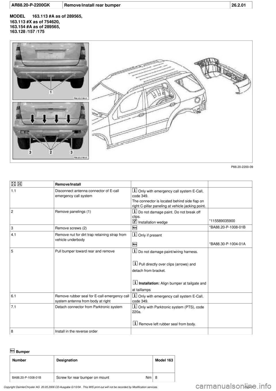
AR88.20-P-2200GK
Remove/install rear bumper
26.2.01
MODEL
163.113 #A as of 289565,
163.113 #X as of 754620,
163.154 #A as of 289565,
163.128 /157 /175
P88.20-2200-09
Remove/Install
1.1
Disconnect antenna connector of E-call
emergency call system
Only with emergency call system E-Call,
code 349.
The connector is located behind side flap on
right C-pillar paneling at vehicle jacking point.
2
Remove panelings (1)
Do not damage paint. Do not break off
clips.
Installation wedge
*115589035900
3
Remove screws (2)
*BA88.20-P-1008-01B
4.1
Remove nut for dirt trap retaining strap from
vehicle underbody
Only if present
*BA88.30-P-1004-01A
5
Pull bumper toward rear and remove
Do not damage paint/wiring harness.
Pull directly over clips (arrows) and
detach from bracket.
Installation:
Align bumper at tailgate and
at taillamps
6.1
Remove rubber seal for E-call emergency call
system antenna from body at right
Only with emergency call system E-Call,
code 349.
7.1
Detach connector from Parktronic system
Only with Parktronic system (PTS), code
220a.
Remove left rubber seal from body.
8
Install in the reverse order
Bumper
Number
Designation
Model 163
BA88.20-P-1008-01B
Screw for rear bumper on mount
Nm
8
Copyright DaimlerChrysler AG 20.05.2006 CD-Ausgabe G/10/04 . This WIS print-out will not be recorde
d by Modification services.
Page 1
Page 1982 of 4133
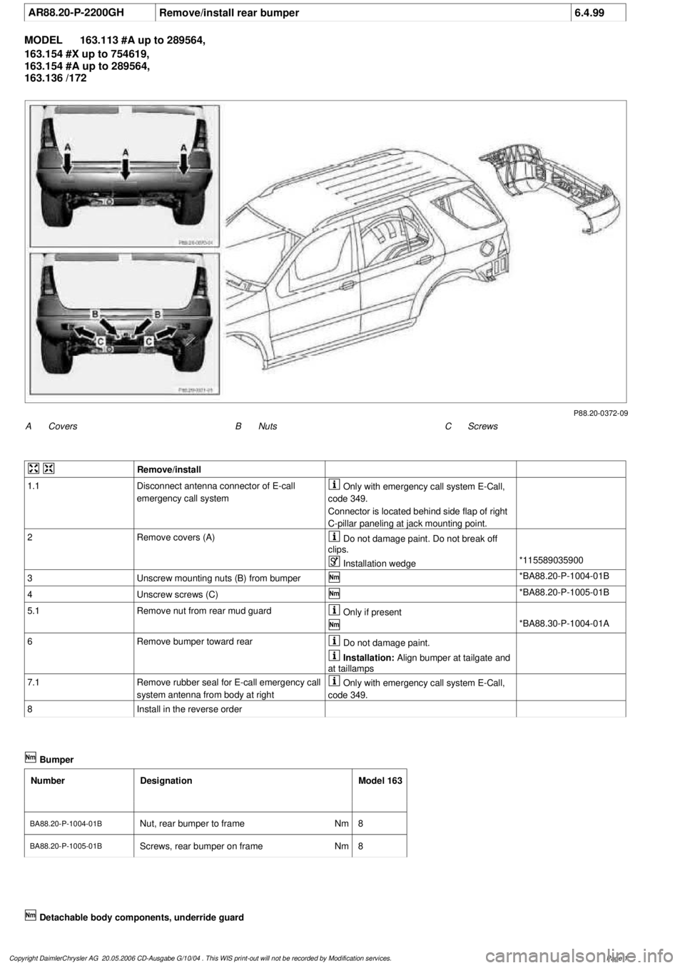
AR88.20-P-2200GH
Remove/install rear bumper
6.4.99
MODEL
163.113 #A up to 289564,
163.154 #X up to 754619,
163.154 #A up to 289564,
163.136 /172
P88.20-0372-09
A
Covers
C
Screws
B
Nuts
Remove/install
1.1
Disconnect antenna connector of E-call
emergency call system
Only with emergency call system E-Call,
code 349.
Connector is located behind side flap of right
C-pillar paneling at jack mounting point.
2
Remove covers (A)
Do not damage paint. Do not break off
clips.
Installation wedge
*115589035900
3
Unscrew mounting nuts (B) from bumper
*BA88.20-P-1004-01B
4
Unscrew screws (C)
*BA88.20-P-1005-01B
5.1
Remove nut from rear mud guard
Only if present
*BA88.30-P-1004-01A
6
Remove bumper toward rear
Do not damage paint.
Installation:
Align bumper at tailgate and
at taillamps
7.1
Remove rubber seal for E-call emergency call
system antenna from body at right
Only with emergency call system E-Call,
code 349.
8
Install in the reverse order
Bumper
Number
Designation
Model 163
BA88.20-P-1004-01B
Nut, rear bumper to frame
Nm
8
BA88.20-P-1005-01BScrews, rear bumper on frame
Nm
8
Copyright DaimlerChrysler AG 20.05.2006 CD-Ausgabe G/10/04 . This WIS print-out will not be recorde
d by Modification services.
Page 1
Page 1984 of 4133
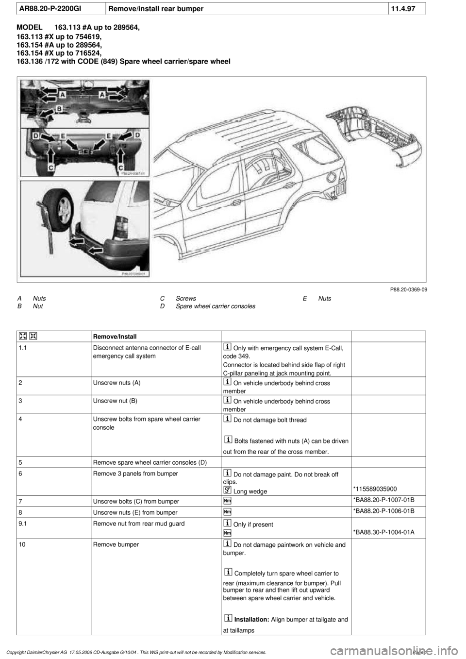
AR88.20-P-2200GI
Remove/install rear bumper
11.4.97
MODEL
163.113 #A up to 289564,
163.113 #X up to 754619,
163.154 #A up to 289564,
163.154 #X up to 716524,
163.136 /172 with CODE (849) Spare wheel carrier/spare wheel
P88.20-0369-09
A
Nuts
B
Nut
E
Nuts
C
Screws
D
Spare wheel carrier consoles
Remove/Install
1.1
Disconnect antenna connector of E-call
emergency call system
Only with emergency call system E-Call,
code 349.
Connector is located behind side flap of right
C-pillar paneling at jack mounting point.
2
Unscrew nuts (A)
On vehicle underbody behind cross
member
3
Unscrew nut (B)
On vehicle underbody behind cross
member
4
Unscrew bolts from spare wheel carrier
console
Do not damage bolt thread
Bolts fastened with nuts (A) can be driven
out from the rear of the cross member.
5
Remove spare wheel carrier consoles (D)
6
Remove 3 panels from bumper
Do not damage paint. Do not break off
clips.
Long wedge
*115589035900
7
Unscrew bolts (C) from bumper
*BA88.20-P-1007-01B
8
Unscrew nuts (E) from bumper
*BA88.20-P-1006-01B
9.1
Remove nut from rear mud guard
Only if present
*BA88.30-P-1004-01A
10
Remove bumper
Do not damage paintwork on vehicle and
bumper.
Completely turn spare wheel carrier to
rear (maximum clearance for bumper). Pull
bumper to rear and then lift out upward
between spare wheel carrier and vehicle.
Installation:
Align bumper at tailgate and
at taillamps
Copyright DaimlerChrysler AG 17.05.2006 CD-Ausgabe G/10/04 . This WIS print-out will not be recorde
d by Modification services.
Page 1
Page 1992 of 4133
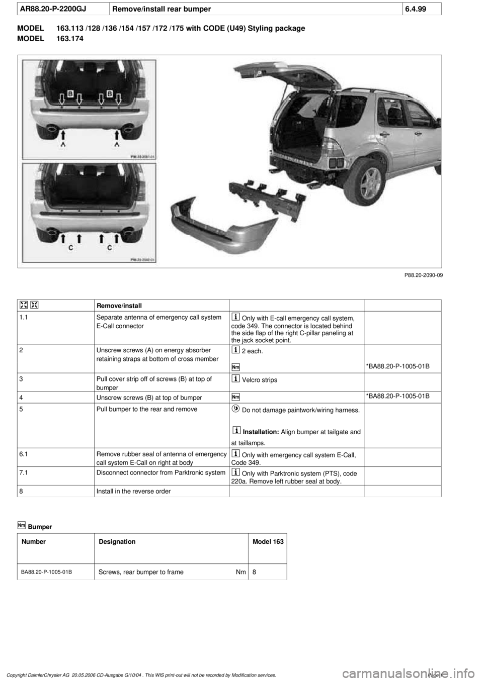
AR88.20-P-2200GJ
Remove/install rear bumper
6.4.99
MODEL
163.113 /128 /136 /154 /157 /172 /175 with CODE (U49) Styling package
MODEL
163.174
P88.20-2090-09
Remove/install
1.1
Separate antenna of emergency call system
E-Call connector
Only with E-call emergency call system,
code 349. The connector is located behind
the side flap of the right C-pillar paneling at
the jack socket point.
2
Unscrew screws (A) on energy absorber
retaining straps at bottom of cross member
2 each.
*BA88.20-P-1005-01B
3
Pull cover strip off of screws (B) at top of
bumper
Velcro strips
4
Unscrew screws (B) at top of bumper
*BA88.20-P-1005-01B
5
Pull bumper to the rear and remove
Do not damage paintwork/wiring harness.
Installation:
Align bumper at tailgate and
at taillamps.
6.1
Remove rubber seal of antenna of emergency
call system E-Call on right at body
Only with emergency call system E-Call,
Code 349.
7.1
Disconnect connector from Parktronic system
Only with Parktronic system (PTS), code
220a. Remove left rubber seal at body.
8
Install in the reverse order
Bumper
Number
Designation
Model 163
BA88.20-P-1005-01B
Screws, rear bumper to frame
Nm
8
Copyright DaimlerChrysler AG 20.05.2006 CD-Ausgabe G/10/04 . This WIS print-out will not be recorde
d by Modification services.
Page 1