Page 1993 of 4133
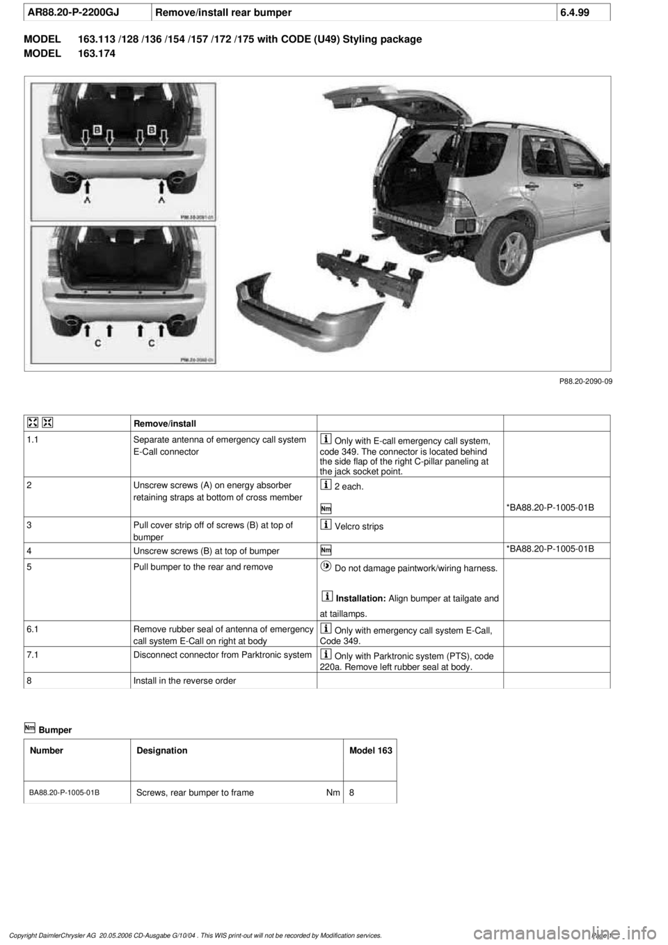
AR88.20-P-2200GJ
Remove/install rear bumper
6.4.99
MODEL
163.113 /128 /136 /154 /157 /172 /175 with CODE (U49) Styling package
MODEL
163.174
P88.20-2090-09
Remove/install
1.1
Separate antenna of emergency call system
E-Call connector
Only with E-call emergency call system,
code 349. The connector is located behind
the side flap of the right C-pillar paneling at
the jack socket point.
2
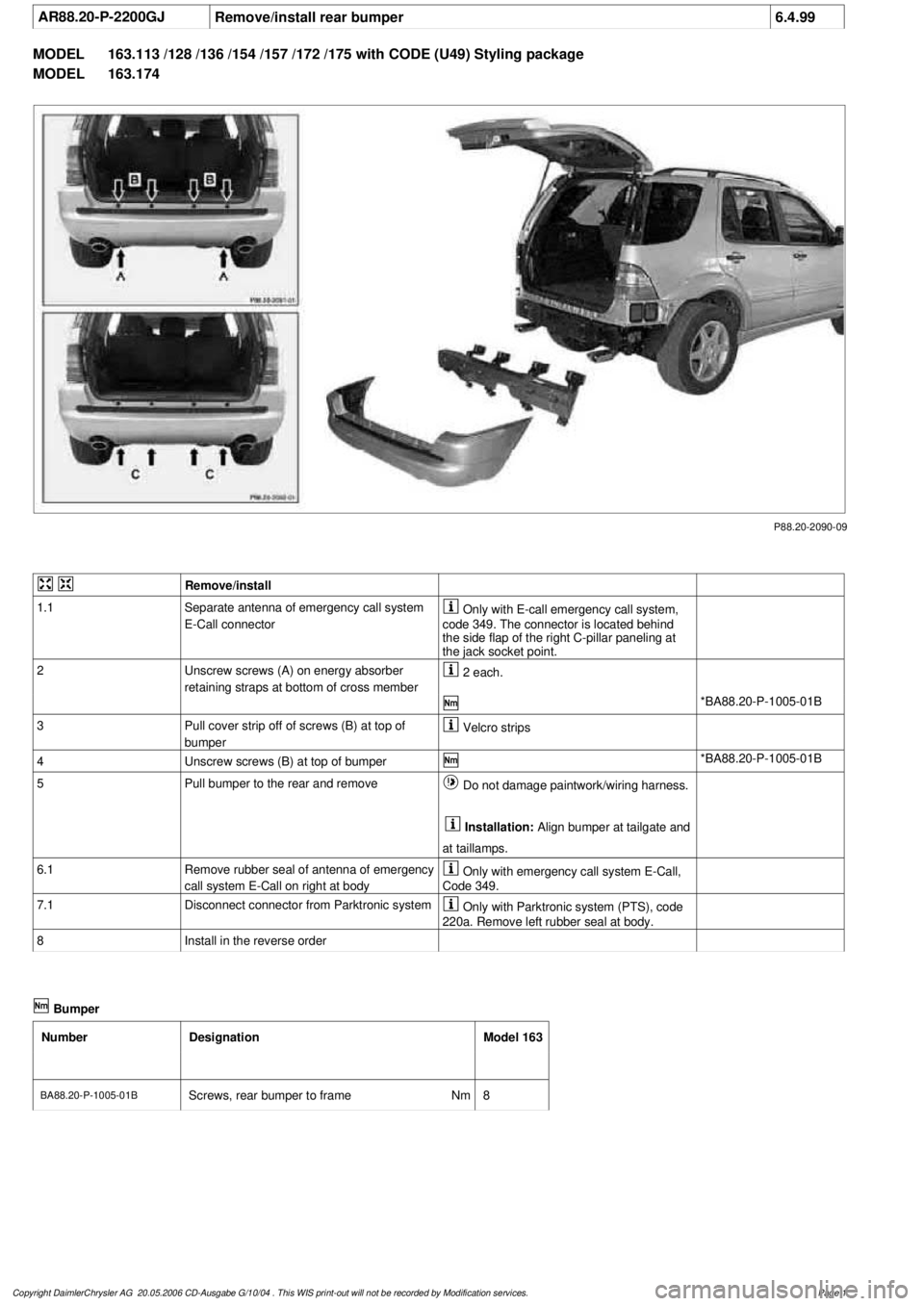
Unscrew screws (A) on energy absorber
retaining straps at bottom of cross member
2 each.
*BA88.20-P-1005-01B
3
Pull cover strip off of screws (B) at top of
bumper
Velcro strips
4
Unscrew screws (B) at top of bumper
*BA88.20-P-1005-01B
5
Pull bumper to the rear and remove
Do not damage paintwork/wiring harness.
Installation:
Align bumper at tailgate and
at taillamps.
6.1
Remove rubber seal of antenna of emergency
call system E-Call on right at body
Only with emergency call system E-Call,
Code 349.
7.1
Disconnect connector from Parktronic system
Only with Parktronic system (PTS), code
220a. Remove left rubber seal at body.
8
Install in the reverse order
Bumper
Number
Designation
Model 163
BA88.20-P-1005-01B
Screws, rear bumper to frame
Nm
8
Copyright DaimlerChrysler AG 20.05.2006 CD-Ausgabe G/10/04 . This WIS print-out will not be recorde
d by Modification services.
Page 1
Page 1998 of 4133
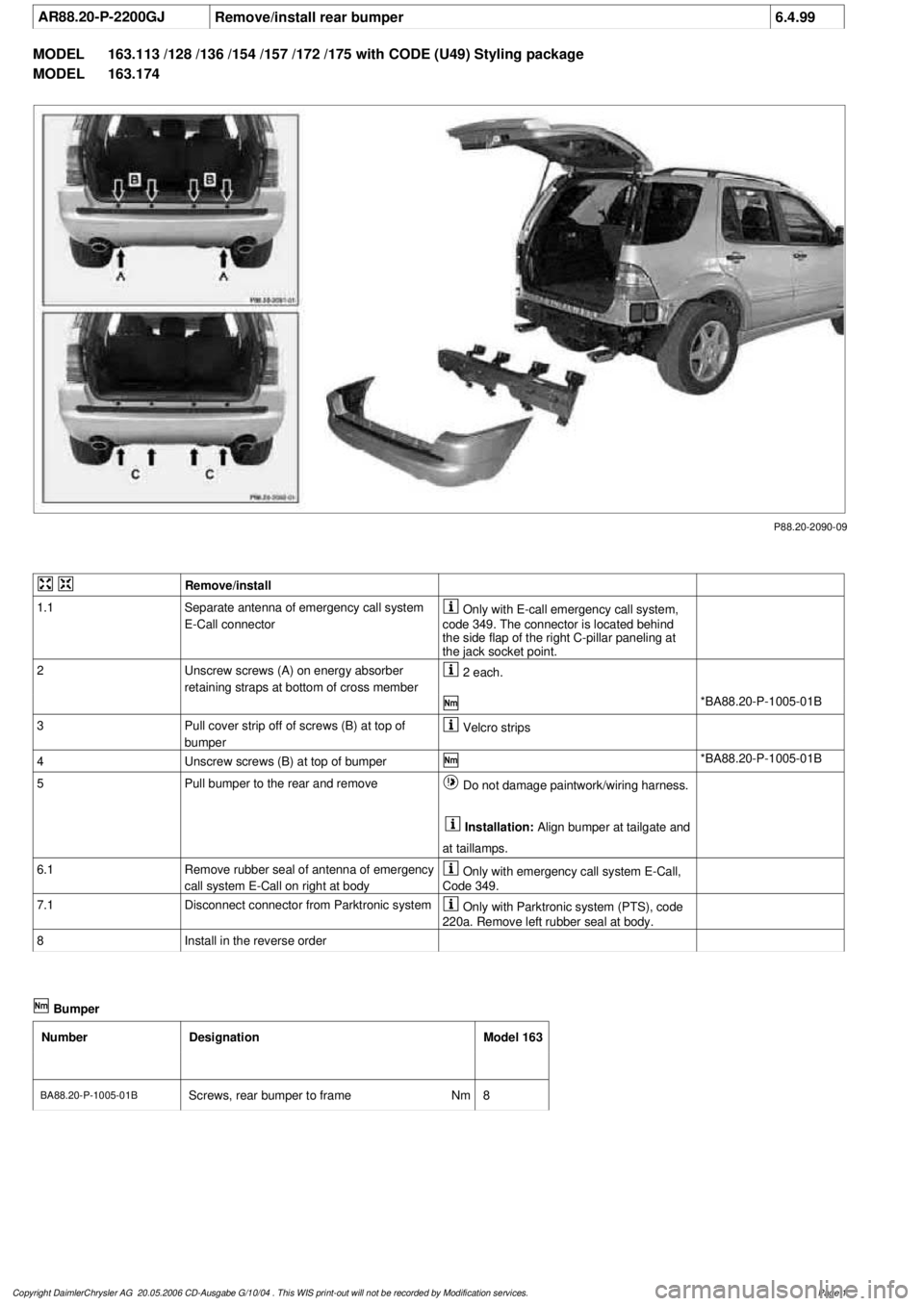
AR88.20-P-2200GJ
Remove/install rear bumper
6.4.99
MODEL
163.113 /128 /136 /154 /157 /172 /175 with CODE (U49) Styling package
MODEL
163.174
P88.20-2090-09
Remove/install
1.1
Separate antenna of emergency call system
E-Call connector
Only with E-call emergency call system,
code 349. The connector is located behind
the side flap of the right C-pillar paneling at
the jack socket point.
2
Unscrew screws (A) on energy absorber
retaining straps at bottom of cross member
2 each.
*BA88.20-P-1005-01B
3
Pull cover strip off of screws (B) at top of
bumper
Velcro strips
4
Unscrew screws (B) at top of bumper
*BA88.20-P-1005-01B
5
Pull bumper to the rear and remove
Do not damage paintwork/wiring harness.
Installation:
Align bumper at tailgate and
at taillamps.
6.1
Remove rubber seal of antenna of emergency
call system E-Call on right at body
Only with emergency call system E-Call,
Code 349.
7.1
Disconnect connector from Parktronic system
Only with Parktronic system (PTS), code
220a. Remove left rubber seal at body.
8
Install in the reverse order
Bumper
Number
Designation
Model 163
BA88.20-P-1005-01B
Screws, rear bumper to frame
Nm
8
Copyright DaimlerChrysler AG 20.05.2006 CD-Ausgabe G/10/04 . This WIS print-out will not be recorde
d by Modification services.
Page 1
Page 1999 of 4133
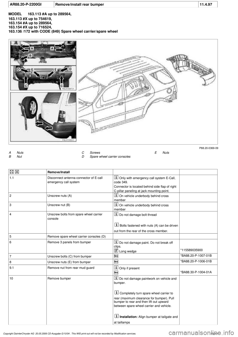
AR88.20-P-2200GI
Remove/install rear bumper
11.4.97
MODEL
163.113 #A up to 289564,
163.113 #X up to 754619,
163.154 #A up to 289564,
163.154 #X up to 716524,
163.136 /172 with CODE (849) Spare wheel carrier/spare wheel
P88.20-0369-09
A
Nuts
B
Nut
E
Nuts
C
Screws
D
Spare wheel carrier consoles
Remove/Install
1.1
Disconnect antenna connector of E-call
emergency call system
Only with emergency call system E-Call,
code 349.
Connector is located behind side flap of right
C-pillar paneling at jack mounting point.
2
Unscrew nuts (A)
On vehicle underbody behind cross
member
3
Unscrew nut (B)
On vehicle underbody behind cross
member
4
Unscrew bolts from spare wheel carrier
console
Do not damage bolt thread
Bolts fastened with nuts (A) can be driven
out from the rear of the cross member.
5
Remove spare wheel carrier consoles (D)
6
Remove 3 panels from bumper
Do not damage paint. Do not break off
clips.
Long wedge
*115589035900
7
Unscrew bolts (C) from bumper
*BA88.20-P-1007-01B
8
Unscrew nuts (E) from bumper
*BA88.20-P-1006-01B
9.1
Remove nut from rear mud guard
Only if present
*BA88.30-P-1004-01A
10
Remove bumper
Do not damage paintwork on vehicle and
bumper.
Completely turn spare wheel carrier to
rear (maximum clearance for bumper). Pull
bumper to rear and then lift out upward
between spare wheel carrier and vehicle.
Installation:
Align bumper at tailgate and
at taillamps
Copyright DaimlerChrysler AG 20.05.2006 CD-Ausgabe G/10/04 . This WIS print-out will not be recorde
d by Modification services.
Page 1
Page 2001 of 4133
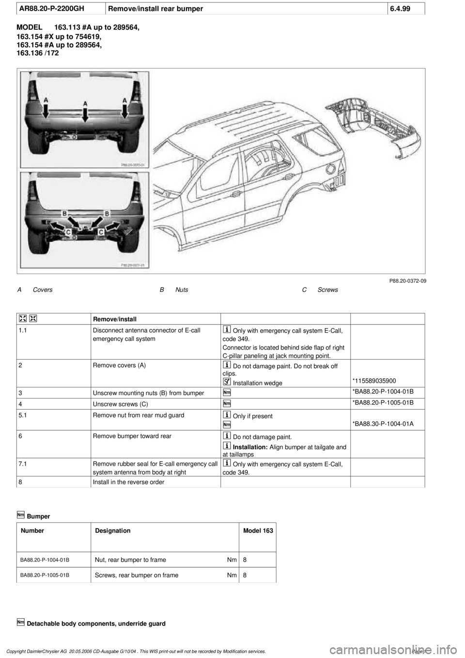
AR88.20-P-2200GH
Remove/install rear bumper
6.4.99
MODEL
163.113 #A up to 289564,
163.154 #X up to 754619,
163.154 #A up to 289564,
163.136 /172
P88.20-0372-09
A
Covers
C
Screws
B
Nuts
Remove/install
1.1
Disconnect antenna connector of E-call
emergency call system
Only with emergency call system E-Call,
code 349.
Connector is located behind side flap of right
C-pillar paneling at jack mounting point.
2
Remove covers (A)
Do not damage paint. Do not break off
clips.
Installation wedge
*115589035900
3
Unscrew mounting nuts (B) from bumper
*BA88.20-P-1004-01B
4
Unscrew screws (C)
*BA88.20-P-1005-01B
5.1
Remove nut from rear mud guard
Only if present
*BA88.30-P-1004-01A
6
Remove bumper toward rear
Do not damage paint.
Installation:
Align bumper at tailgate and
at taillamps
7.1
Remove rubber seal for E-call emergency call
system antenna from body at right
Only with emergency call system E-Call,
code 349.
8
Install in the reverse order
Bumper
Number
Designation
Model 163
BA88.20-P-1004-01B
Nut, rear bumper to frame
Nm
8
BA88.20-P-1005-01BScrews, rear bumper on frame
Nm
8
Copyright DaimlerChrysler AG 20.05.2006 CD-Ausgabe G/10/04 . This WIS print-out will not be recorde
d by Modification services.
Page 1
Page 2003 of 4133
AR88.20-P-2200GJ
Remove/install rear bumper
6.4.99
MODEL
163.113 /128 /136 /154 /157 /172 /175 with CODE (U49) Styling package
MODEL
163.174
P88.20-2090-09
Remove/install
1.1
Separate antenna of emergency call system
E-Call connector
Only with E-call emergency call system,
code 349. The connector is located behind
the side flap of the right C-pillar paneling at
the jack socket point.
2
Unscrew screws (A) on energy absorber
retaining straps at bottom of cross member
2 each.
*BA88.20-P-1005-01B
3
Pull cover strip off of screws (B) at top of
bumper
Velcro strips
4
Unscrew screws (B) at top of bumper
*BA88.20-P-1005-01B
5
Pull bumper to the rear and remove
Do not damage paintwork/wiring harness.
Installation:
Align bumper at tailgate and
at taillamps.
6.1
Remove rubber seal of antenna of emergency
call system E-Call on right at body
Only with emergency call system E-Call,
Code 349.
7.1
Disconnect connector from Parktronic system
Only with Parktronic system (PTS), code
220a. Remove left rubber seal at body.
8
Install in the reverse order
Bumper
Number
Designation
Model 163
BA88.20-P-1005-01B
Screws, rear bumper to frame
Nm
8
Copyright DaimlerChrysler AG 20.05.2006 CD-Ausgabe G/10/04 . This WIS print-out will not be recorde
d by Modification services.
Page 1
Page 2004 of 4133
AR88.20-P-2200GK
Remove/install rear bumper
26.2.01
MODEL
163.113 #A as of 289565,
163.113 #X as of 754620,
163.154 #A as of 289565,
163.128 /157 /175
P88.20-2200-09
Remove/Install
1.1
Disconnect antenna connector of E-call
emergency call system
Only with emergency call system E-Call,
code 349.
The connector is located behind side flap on
right C-pillar paneling at vehicle jacking point.
2
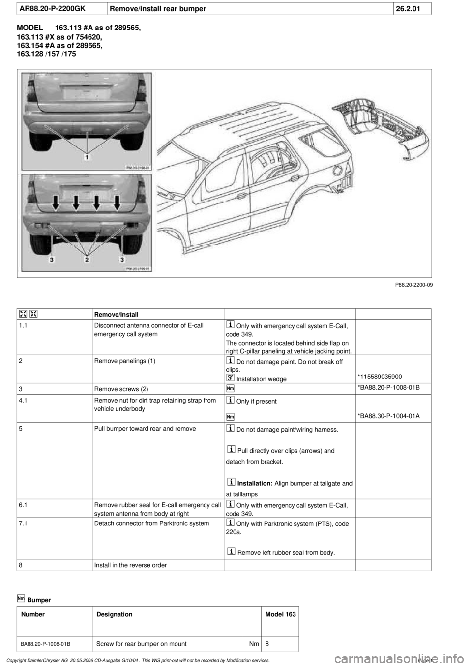
Remove panelings (1)
Do not damage paint. Do not break off
clips.
Installation wedge
*115589035900
3
Remove screws (2)
*BA88.20-P-1008-01B
4.1
Remove nut for dirt trap retaining strap from
vehicle underbody
Only if present
*BA88.30-P-1004-01A
5
Pull bumper toward rear and remove
Do not damage paint/wiring harness.
Pull directly over clips (arrows) and
detach from bracket.
Installation:
Align bumper at tailgate and
at taillamps
6.1
Remove rubber seal for E-call emergency call
system antenna from body at right
Only with emergency call system E-Call,
code 349.
7.1
Detach connector from Parktronic system
Only with Parktronic system (PTS), code
220a.
Remove left rubber seal from body.
8
Install in the reverse order
Bumper
Number
Designation
Model 163
BA88.20-P-1008-01B
Screw for rear bumper on mount
Nm
8
Copyright DaimlerChrysler AG 20.05.2006 CD-Ausgabe G/10/04 . This WIS print-out will not be recorde
d by Modification services.
Page 1
Page 2028 of 4133
GF80.20-P-0005-01GH
Central locking (CL), location of components
P80.20-0522-06
Location of components
1
Antenna
F1
Fuse and relay module
F1k15
CL rear door unlocking relay
F1k20
CL all door locking relay
F1k23
CL front right front door and rear
door unlocking relay
F1k24
CL front left front door and tank
flap unlocking relay
M14/5
Right front door CL actuating
motor
M14/6
Left front door CL actuating motor
M14/7
Tailgate CL actuating motor
M14/8
Left rear door CL actuating motor
M14/9
Right rear door CL actuating motor
M14/10
Filler flap CL actuating motor
N10
All-activity module (AAM)
Copyright DaimlerChrysler AG 17.05.2006 CD-Ausgabe G/10/04 . This WIS print-out will not be recorde
d by Modification services.
Page 1
Page 2029 of 4133

AD80.20-P-6001-43GH
CL test of electrical system motor actuation
relay
t
A
Scope of test
Measuring instrument/
Test connection
Operation/Requirement
Specified value
D
Possible cause/Remedy
1.0
Central locking locks
everything
HHT actuation
A
All doors closed and
unlocked.
All doors and
fuel tank flap
are locked
D
Individual doors are not
locked:
t
1.1
D
No door is locked:
t
1.2
1.1
Central locking unlocks
everything
HHT actuation
A
All doors closed and locked.
All doors and
fuel tank flap
are unlocked
D
Left front door and fuel
tank flap are not unlocked:
t
1.3
D
Right front door and rear
doors are not unlocked:
t
1.4
D
Tailgate is not unlocked:
t
1.5
D
No door is unlocked:
Cables, N10
1.2
Central locking relay,
lock all doors (F1k20)
Function
Replace relay (F1k20) by
relay (F1k15),
Repeat test
t
1.0
All doors and
fuel tank flap
are locked
If test 1.0 in order:
D
Relay (F1k20)
otherwise:
D
Cables
1.3
Central locking relay,
unlock left door and fuel
tank flap (F1k24)
Function
Replace relay (F1k24) by
relay (F1k15), close and
lock left front door
A
Actuation of unlocking
left front door.
Left front door
is unlocked
Value in order:
D
Relay (F1k24)
Value not in order:
D
Cables
1.4
Central locking relay,
unlock right door and
rear doors (F1k23)
Function
Replace relay (F1k23) by
(F1k15), repeat test
t
1.1
All doors and
fuel tank flap
are unlocked
If the same fault pattern
emerges when test 1.1 is
repeated:
D
Cables
D
All-Activity Module (AAM)
(N10)
Tailgate is not unlocked:
D
Relay (F1k23)
1.5
Central locking relay,
unlock tailgate (F1k15)
Function
Replace relay (F1k15) by
(F1k23), close and lock
tailgate
A
Actuation of unlocking
tailgate
Tailgate is
unlocked
Value in order:
D
Relay (F1k15)
Value not in order:
D
Cables
Copyright DaimlerChrysler AG 17.05.2006 CD-Ausgabe G/10/04 . This WIS print-out will not be recorde
d by Modification services.
Page 1