Page 3412 of 4133

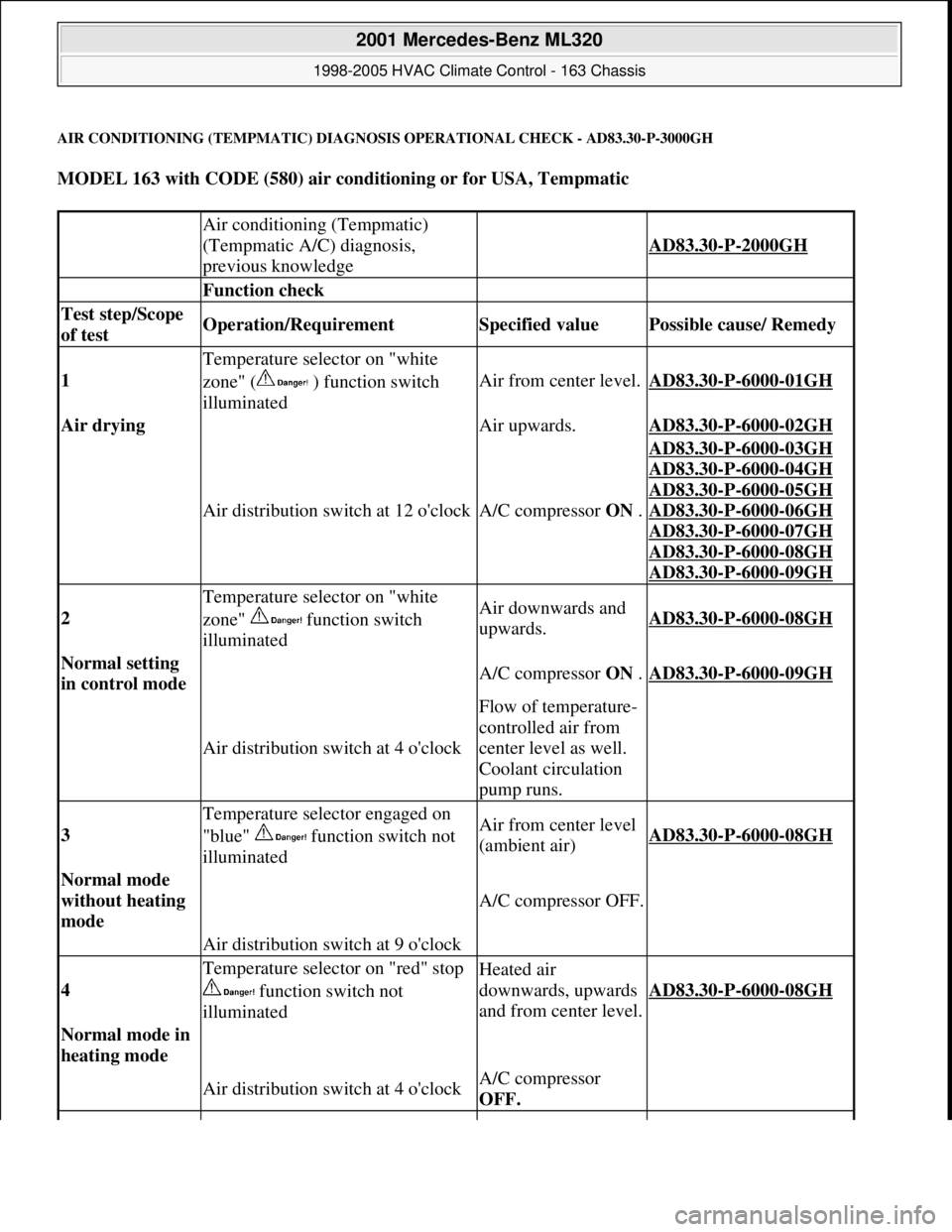
AIR CONDITIONING (TEMPMATIC) DIAGNOSIS OPERATIONAL CHECK - AD83.30-P-3000GH
MODEL 163 with CODE (580) air conditioning or for USA, Tempmatic
Air conditioning (Tempmatic)
(Tempmatic A/C) diagnosis,
previous knowledge
AD83.30-P-2000GH
Function check
Test step/Scope
of test Operation/Requirement Specified value Possible cause/ Remedy
1
Temperature selector on "white
zone" ( ) function switch
illuminated
Air from center level.AD83.30-P-6000-01GH
Air drying Air upwards.AD83.30-P-6000-02GH
Air distribution switch at 12 o'clockA/C compressor ON .
AD83.30-P-6000-03GH
AD83.30
-P-6000-04GH
AD83.30
-P-6000-05GH
AD83.30
-P-6000-06GH
AD83.30
-P-6000-07GH
AD83.30
-P-6000-08GH
AD83.30
-P-6000-09GH
2
Temperature selector on "white
zone" function switch
illuminatedAir downwards and
upwards.AD83.30-P-6000-08GH
Normal setting
in control mode A/C compressor ON .AD83.30-P-6000-09GH
Air distribution switch at 4 o'clock
Flow of temperature-
controlled air from
center level as well.
Coolant circulation
pump runs.
3
Temperature selector engaged on
"blue" function switch not
illuminatedAir from center level
(ambient air)AD83.30-P-6000-08GH
Normal mode
without heating
mode
A/C compressor OFF.
Air distribution switch at 9 o'clock
4
Temperature selector on "red" stop
function switch not
illuminatedHeated air
downwards, upwards
and from center level.
AD83.30-P-6000-08GH
Normal mode in
heating mode
Air distribution switch at 4 o'clockA/C compressor
OFF.
2001 Mercedes-Benz ML320
1998-2005 HVAC Climate Control - 163 Chassis
me
Saturday, October 02, 2010 3:23:17 PMPage 168 © 2006 Mitchell Repair Information Company, LLC.
Page 3461 of 4133
Fig. 174: Identifying Air Conditioning Control Module Components
REMOVE AND INSTALL EVAPORATOR TEMPERATURE SENSOR - AR83.30-P-8085GH
MODEL 163 with CODE (580) Air conditioning or Tempmatic for USA
Fig. 175: Identifying Evaporator Temperature Sensor Components
Removal, installation
1Disconnect ground cable of battery AR54.10-P-0003A
2Remove switch unit for heater/ ventilation (1) AR83.20-P-
1835GH
3Unscrew bolt (4) for air conditioning control module (N19) at
evaporator housing (3)
4Disconnect connector (5) at air conditioning control module (N19)
5Detach air conditioning control module (N19) from evaporator
housing (3)
6Install in the reverse order
7Encode radio AR82.60-P-7502-
01GH
8Read out diagnostic trouble code memory, erase and set clock
2001 Mercedes-Benz ML320
1998-2005 HVAC Climate Control - 163 Chassis
me
Saturday, October 02, 2010 3:23:19 PMPage 217 © 2006 Mitchell Repair Information Company, LLC.
Page 3806 of 4133

9
Install inner cover (E) at 60 % bench
Insert cover past the springs from the rear
and rotate into position in a clockwise
direction. Insert locating tabs (19). Press the
front cover down and reset so that locating
tabs (20) engage. Press rear cover down until
locating tabs (18) engage.
10
Install outer cover (D) at 60 % bench
Guide the cover past the lateral curtain.
Insert locating tab (17), push front cover down
and reset so that locating tabs (16) engage.
Press the outer edge of the cover down and
insert lateral locating tabs (15). Raise rear
cover on the inside, press down until locating
tab (14) and rear locating tab (13) engage.
11
Install curtain at front 60 % bench
12
Install inner cover (C) at 40 % bench
Insert cover from the front and insert
locating tabs (11). Press the front cover down
and reset so that locating tabs (12) engage.
13
Install outer cover (B) at 40 % bench
Guide the cover past the lateral curtain.
Insert locating tab (10), push front cover down
and reset so that locating tab (9) engages.
Press the outer edge of the cover down and
insert lateral locating tabs (8). Insert locating
tab (7), push cover down at locating tab (6)
and engage.
14
Install curtain at front 40 % bench
15
Install rear cover (A)
Insert cover from the rear and press down
and forwards so that locating tabs (5) engage.
Press front ends of the cover down, so that
locating tabs (2, 3, 4) engage. Insert locating
tabs (1) into covers (C, E).
Copyright DaimlerChrysler AG 14.06.2006 CD-Ausgabe G/10/04 . This WIS print-out will not be recorde
d by Modification services.
Page 2
Page 3811 of 4133

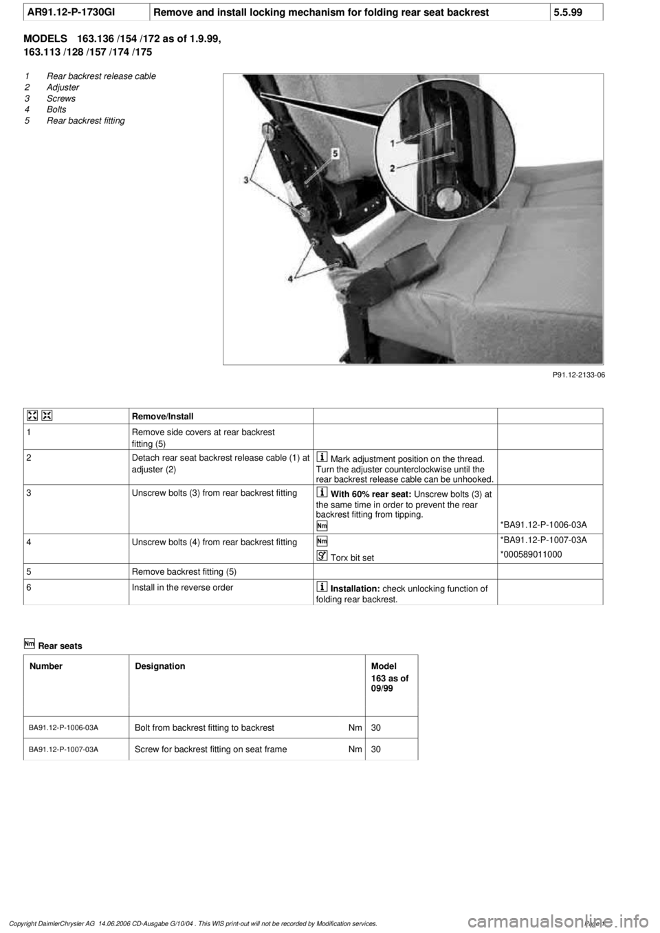
AR91.12-P-1730GI
Remove and install locking mechanism for folding rear seat backrest
5.5.99
MODELS
163.136 /154 /172 as of 1.9.99,
163.113 /128 /157 /174 /175
P91.12-2133-06
1
Rear backrest release cable
2
Adjuster
3
Screws
4
Bolts
5
Rear backrest fitting
Remove/Install
1
Remove side covers at rear backrest
fitting (5)
2
Detach rear seat backrest release cable (1) at
adjuster (2)
Mark adjustment position on the thread.
Turn the adjuster counterclockwise until the
rear backrest release cable can be unhooked.
3
Unscrew bolts (3) from rear backrest fitting
With 60% rear seat:
Unscrew bolts (3) at
the same time in order to prevent the rear
backrest fitting from tipping.
*BA91.12-P-1006-03A
4
Unscrew bolts (4) from rear backrest fitting
*BA91.12-P-1007-03A
Torx bit set
*000589011000
5
Remove backrest fitting (5)
6
Install in the reverse order
Installation:
check unlocking function of
folding rear backrest.
Rear seats
Number
Designation
Model
163 as of
09/99
BA91.12-P-1006-03A
Bolt from backrest fitting to backrest
Nm
30
BA91.12-P-1007-03A
Screw for backrest fitting on seat frame
Nm
30
Copyright DaimlerChrysler AG 14.06.2006 CD-Ausgabe G/10/04 . This WIS print-out will not be recorde
d by Modification services.
Page 1
Page 3898 of 4133

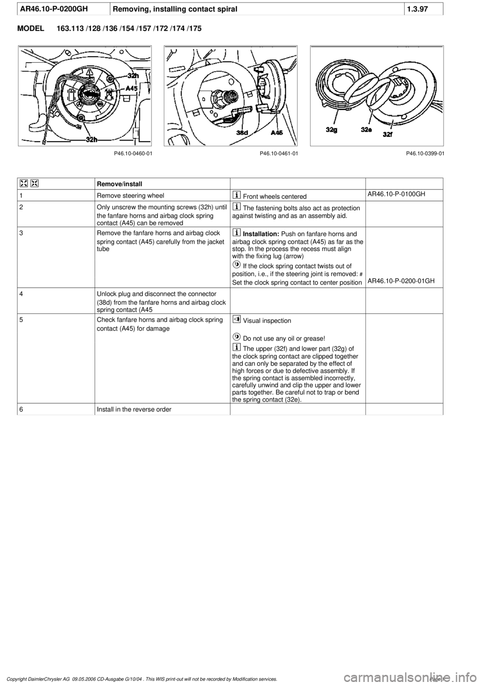
AR46.10-P-0200GH
Removing, installing contact spiral
1.3.97
MODEL
163.113 /128 /136 /154 /157 /172 /174 /175
P46.10-0460-01 P46.10-0461-01 P46.10-0399-01
Remove/install
1
Remove steering wheel
Front wheels centered
AR46.10-P-0100GH
2
Only unscrew the mounting screws (32h) until
the fanfare horns and airbag clock spring
contact (A45) can be removed
The fastening bolts also act as protection
against twisting and as an assembly aid.
3
Remove the fanfare horns and airbag clock
spring contact (A45) carefully from the jacket
tube
Installation:
Push on fanfare horns and
airbag clock spring contact (A45) as far as the
stop. In the process the recess must align
with the fixing lug (arrow)
If the clock spring contact twists out of
position, i.e., if the steering joint is removed:
#
Set the clock spring contact to center position
AR46.10-P-0200-01GH
4
Unlock plug and disconnect the connector
(38d) from the fanfare horns and airbag clock
spring contact (A45
5
Check fanfare horns and airbag clock spring
contact (A45) for damage
Visual inspection
Do not use any oil or grease!
The upper (32f) and lower part (32g) of
the clock spring contact are clipped together
and can only be separated by the effect of
high forces or due to defective assembly. If
the spring contact is assembled incorrectly,
carefully unwind and clip the upper and lower
parts together. Be careful not to trap or bend
the spring contact (32e).
6
Install in the reverse order
Copyright DaimlerChrysler AG 09.05.2006 CD-Ausgabe G/10/04 . This WIS print-out will not be recorde
d by Modification services.
Page 1
Page 3900 of 4133

5
Remove key and engage steering lock
6
Unscrew bolt (32c)
Hold the steering wheel (32).
Installation:
Replace bolt (32c).
*BA46.10-P-1001-02A
7
Pull off steering wheel (32)
Pass cables carefully through the openings.
Installation:
Align recesses of the splines
in the steering wheel with the markings on the
steering shaft (arrows).
8
Check fanfare horns and airbag clock spring
contact (A45) for damage
The clock spring contact must not be
turned while the steering wheel is removed
otherwise it will be damaged.
Visual inspection, replace clock spring
contact if necessary:
#
Removing and installing clock spring contact
AR46.10-P-0200GH
9
Install in the reverse order
10
Carry out road test
Tests during the road test:
Turn signal canceling:
When the steering wheel is offset by
more than 1 tooth, satisfactory resetting of the
turn signal is no longer guaranteed.
Airbag indicator lamp:
The SRS indicator lamp must not light up
on full steering lock in both directions.
Steering wheel position:
If the steering wheel is crooked, adjust it
by max. 1 tooth. If the difference is greater:
#
Check toe on front axle and adjust if
necessary, see:
#
Performing chassis alignment check
AR40.20-P-0200A
Steering wheel
Number
Designation
Model 163
BA46.10-P-1001-02A
Bolt, steering wheel to steering shaft
Nm
80
Copyright DaimlerChrysler AG 09.05.2006 CD-Ausgabe G/10/04 . This WIS print-out will not be recorde
d by Modification services.
Page 2