1997 MERCEDES-BENZ ML430 set clock
[x] Cancel search: set clockPage 3214 of 4133
Mode control knob controls air distribution throughout the passenger compartment. Air distribution doors are
controlled by cables activated by the mode control knob. See Fig. 1
. Four mode positions are available with
detents in-between to adjust airflow for personal comfort.
Defrost
Set mode control knob to 12-o'clock position. Air will exit from defrost outlets and side window vents.
Vent
Set mode control knob to 9-o'clock position. Air will exit from instrument panel outlets.
Floor
Set mode control knob to 6-o'clock position. Air will exit from floor outlets.
Blend/Bi-Level
Set mode control knob to 3-o'clock position. Air will exit from defrost, instrument panel, and floor outlets.
TEMPERATURE CONTROL KNOB
Air temperature is controlled by a variable resistor rotary control switch. See Fig. 1 . Switch receives voltage
signal and depending upon position, controls voltage signal sent to air mix damper door motor. See Fig. 2
.
Volta
ge controls position of motor for heating and cooling.
2001 Mercedes-Benz ML320
2000-01 MANUAL A/C-HEATER SYSTEMS ML 320, ML 430 & ML 55
me
Saturday, October 02, 2010 3:25:10 PMPage 3 © 2006 Mitchell Repair Information Company, LLC.
Page 3220 of 4133
FUNCTIONAL TEST PREPARATION
1. Check condition of fuses F16, F41, F43 and F44. See WIRING DIAGRAMS . Repair and/or replace
fuses and necessary.
2. Turn ignition on. Locate in-vehicle temperature sensor aspirator blower vent grille above anti-theft
indicator light. Place a half-inch square of tissue paper over aspirator blower vent grille. If paper stays on
vent grille, go to next step. If paper does not stay on vent grille, correct insufficient aspirator blower
ventilation.
3. Put shift lever in "P" and engage parking brake. Run engine at idle until it reaches normal operating
temperature, about 176°F (80°C). Ensure ambient (outside) temperature is greater than 58°F (15°C).
4. Manually open center and side air outlets. Ensure recirculation button is not depressed. Set blower speed
knob to position No. 1.
FUNCTION TEST
Defrost Mode
To check operation in defrost mode, set temperature selector knob to White range (vertical). Set mode control
knob to 12-o'clock position (vertical). Ensure A/C button indicator is illuminated. Air will vent from defrost and
center outlets and A/C compressor will engage. If operation is not as specified, perform the following in order:
Check voltage supply circuit Z50/2 between No. 16 fuse (15-amp) and connected components. See
VOLTAGE SUPPLY CIRCUIT Z50/2
under ELECTRICAL TESTS.
Check ground circuit. See GROUND CIRCUIT Z50/4 under ELECTRICAL TESTS.
Check in-vehicle temperature sensor signal voltage. See IN-VEHICLE TEMPERATURE SENSOR
under ELECTRICAL TESTS.
Check in-vehicle temperature sensor signal resistance. See IN-VEHICLE TEMPERATURE SENSOR
under ELECTRICAL TESTS.
Check icing protection temperature sensor signal voltage. See ICING PROTECTION
TEMPERATURE SENSOR under ELECTRICAL TESTS.
Check icing protection temperature sensor resistance. See ICING PROTECTION TEMPERATURE
SENSOR under ELECTRICAL TESTS.
Check activation voltage during temperature reduction. See ACTIVATION VOLTAGE
TEMPERATURE under ELECTRICAL TESTS.
Check activation voltage during temperature increase. See ACTIVATION VOLTAGE
TEMPERATURE under ELECTRICAL TESTS.
Check blend air flap actuator motor operation voltage. See BLEND AIR FLAP ACTUATOR MOTOR
under ELECTRICAL TESTS.
Check blend air flap actuator motor resistance. See BLEND AIR FLAP ACTUATOR MOTOR under
ELECTRICAL TESTS.
Check A/C button activation. See A/C BUTTON under ELECTRICAL TESTS.
Check A/C pressure switch. See A/C REFRIGERANT PRESSURE SWITCH under ELECTRICAL NOTE: Function test steps must be performed in order given.
2001 Mercedes-Benz ML320
2000-01 MANUAL A/C-HEATER SYSTEMS ML 320, ML 430 & ML 55
me
Saturday, October 02, 2010 3:25:10 PMPage 9 © 2006 Mitchell Repair Information Company, LLC.
Page 3221 of 4133
TESTS.
Normal Ventilation In Regulating Mode
To check normal ventilation in regulating mode, set temperature selector knob to White range (vertical). Set
mode control knob to 4-o'clock position. Ensure A/C button indicator is illuminated. Air will vent from upper
and lower outlets and A/C compressor will engage. Ambient air will flow from center outlet and coolant
circulation pump will operate. If operation is not as specified, perform the following in order:
Check A/C button activation. See A/C BUTTON under ELECTRICAL TESTS.
Check A/C pressure switch. See A/C REFRIGERANT PRESSURE SWITCH under ELECTRICAL
TESTS.
Economy Setting Not In Heating Mode
To check economy setting without heating mode activated, set temperature selector knob to Blue range. Set
mode control knob to the 9-o'clock position. Ensure A/C button indicator is not illuminated. Ambient air will
flow from center outlet and A/C compressor will NOT be engaged. If operation is not as specified, perform the
following:
Check A/C button activation. See A/C BUTTON under ELECTRICAL TESTS.
Economy Setting In Heating Mode
To check economy setting with heating mode activated, set temperature selector knob to Red range. Set mode
control knob to the 4-o'clock position. Ensure A/C button indicator is not illuminated. Heated air will flow from
lower, upper and center outlets and A/C compressor will NOT be engaged. If operation is not as specified,
perform the following:
Check A/C button activation. See A/C BUTTON under ELECTRICAL TESTS.
Recirculation Mode
To check recirculation mode, press fresh/recirculation button. Ensure fresh/recirculation indicator is
illuminated. Set blower speed knob to position No. 4. Blower fan noise will increase noticeably. If operation is
not as specified, check wiring between recirculated air flap element, heater-A/C switch and No. 16 fuse (15-
amp).
ELECTRICAL TESTS
Voltage Supply Circuit Z50/2
1. Connect socket box to A/C push button control unit and wiring harness. See CONNECTING TEST
EQUIPMENT . Turn ignition on, with engine off. Connect voltmeter positive lead to socket box terminal
No. 7 and negative lead to terminal No. 9.
2. Voltage should be 11-14 volts. If voltage is not as specified, check voltage supply circuit Z50/2 between
No. 16 fuse (15-amp) and connected components. See WIRING DIAGRAMS
. Repair as necessary.
2001 Mercedes-Benz ML320
2000-01 MANUAL A/C-HEATER SYSTEMS ML 320, ML 430 & ML 55
me
Saturday, October 02, 2010 3:25:10 PMPage 10 © 2006 Mitchell Repair Information Company, LLC.
Page 3228 of 4133
A/C housing. Disconnect control module connector. To install reverse removal procedure. Recode 5-digit radio
security code. Using HHT, check for DTC and erase, and set clock.
A/C PUSH BUTTON CONTROL PANEL
Removal & Installation
1. Obtain 5-digit radio security code from vehicle owner. Disconnect negative battery cable. Using radio
removal plates, remove radio. Disconnect electrical connectors.
2. Remove instrument panel center section. Remove 4 A/C control panel screws and remove control panel.
Release pull cables and disconnect connectors. To install, reverse removal procedure. Recode radio. See
RECODING RADIO
under PROGRAMMING.
BLOWER MOTOR
Removal & Installation
Remove passenger-side instrument panel under cover. Remove blower motor mounting screws from A/C
housing unit. Disconnect blower motor connector and remove blower motor. To install, reverse removal
procedure.
COMPRESSOR
Removal & Installation
1. Discharge A/C system, using approved refrigerant recovery/recycling equipment. Remove accessory
drive belt. Disconnect low pressure refrigerant line from compressor. Discard "O" rings. Plug exposed
openings to protect A/C system from debris and moisture.
2. Disconnect high pressure refrigerant line from compressor. Discard "O" rings. Plug exposed openings to
protect A/C system from debris and moisture. Disconnect electrical connector. Remove compressor
mounting bolts.
3. Raise and support vehicle. Remove compressor from under vehicle without spilling refrigerant oil. To
install, reverse removal procedure. Ensure refrigerant oil quantity in compressor is correct. See
COMPRESSOR REFRIGERANT OIL CHECKING under GENERAL SERVICING. Tighten bolts to
specification. See TORQUE SPECIFICATIONS
.
CONDENSER
Removal & Installation
1. Discharge A/C system, using approved refrigerant recovery/recycling equipment. Remove cooling fans.
See COOLING FANS
. Disconnect refrigerant line from receiver-drier. See Fig. 5 . Discard "O" rings.
2. Plug exposed openings to protect A/C system from debris and moisture. Remove refrigerant line from
condenser. Remove radiator upper rubber seal. See Fig. 6
. Remove condenser upper mounting screws.
Lift condenser upward and remove. NOTE: Each time A/C compressor is removed and installed, receiver-drier must be
replaced.
2001 Mercedes-Benz ML320
2000-01 MANUAL A/C-HEATER SYSTEMS ML 320, ML 430 & ML 55
me
Saturday, October 02, 2010 3:25:10 PMPage 17 © 2006 Mitchell Repair Information Company, LLC.
Page 3268 of 4133
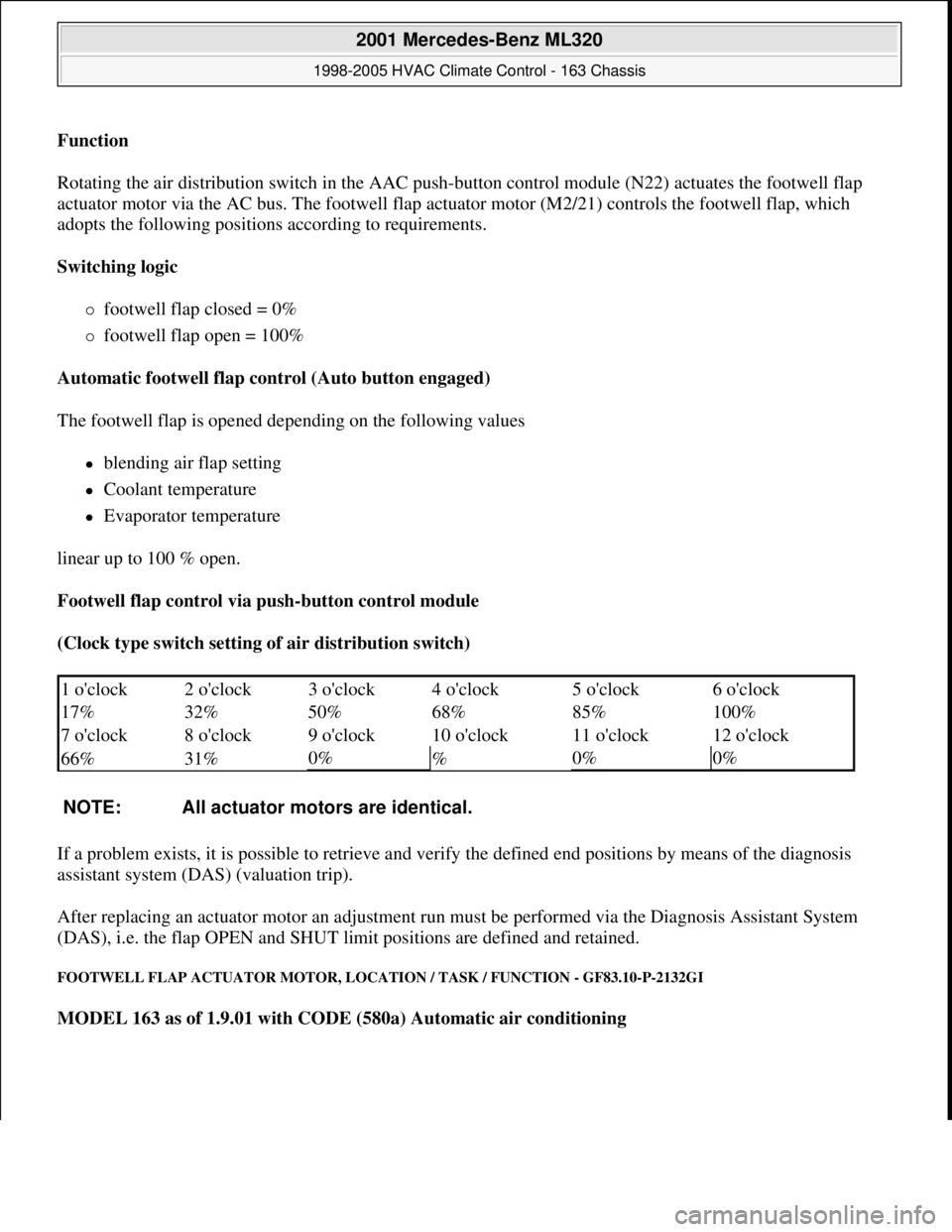
Function
Rotating the air distribution switch in the AAC push-button control module (N22) actuates the footwell flap
actuator motor via the AC bus. The footwell flap actuator motor (M2/21) controls the footwell flap, which
adopts the following positions according to requirements.
Switching logic
footwell flap closed = 0%
footwell flap open = 100%
Automatic footwell flap control (Auto button engaged)
The footwell flap is opened depending on the following values
blending air flap setting
Coolant temperature
Evaporator temperature
linear up to 100 % open.
Footwell flap control via push-button control module
(Clock type switch setting of air distribution switch)
If a problem exists, it is possible to retrieve and verify the defined end positions by means of the diagnosis
assistant system (DAS) (valuation trip).
After replacing an actuator motor an adjustment run must be performed via the Diagnosis Assistant System
(DAS), i.e. the flap OPEN and SHUT limit positions are defined and retained.
FOOTWELL FLAP ACTUATOR MOTOR, LOCATION / TASK / FUNCTION - GF83.10-P-2132GI
MODEL 163 as of 1.9.01 with CODE (580a) Automatic air conditioning
1 o'clock 2 o'clock 3 o'clock 4 o'clock 5 o'clock6 o'clock
17% 32% 50% 68% 85%
100%
7 o'clock 8 o'clock 9 o'clock 10 o'clock 11 o'clock
12 o'clock
66% 31%
0%
%0%0%
NOTE: All actuator motors are identical.
2001 Mercedes-Benz ML320
1998-2005 HVAC Climate Control - 163 Chassis
me
Saturday, October 02, 2010 3:23:15 PMPage 24 © 2006 Mitchell Repair Information Company, LLC.
Page 3280 of 4133
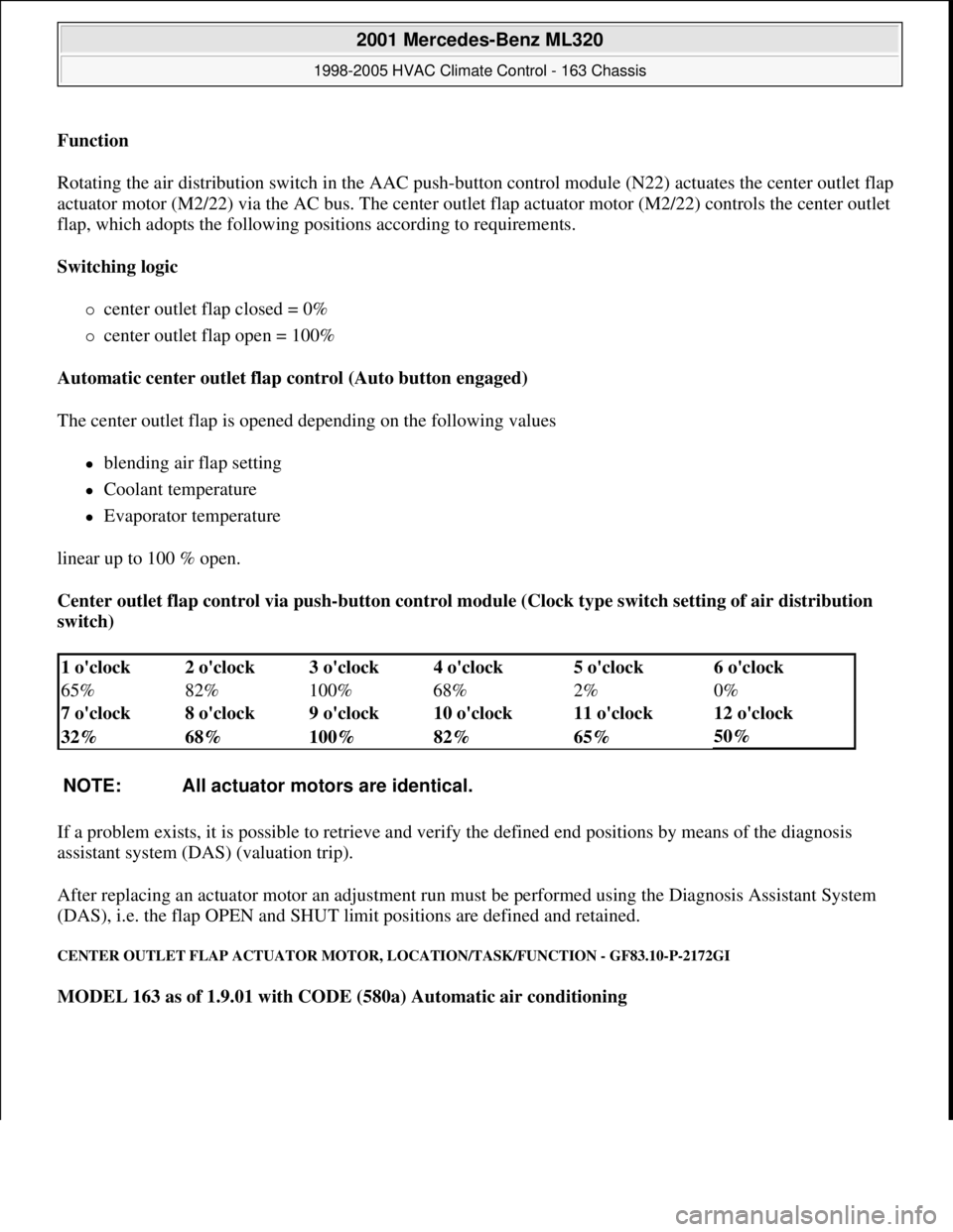
Function
Rotating the air distribution switch in the AAC push-
button control module (N22) actuates the center outlet flap
actuator motor (M2/22) via the AC bus. The center outlet flap actuator motor (M2/22) controls the center outlet
flap, which adopts the following positions according to requirements.
Switching logic
center outlet flap closed = 0%
center outlet flap open = 100%
Automatic center outlet flap control (Auto button engaged)
The center outlet flap is opened depending on the following values
blending air flap setting
Coolant temperature
Evaporator temperature
linear up to 100 % open.
Center outlet flap control via push-button control module (Clock type switch setting of air distribution
switch)
If a problem exists, it is possible to retrieve and verify the defined end positions by means of the diagnosis
assistant system (DAS) (valuation trip).
After replacing an actuator motor an adjustment run must be performed using the Diagnosis Assistant System
(DAS), i.e. the flap OPEN and SHUT limit positions are defined and retained.
CENTER OUTLET FLAP ACTUATOR MOTOR, LOCATION/TASK/FUNCTION - GF83.10-P-2172GI
MODEL 163 as of 1.9.01 with CODE (580a) Automatic air conditioning
1 o'clock 2 o'clock 3 o'clock 4 o'clock 5 o'clock6 o'clock
65% 82% 100% 68% 2%
0%
7 o'clock 8 o'clock 9 o'clock 10 o'clock 11 o'clock
12 o'clock
32% 68% 100% 82% 65%
50%
NOTE: All actuator motors are identical.
2001 Mercedes-Benz ML320
1998-2005 HVAC Climate Control - 163 Chassis
me
Saturday, October 02, 2010 3:23:15 PMPage 36 © 2006 Mitchell Repair Information Company, LLC.
Page 3283 of 4133
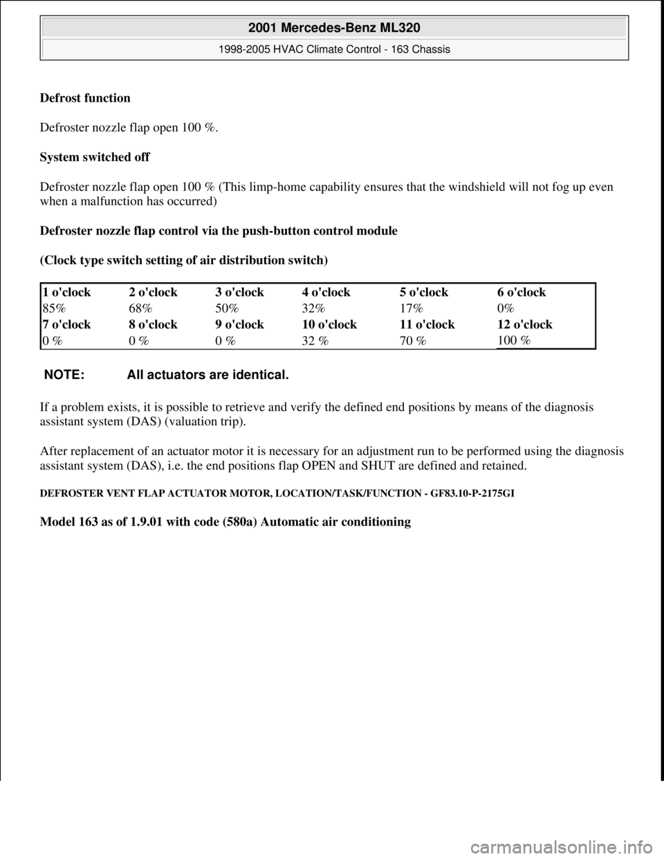
Defrost function
Defroster nozzle flap open 100 %.
System switched off
Defroster nozzle flap open 100 % (This limp-home capability ensures that the windshield will not fog up even
when a malfunction has occurred)
Defroster nozzle flap control via the push-button control module
(Clock type switch setting of air distribution switch)
If a problem exists, it is possible to retrieve and verify the defined end positions by means of the diagnosis
assistant system (DAS) (valuation trip).
After replacement of an actuator motor it is necessary for an adjustment run to be performed using the diagnosis
assistant system (DAS), i.e. the end positions flap OPEN and SHUT are defined and retained.
DEFROSTER VENT FLAP ACTUATOR MOTOR, LOCATION/TASK/FUNCTION - GF83.10-P-2175GI
Model 163 as of 1.9.01 with code (580a) Automatic air conditioning
1 o'clock 2 o'clock 3 o'clock 4 o'clock 5 o'clock6 o'clock
85% 68% 50% 32% 17%
0%
7 o'clock 8 o'clock 9 o'clock 10 o'clock 11 o'clock
12 o'clock
0 % 0 % 0 % 32 % 70 %
100 %
NOTE: All actuators are identical.
2001 Mercedes-Benz ML320
1998-2005 HVAC Climate Control - 163 Chassis
me
Saturday, October 02, 2010 3:23:15 PMPage 39 © 2006 Mitchell Repair Information Company, LLC.
Page 3302 of 4133
clockwise direction to the final indented position (max. cooling), the recirculation switch is bypassed and thus
the fresh air flaps closed, in order to achieve the max. interior cooling (with A/C ON).
TEMPERATURE SELECTOR WHEEL, FUNCTION - GF83.25-P-2102-01GI
Function
The desired in-car temperature is set by turning the temperature selector wheel on the AAC push-button control
module (N22).
The AAC push-button control module (N22) compares the desired temperature with the temperature in the
passenger compartment. The passenger compartment temperature is determined by the in-car temperature
sensor on the AAC push-button control module (N22) and the temperature sensor for the vent air at the center
nozzle, front and rear footwells.
Using the comparison between specified and actual values, the AAC push-button control module (N22)
determines the correct setting of the blending air flaps and actuates these. The selected temperature is reached
and maintained as quickly as possible, if warming or cooling of the interior is necessary.
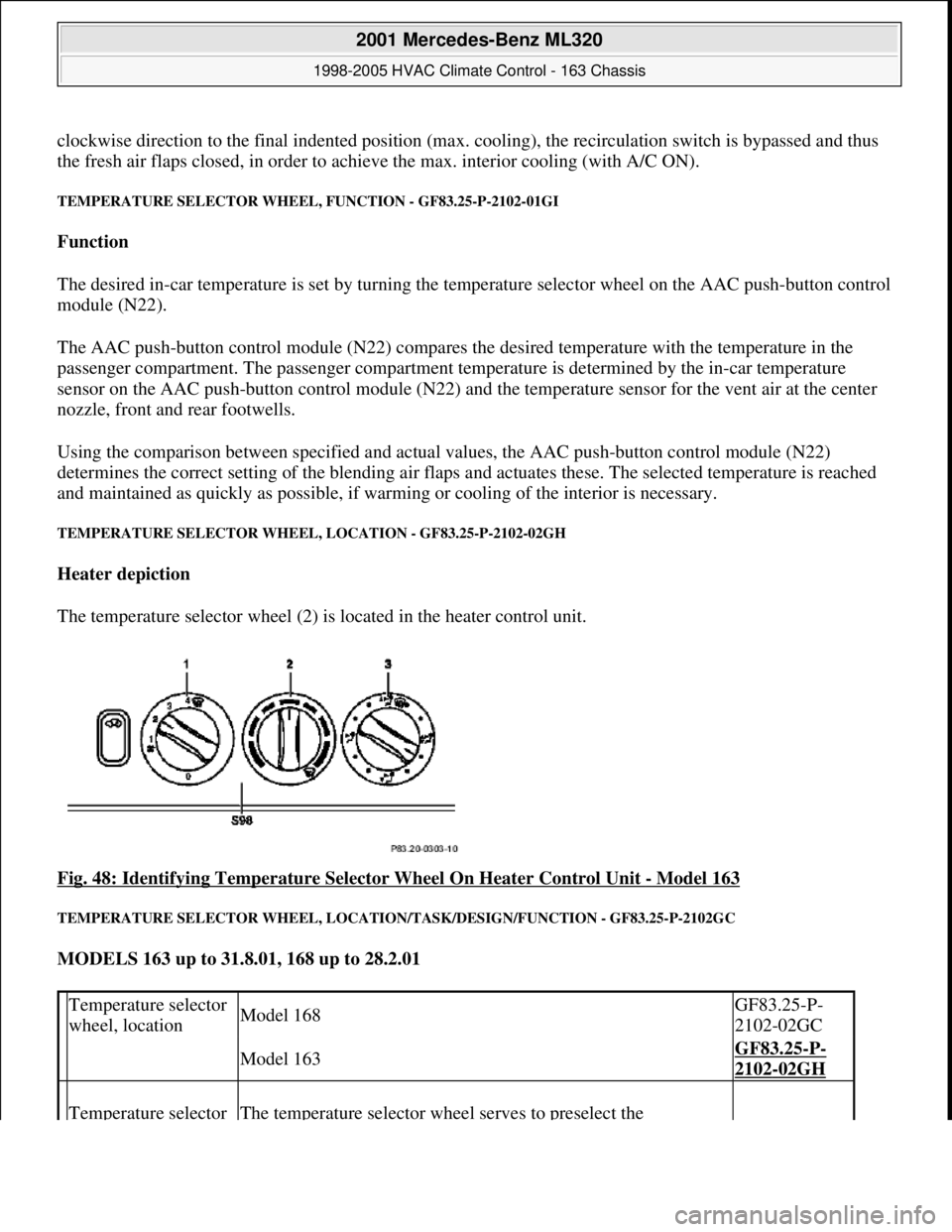
TEMPERATURE SELECTOR WHEEL, LOCATION - GF83.25-P-2102-02GH
Heater depiction
The temperature selector wheel (2) is located in the heater control unit.
Fig. 48: Identifying Temperature Selector Wheel On Heater Control Unit
- Model 163
TEMPERATURE SELECTOR WHEEL, LOCATION/TASK/DESIGN/FUNCTION - GF83.25-P-2102GC
MODELS 163 up to 31.8.01, 168 up to 28.2.01
Temperature selector
wheel, locationModel 168GF83.25-P-
2102-02GC
Model 163GF83.25-P-
2102-02GH
Temperature selector The temperature selector wheel serves to preselect the
2001 Mercedes-Benz ML320
1998-2005 HVAC Climate Control - 163 Chassis
me
Saturday, October 02, 2010 3:23:15 PMPage 58 © 2006 Mitchell Repair Information Company, LLC.