1997 MERCEDES-BENZ ML430 set clock
[x] Cancel search: set clockPage 1177 of 4133
Fig. 4: Removing & Installing Transmission With Torque Converter
Courtesy of MERCEDES-BENZ OF NORTH AMERICA.
Remove/Install -
1 - Disconnect ground cable of battery. See DISCONNECT GROUND LEAD FROM BATTERY
.
2 - Remove transfer case. See TRANSFER CASE .
3 - Unbolt oil filler pipe (3) from crankcase. See Fig. 4
.
4 - Remove heat shield (5) and disconnect 13-pin plug connector (2).
5 - Remove locking clips (21) and remove shift.
6 - Unscrew oil drain screw on oil pan (14).
7.1 - Unscrew oil drain screw for torque converter (15).
8.1 - Detach wire for park lock interlock (7) at transmission.
9 - Lambda sensors for primary catalytic converters remove.
10 - Unscrew oil lines (4) to oil cooler from transmission.
11 - Remove cover in oil pan (18) and disconnect torque converter from driven plate at flange.
12 - Unscrew bolts of transmission (19) at crankcase and take out transmission downwards at an angle
using a lifting device. NOTE: Code radio, set clock, normalize power windows and set timer in vehicles
with stationary heater.
NOTE: Adjust shift rod using pliers. See Fig. 10
.
NOTE: If the transmission fluid is burnt or contains wear particles, the oil cooler
lines and oil cooler must be flushed out: Flush oil cooler and oil cooler
lines.
NOTE: Only up to A145272,X708318. For installation and removal, position
selector lever or range selector lever in position "P" and leave in position
"P" when cable/transmission is removed. See REMOVING & INSTALLING
WIRE CABLE/TRANSMISSION FOR PARKING SHIFT LOCK ON
TRANSMISSION.
NOTE: Only up to A145272, X708318.
Upon Installation: Adjust cables for parking shift lock. See ADJUSTING
WIRE CABLES FOR PARKING LOCK INTERLOCK.
NOTE: Upon Installation: Check function of parking shift lock.
2001 Mercedes-Benz ML320
1998-03 AUTOMATIC TRANSMISSIONS Complete Transmissions - ML 320 - 722.662
me
Saturday, October 02, 2010 3:15:25 PMPage 8 © 2006 Mitchell Repair Information Company, LLC.
Page 1492 of 4133

9
Install inner cover (E) at 60 % bench
Insert cover past the springs from the rear
and rotate into position in a clockwise
direction. Insert locating tabs (19). Press the
front cover down and reset so that locating
tabs (20) engage. Press rear cover down until
locating tabs (18) engage.
10
Install outer cover (D) at 60 % bench
Guide the cover past the lateral curtain.
Insert locating tab (17), push front cover down
and reset so that locating tabs (16) engage.
Press the outer edge of the cover down and
insert lateral locating tabs (15). Raise rear
cover on the inside, press down until locating
tab (14) and rear locating tab (13) engage.
11
Install curtain at front 60 % bench
12
Install inner cover (C) at 40 % bench
Insert cover from the front and insert
locating tabs (11). Press the front cover down
and reset so that locating tabs (12) engage.
13
Install outer cover (B) at 40 % bench
Guide the cover past the lateral curtain.
Insert locating tab (10), push front cover down
and reset so that locating tab (9) engages.
Press the outer edge of the cover down and
insert lateral locating tabs (8). Insert locating
tab (7), push cover down at locating tab (6)
and engage.
14
Install curtain at front 40 % bench
15
Install rear cover (A)
Insert cover from the rear and press down
and forwards so that locating tabs (5) engage.
Press front ends of the cover down, so that
locating tabs (2, 3, 4) engage. Insert locating
tabs (1) into covers (C, E).
Copyright DaimlerChrysler AG 12.06.2006 CD-Ausgabe G/10/04 . This WIS print-out will not be recorde
d by Modification services.
Page 2
Page 1717 of 4133
Audio 30 APS operating
notes GF82.61-P-0002-03A
Audio 30 APS location of
componentsModel 163GF82.61-P-0002-01D
Model 168GF82.61-P-0002-01B
Model 170GF82.61-P-0002-01A
Models 208, 210GF82.61-P-0002-01C
Audio 30 APS diagnosis,
previous knowledge AD82.61-P-2001A
Battery voltage 11-14V
Troubleshooting
Complaint Cause Note Remedy
Radio and navigation
unit (A2/56) completely
inoperativeFuse in A2/56, Voltage
supply for A2/56, Defect at
navigation CD-ROM,
A2/56 AD82.61-P-6001-01A
No communication
possible between Hand-
Held Tester (HHT) and
Audio 30 APSK line, Radio and
navigation unit (A2/56) AD82.61-P-6001-02A
Navigation inoperative Navigation CD-ROM is not
loaded or is incorrectly
loaded or incorrect /
defective CD-ROM
Radio and navigation unit
(A2/56) Load navigation CD,
refer to:
GF82.61
-P-0002-03A
Destination finding
system messages are
given too early or too late
(e.g. "please turn right")Check wheel calibration
and variant coding AD82.61-P-2001-03A
The expected arrival
time is not correctTime on radio and
navigation unit (A2/56) is
incorrectly set Actuate "NAV"
pushbutton and activate
"CLOCK" menu, set
time
Navigation is defective
or impreciseCheck variant coding and
wheel calibration,
Reversing signal,
Wheel speed signal,
Models 163, 168, 208.3,
210:
Cellular telephone and GPS
roof antenna (A2/49),
Models 170, 208.4:
GPS rear antenna
(A2/23a2) Models 163, 168, 170
Models 208, 210Refer to:
AD82.61
-P-2001-03A
AD82.61
-P-6001-04A
AD82.61-P-6001-04B
AD82.61
-P-6001-03A
AD82.61-P-6001-05A
2001 Mercedes-Benz ML320
1998-2005 ACCESSORIES & BODY, CAB Electrical System - Body - 163 Chassis
me
Saturday, October 02, 2010 3:30:08 PMPage 222 © 2006 Mitchell Repair Information Company, LLC.
Page 1753 of 4133
REMOVE/INSTALL XENON HEADLAMP CONTROL UNIT - AR82.10-P-4632GH
MODEL 163.113 #X up to 754619, 163.113 /154 #A up to 289564, 163.172 with CODE (612) Xenon
UV light, hot
components on xenon
headlamps and glass
splinters when xenon
bulbs burst
Risk of poisoning
through inhalation of
mercury vapor and
swallowing of or skin
contact with toxic salts
and mercury compoundsprotective gloves. Remove
highly inflammable
materials from the hazard
area. Ensure that the
workplace is sufficiently
ventilated.
1Remove left front lamp
unit (E1) or right front
lamp unit (E2) AR82.10-P-4730GH
2Remove cover from rear
of lamp unit
3Turn left headlamp range
adjustment motor
(E1m1) or right
headlamp range
adjustment motor
(E2m1) to right and
remove from left front
lamp unit (E1) or right
front lamp unit (E2) Left side: 1/4 clockwise
rotation. Right side: 1/4
counterclockwise rotation.
4Unhook adjusting
support and remove left
headlamp range
adjustment motor
(E1m1) or right
headlamp range
adjustment (E2m1)
5Install in the reverse
order
6Set headlamps to zero
position using STAR
DIAGNOSIS
7Inspect headlamp
adjustment, correct if
necessary.
Check and correct
headlamp adjustment AP82.10-P-8260GH
2001 Mercedes-Benz ML320
1998-2005 ACCESSORIES & BODY, CAB Electrical System - Body - 163 Chassis
me
Saturday, October 02, 2010 3:30:09 PMPage 258 © 2006 Mitchell Repair Information Company, LLC.
Page 1755 of 4133
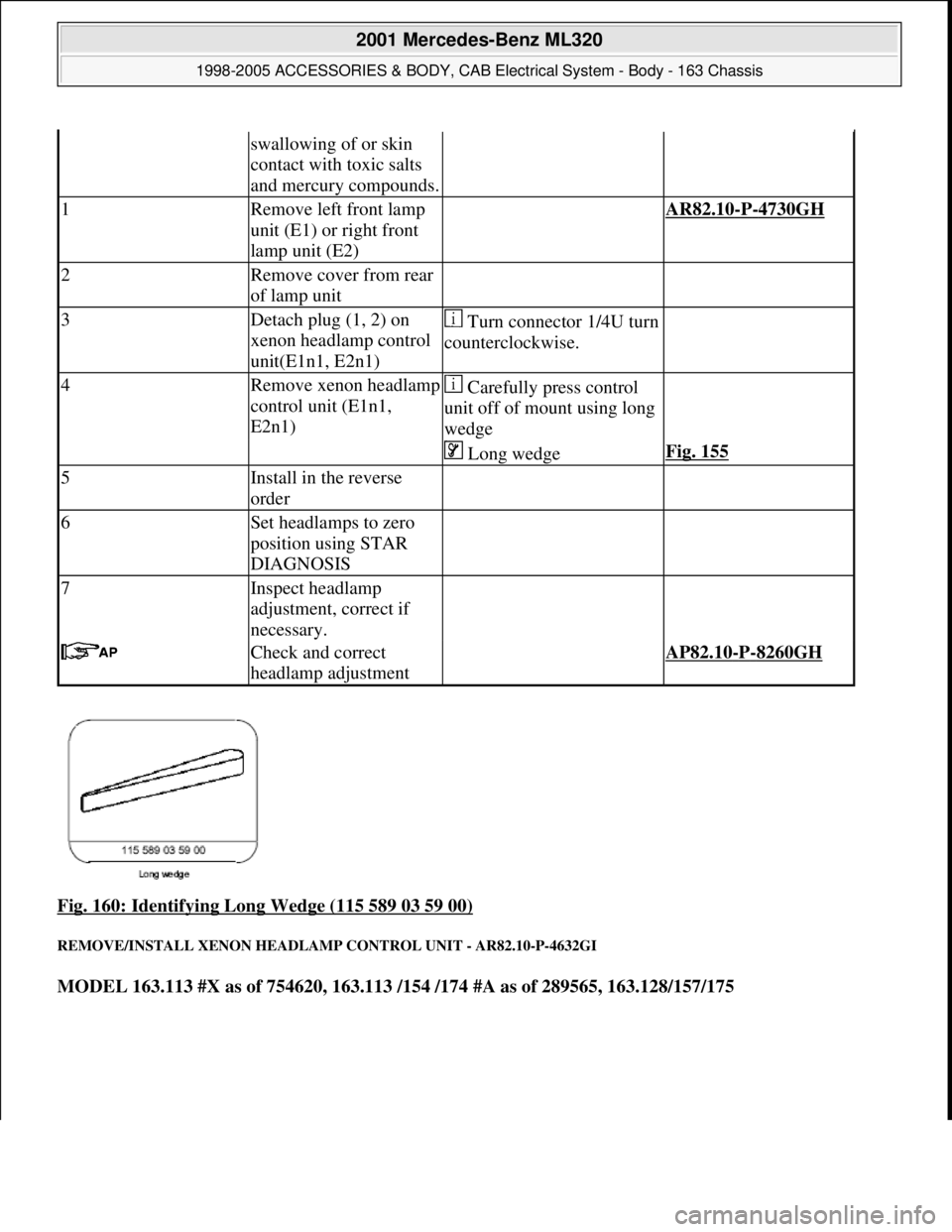
Fig. 160: Identifying Long Wedge (115 589 03 59 00)
REMOVE/INSTALL XENON HEADLAMP CONTROL UNIT - AR82.10-P-4632GI
MODEL 163.113 #X as of 754620, 163.113 /154 /174 #A as of 289565, 163.128/157/175
swallowing of or skin
contact with toxic salts
and mercury compounds.
1Remove left front lamp
unit (E1) or right front
lamp unit (E2) AR82.10-P-4730GH
2Remove cover from rear
of lamp unit
3Detach plug (1, 2) on
xenon headlamp control
unit(E1n1, E2n1)Turn connector 1/4U turn
counterclockwise.
4Remove xenon headlamp
control unit (E1n1,
E2n1) Carefully press control
unit off of mount using long
wedge
Long wedgeFig. 155
5Install in the reverse
order
6Set headlamps to zero
position using STAR
DIAGNOSIS
7Inspect headlamp
adjustment, correct if
necessary.
Check and correct
headlamp adjustment AP82.10-P-8260GH
2001 Mercedes-Benz ML320
1998-2005 ACCESSORIES & BODY, CAB Electrical System - Body - 163 Chassis
me
Saturday, October 02, 2010 3:30:09 PMPage 260 © 2006 Mitchell Repair Information Company, LLC.
Page 2042 of 4133
3. Normalize side power windows. See NORMALIZING POWER WINDOWS .
4. Start engine and run at idle. Turn steering wheel from one lock position to the other to activate steering
angle sensor. Center steering wheel. Message "EI. STAB. PROGRAM GO TO GARAGE" should erase
from multifunction display panel.
5. If equipped, normalize tilting/sliding roof. See NORMALIZING TILTING/SLIDING ROOF
.
6. If equipped, normalize memory power seats, steering column and outside mirror if components are
installed. See NORMALIZING MEMORY POWER SEATS, STEERING COLUMN & OUTSIDE
MIRROR .
Normalizing Power Windows
1. Completely close each window with manual switch. Hold switch in closed position for .3 second.
2. Repeat procedure for each power window.
Normalizing Memory Power Seats, Steering Column & Outside Mirror
1. Using manual switch, move seat to each end position and hold for .3 second. Repeat procedure for each
switch except rear stop of backrest.
2. Repeat procedure for end positions of steering wheel and outside mirrors.
Normalizing Tilting/Sliding Roof
Open roof with SR switch until mechanical stop is reached. Continue to press switch for .5 seconds.
Setting Time
1. Use bottom left button on steering wheel to scroll through menus on instrument cluster to "Settings"
menu.
2. Move selection marker with + or - button to "Time" submenu.
3. Press up or down arrows to "Clock, hours" setting. Confirm selection marker is on the hour setting.
4. Press + or - to set hour. Press reset knob in instrument cluster to confirm.
5. Move selection marker with + or - button to "Time" submenu.
6. Press up or down arrows to "Clock, minutes" setting. Confirm selection marker is on the minutes setting.
7. Press + or - to set minute. Press reset knob in instrument cluster to confirm.
TESTING
If generator malfunctions, check for Diagnostic Trouble Codes (DTCs) in Motor Electronics Sequential Fuel
Injection (ME-SFI) system. See appropriate SELF-DIAGNOSTICS article in ENGINE PERFORMANCE. If
cause of generator malfunction is not engine performance related, replace generator.
RETRIEVING & ERASING DIAGNOSTIC TROUBLE CODES
NOTE: Before replacing any component that scan tool suggests are faulty, ensure that
all wiring connections and harness connectors are okay. Ensure that power and
2001 Mercedes-Benz ML320
2001-04 STARTING & CHARGING SYSTEMS Generators & Regulators - 163 Chassis
me
Saturday, October 02, 2010 3:20:32 PMPage 8 © 2006 Mitchell Repair Information Company, LLC.
Page 2066 of 4133

GF54.30-P-2004A
Control buttons, location/task
24.10.96
MODEL
129, 140 as of 1.6.96,
163, 170
The instrument cluster has two control buttons which are on the left
or right next to the speedometer.
The
right control button
is used to adjust the time (refer to Owner's
Manual).
-----------------------------------------------------------------------------------------
The
left control button
is used
D
to regulate the instrument illumination
D
to activate the display illumination
D
to reset the trip odometer display
D
to operate the maintenance display (model 170 only bis 05.97)
D
to operate the Active Service System ASSYST (as of 06.97)
-----------------------------------------------------------------------------------------
n
Purpose/function of terminal 58d, instrument
display illumination
Engines 112, 113, 611 (engines with oil
sensor)
GF54.30-P-3008A
n
Electronic clock
GF54.30-P-3011A
n
Active Service System (ASSYST)
GF00.20-P-0003-01A
Operating instructions, resetting
Model 210 as of 01.03.97 with engines M111,
OM 602, OM 604, OM 605 and
OM 606
As of 06/97 models 129, 140, 170, 202 except
engines 112, 113, 611
(valid for engines with oil level switch)
GF00.20-P-0003-01B
Copyright DaimlerChrysler AG 05.06.2006 CD-Ausgabe G/10/04 . This WIS print-out will not be recorde
d by Modification services.
Page 1
Page 2079 of 4133

9
Install inner cover (E) at 60 % bench
Insert cover past the springs from the rear
and rotate into position in a clockwise
direction. Insert locating tabs (19). Press the
front cover down and reset so that locating
tabs (20) engage. Press rear cover down until
locating tabs (18) engage.
10
Install outer cover (D) at 60 % bench
Guide the cover past the lateral curtain.
Insert locating tab (17), push front cover down
and reset so that locating tabs (16) engage.
Press the outer edge of the cover down and
insert lateral locating tabs (15). Raise rear
cover on the inside, press down until locating
tab (14) and rear locating tab (13) engage.
11
Install curtain at front 60 % bench
12
Install inner cover (C) at 40 % bench
Insert cover from the front and insert
locating tabs (11). Press the front cover down
and reset so that locating tabs (12) engage.
13
Install outer cover (B) at 40 % bench
Guide the cover past the lateral curtain.
Insert locating tab (10), push front cover down
and reset so that locating tab (9) engages.
Press the outer edge of the cover down and
insert lateral locating tabs (8). Insert locating
tab (7), push cover down at locating tab (6)
and engage.
14
Install curtain at front 40 % bench
15
Install rear cover (A)
Insert cover from the rear and press down
and forwards so that locating tabs (5) engage.
Press front ends of the cover down, so that
locating tabs (2, 3, 4) engage. Insert locating
tabs (1) into covers (C, E).
Copyright DaimlerChrysler AG 28.05.2006 CD-Ausgabe G/10/04 . This WIS print-out will not be recorde
d by Modification services.
Page 2