Page 2163 of 4133
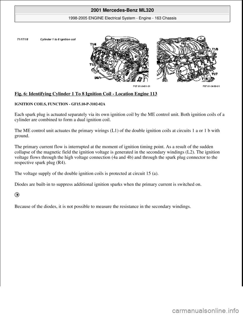
Fig. 6: Identifying Cylinder 1 To 8 Ignition Coil - Location Engine 113
IGNITION COILS, FUNCTION - GF15.10-P-3102-02A
Each spark plug is actuated separately via its own ignition coil by the ME control unit. Both ignition coils of a
cylinder are combined to form a dual ignition coil.
The ME control unit actuates the primary wirings (L1) of the double ignition coils at circuits 1 a or 1 b with
ground.
The primary current flow is interrupted at the moment of ignition timing point. As a result of the sudden
collapse of the magnetic field the ignition voltage is generated in the secondary windings (L2). The ignition
voltage flows through the high voltage connection (4a and 4b) and through the spark plug connector to the
respective spark plug (R4).
The voltage supply of the double ignition coils is protected at circuit 15 (a).
Diodes are built-in to suppress additional ignition sparks when the primary current is switched on.
Because of the diodes, it is not possible to measure the resistance in the secondary windings.
2001 Mercedes-Benz ML320
1998-2005 ENGINE Electrical System - Engine - 163 Chassis
me
Saturday, October 02, 2010 3:18:54 PMPage 9 © 2006 Mitchell Repair Information Company, LLC.
Page 2186 of 4133
Parts ordering notes
TESTING & REPAIR
TESTING AND REPAIR WORK: PASSENGER CARS: ELECTRICAL SYSTEM - ENGINE - AR15.00-Z-9163AA
MODEL 163
REMOVE, INSTALL CAMSHAFT HALL SENSOR - AR15.10-P-2000A
ENGINE 112.945 in MODEL 463.209 /232 /233 /244 /245 /250
ENGINE 112 in MODEL 129, 163, 170, 202, 203, 208, 209.361 /365/461 /465, 210,
211.061 /261 /065 /265 /080 /082 /280 /282, 220, 230.467
ENGINE 113 (except 113.990/991) in MODEL 129, 163, 202, 208, 209.375/475/376/476, 210,
211.070 /270 /083 /283, 215, 220, 230.472 /474 /475
ENGINE 113.962 in MODEL 463.206 /240 /241 /247 /248 /249 /254
ENGINE 113.982 in MODEL 463.243/246
quantity of paste is not
applied because this can
interfere with the signal
pickup of position sensor
L5
3 Install starter.
Part no.DesignationQuantity
000 989 76 51Paste (1 kg)1
Servicing wiring harnessMODEL 124, 126, 129,
140, 163, 168, 170, 201,
202, 208, 210, 215, 220AR15.18-P-0500A
2001 Mercedes-Benz ML320
1998-2005 ENGINE Electrical System - Engine - 163 Chassis
me
Saturday, October 02, 2010 3:18:54 PMPage 32 © 2006 Mitchell Repair Information Company, LLC.
Page 2202 of 4133
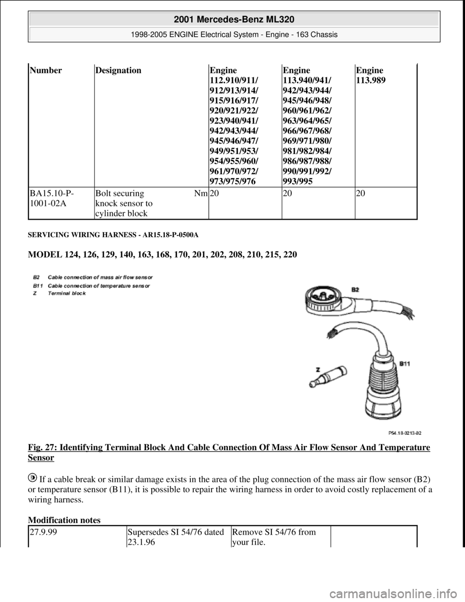
SERVICING WIRING HARNESS - AR15.18-P-0500A
MODEL 124, 126, 129, 140, 163, 168, 170, 201, 202, 208, 210, 215, 220
Fig. 27: Identifying Terminal Block And Cable Connection Of Mass Air Flow Sensor And Temperature
Sensor
If a cable break or similar damage exists in the area of the plug connection of the mass air flow sensor (B2)
or temperature sensor (B11), it is possible to repair the wiring harness in order to avoid costly replacement of a
wiring harness.
Modification notes
NumberDesignationEngine
112.910/911/
912/913/914/
915/916/917/
920/921/922/
923/940/941/
942/943/944/
945/946/947/
949/951/953/
954/955/960/
961/970/972/
973/975/976Engine
113.940/941/
942/943/944/
945/946/948/
960/961/962/
963/964/965/
966/967/968/
969/971/980/
981/982/984/
986/987/988/
990/991/992/
993/995Engine
113.989
BA15.10-P-
1001-02ABolt securing
knock sensor to
cylinder blockNm202020
27.9.99Supersedes SI 54/76 dated
23.1.96Remove SI 54/76 from
your file.
2001 Mercedes-Benz ML320
1998-2005 ENGINE Electrical System - Engine - 163 Chassis
me
Saturday, October 02, 2010 3:18:54 PMPage 48 © 2006 Mitchell Repair Information Company, LLC.
Page 2203 of 4133
Parts ordering notes
REMOVE AND INSTALLING THE STARTER - AR15.30-P-7100GH
ENGINE 112.942 in MODEL 163.154
Removing and installing
1Remove air cleaner, install. Only on engine 119
2Expose wiring harness to
mass air flow sensor or
temperature sensor. Ignition switched
off
3Unplug socket from mass
air flow sensor or
temperature sensor.
4Plug in repair socket
together with cables at
mass air flow sensor or
temperature sensor and
insert into cable duct.
5Repair wiring harness
using end soldering sleeves
(Z). Turn together cable of
engine wiring harness and
cable repair socket of the
same color and insert into
end soldered sleeves (Z).
Use end soldered
sleeves (Z) only in cross
section area Ø 0.7 - Ø 4.0
mm
2
AR54.18-P-0100-02A
6Insert cables into the cable
duct.
7Connect HHT, read faults
and erase see Diagnosis Manual
Engine Volume 2 Index 0:
Connecting and using test
equipment
8Install in the reverse order
Part no.DesignationQuantity
140 540 00 36Repair kit socket (B2)1
1) Consisting of repair socket (B2)
and 5 cable connectorsacc. to condition
140 540 00 81Repair socket (B2)acc. to condition
202 540 01 81Repair socket (B11) 3-pinacc. to condition
126 540 30 81Repair socket (B11) 4-pinacc. to condition
001 546 99 41Cable connectoracc. to condition
006 989 84 85Fabric tapeacc. to condition
2001 Mercedes-Benz ML320
1998-2005 ENGINE Electrical System - Engine - 163 Chassis
me
Saturday, October 02, 2010 3:18:54 PMPage 49 © 2006 Mitchell Repair Information Company, LLC.
Page 2229 of 4133
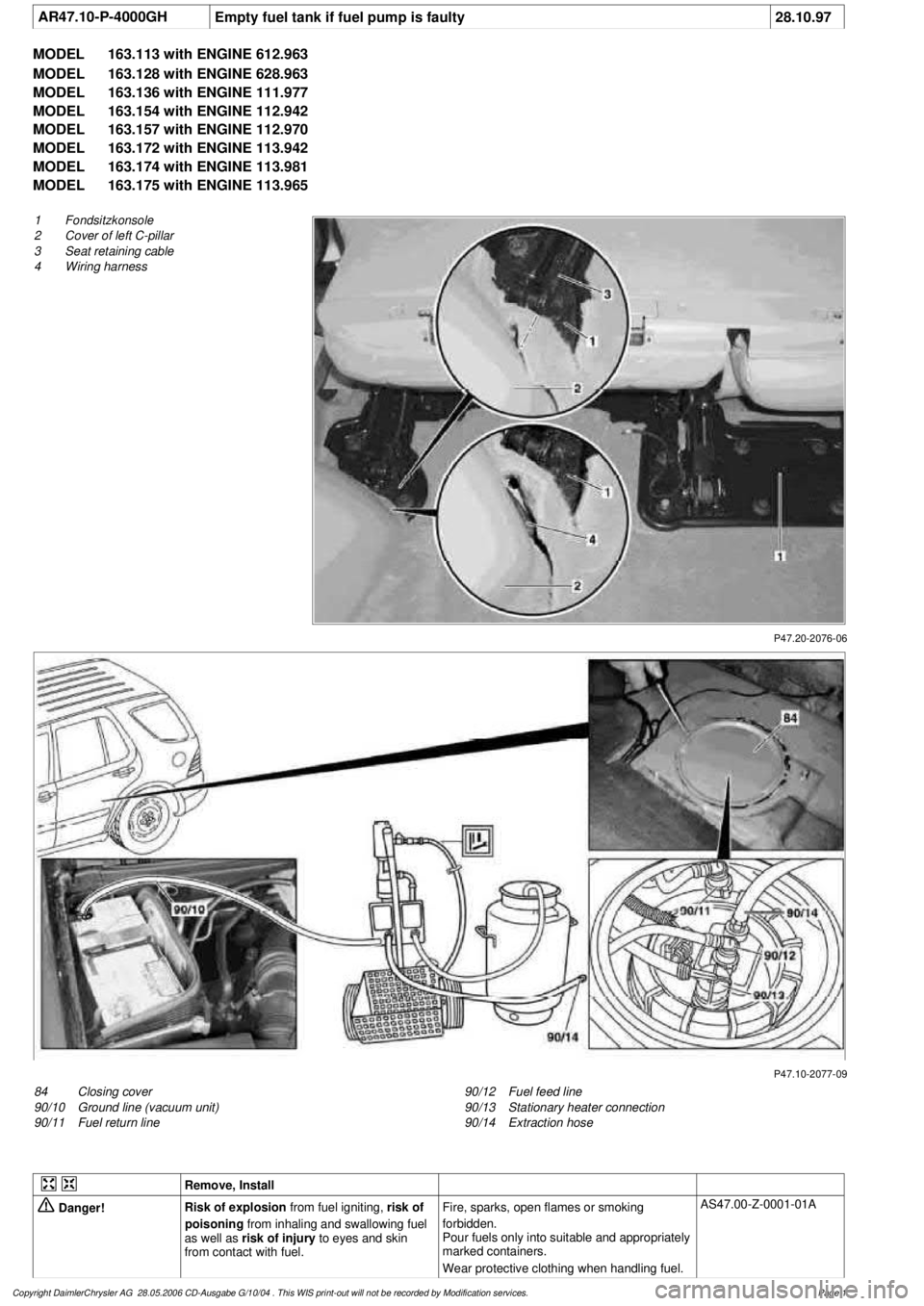
AR47.10-P-4000GH
Empty fuel tank if fuel pump is faulty
28.10.97
MODEL
163.113 with ENGINE 612.963
MODEL
163.128 with ENGINE 628.963
MODEL
163.136 with ENGINE 111.977
MODEL
163.154 with ENGINE 112.942
MODEL
163.157 with ENGINE 112.970
MODEL
163.172 with ENGINE 113.942
MODEL
163.174 with ENGINE 113.981
MODEL
163.175 with ENGINE 113.965
P47.20-2076-06
1
Fondsitzkonsole
2
Cover of left C-pillar
3
Seat retaining cable
4
Wiring harness
P47.10-2077-09
84
Closing cover
90/10
Ground line (vacuum unit)
90/11
Fuel return line
90/12
Fuel feed line
90/13
Stationary heater connection
90/14
Extraction hose
Remove, Install
Danger!
Risk of explosion
from fuel igniting,
risk of
poisoning
from inhaling and swallowing fuel
as well as
risk of injury
to eyes and skin
from contact with fuel.
Fire, sparks, open flames or smoking
forbidden.
Pour fuels only into suitable and appropriately
marked containers.
Wear protective clothing when handling fuel.
AS47.00-Z-0001-01A
Copyright DaimlerChrysler AG 28.05.2006 CD-Ausgabe G/10/04 . This WIS print-out will not be recorde
d by Modification services.
Page 1
Page 2230 of 4133

1.1
Unscrew bolts at rear of 2/3 seat bench and
raise rear of seat bench
Up to VIN A145272, X708318.
1.2
Remove covers at seat frame of 60% bench
seat
As of VIN A145273, X708319.
AR91.12-P-1100GH
Only remove the covers which are
identified in the document with A, D and E.
2.1
Fold 60% bench seat forward into footwell
As of VIN A145273, X708319. See
operator's manual.
3.1
Pull floor covering below rear seat mounting
bracket (1) of 60% seat forward
Carefully pull floor covering forward under
the seat console to prevent it from tearing.
As of VIN A145273, X708319.
4.1
Pull the floor covering forward under the front
corner of the left C-pillar cover (2)
Carefully pull the floor covering forward
under the cover to prevent it from tearing.
As of VIN A145273, X708319.
5
Cut into floor covering directly behind seat
retaining cable (3)
Ensure that the wiring harness (4) is not
damaged when cutting the floor covering.
As of VIN A145273, X708319. Broken
line marks the cut.
6
Fold floor mat back
Do not crease floor mat!
Fold floor mat back far enough to provide
access to cap (84) between body and fuel
pump.
7
Remove end cover (84) of body
Installation:
Replace cap and insert with
new sealing compound.
Cap (84) is sealed in with body sealer.
Heat with hot air blower to make it easier to
remove.
8
Seal fuel return line (90/11)
Pliers
*163589003700
9
Connect extraction hose (90/14) with adapter
hose to connection for fuel return line (90/11)
Extraction hose
*168589009000
Adapter hose
*163589009100
10
Connect ground cable (90/10) of extraction
pump ground terminal vehicle battery
Pumping out
11
Pump fuel out into safety container using
extraction pump
*BF47.10-P-1001-01A
*WH58.30-Z-1001-16A
12
Install in the reverse order
Fuel tank
Number
Designation
Models
163.113/
136/154/
172 up to
31.08.01
Models
163.113/
136/154/
172 as of
01.09.01
Models
163.157/
175
Model
163.128
Model
163.174
BF47.10-P-1001-01A
Fuel tank capacity
Total capacity
Liter
72838393
Reserve capacity
Liter
10121212
Copyright DaimlerChrysler AG 28.05.2006 CD-Ausgabe G/10/04 . This WIS print-out will not be recorde
d by Modification services.
Page 2
Page 2398 of 4133
Cylinder leakage
Fig. 31: Identifying Counterholder (112 589 00 40 00)
Commercially available tools
DISCONNECTING AND CONN ECTING ENGINE WIRING HARNESS - AR01.00-P-2410V
ENGINE 112.942 in MODEL 163.154
ENGINE 112.970 in MODEL 163.157
ENGINE 113.942 in MODEL 163.172
ENGINE 113.981 in MODEL 163.174
ENGINE 113.965 in MODEL 163.175
Shown on Model 163.154
order
NumberDesignationAll Engines
BE01.00-P-1001-02ZCylinder leakage
permissible loss total
indication%< or = 25
BE01.00-P-1002-02ZCylinder leakage
permissible losses at valves
and cylinder head gasket%< or = 10
BE01.00-P-1003-02ZCylinder leakage
permissible losses at
pistons and piston rings%< or = 20
NumberDesignation
WH58.30-Z-1015-05ACylinder leakage testing unit
2001 Mercedes-Benz ML320
1998-2005 ENGINE Complete engine - 163 Chassis
me
Saturday, October 02, 2010 3:17:56 PMPage 42 © 2006 Mitchell Repair Information Company, LLC.
Page 2399 of 4133
Fig. 32: Identifying Engine Wiring Harness - Shown On Model 163.154
Fig. 33: Identifying Ground Strap Of Engine/Body
- Shown On Model 163.154
Shown on Model 163.154
2001 Mercedes-Benz ML320
1998-2005 ENGINE Complete engine - 163 Chassis
me
Saturday, October 02, 2010 3:17:56 PMPage 43 © 2006 Mitchell Repair Information Company, LLC.