1997 MERCEDES-BENZ ML430 wiring
[x] Cancel search: wiringPage 2666 of 4133
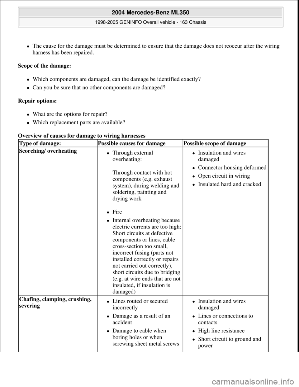
The cause for the damage must be determined to ensure that the damage does not reoccur after the wiring
harness has been repaired.
Scope of the damage:
Which components are damaged, can the damage be identified exactly?
Can you be sure that no other components are damaged?
Repair options:
What are the options for repair?
Which replacement parts are available?
Overview of causes for damage to wiring harnesses
Type of damage:Possible causes for damagePossible scope of damage
Scorching/ overheating Through external
overheating:
Through contact with hot
components (e.g. exhaust
system), during welding and
soldering, painting and
drying work
Fire
Internal overheating because
electric currents are too high:
Short circuits at defective
components or lines, cable
cross-section too small,
incorrect fusing (parts not
installed correctly or repairs
not carried out correctly),
short circuits due to bridging
(e.g. at wire ends that are not
insulated, if insulation is
damaged)
Insulation and wires
damaged
Connector housing deformed
Open circuit in wiring
Insulated hard and cracked
Chafing, clamping, crushing,
severing Lines routed or secured
incorrectly
Damage as a result of an
accident
Damage to cable when
boring holes or when
screwing sheet metal screws
Insulation and wires
damaged
Lines or connections to
contacts
High line resistance
Short circuit to ground and
power
2004 Mercedes-Benz ML350
1998-2005 GENINFO Overall vehicle - 163 Chassis
me
Saturday, October 02, 2010 3:47:44 PMPage 21 © 2006 Mitchell Repair Information Company, LLC.
Page 2667 of 4133
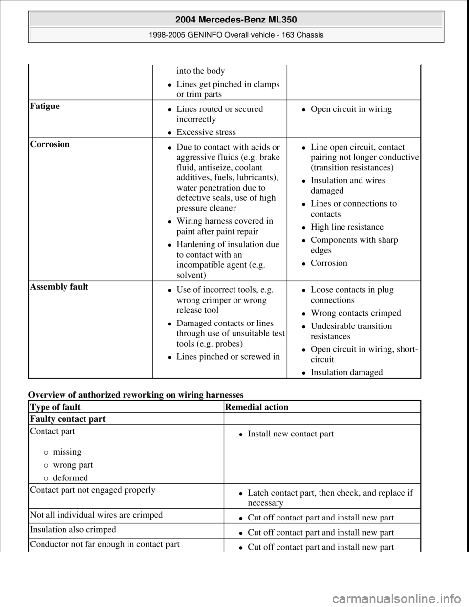
Overview of authorized reworking on wiring harnesses
into the body
Lines get pinched in clamps
or trim parts
Fatigue Lines routed or secured
incorrectly
Excessive stress
Open circuit in wiring
Corrosion Due to contact with acids or
aggressive fluids (e.g. brake
fluid, antiseize, coolant
additives, fuels, lubricants),
water penetration due to
defective seals, use of high
pressure cleaner
Wiring harness covered in
paint after paint repair
Hardening of insulation due
to contact with an
incompatible agent (e.g.
solvent)
Line open circuit, contact
pairing not longer conductive
(transition resistances)
Insulation and wires
damaged
Lines or connections to
contacts
High line resistance
Components with sharp
edges
Corrosion
Assembly fault Use of incorrect tools, e.g.
wrong crimper or wrong
release tool
Damaged contacts or lines
through use of unsuitable test
tools (e.g. probes)
Lines pinched or screwed in
Loose contacts in plug
connections
Wrong contacts crimped
Undesirable transition
resistances
Open circuit in wiring, short-
circuit
Insulation damaged
Type of faultRemedial action
Faulty contact part
Contact part
missing
wrong part
deformed
Install new contact part
Contact part not engaged properlyLatch contact part, then check, and replace if
necessary
Not all individual wires are crimpedCut off contact part and install new part
Insulation also crimpedCut off contact part and install new part
Conductor not far enough in contact partCut off contact part and install new part
2004 Mercedes-Benz ML350
1998-2005 GENINFO Overall vehicle - 163 Chassis
me
Saturday, October 02, 2010 3:47:44 PMPage 22 © 2006 Mitchell Repair Information Company, LLC.
Page 2672 of 4133
Plugs and couplings. with yellow, orange or red housing colors are reserved for safety and restraint systems
(SRS) and roll bars.
Observe the following when repairing couplings for squibs (SRS systems):
The repair area must be between 100 mm and 1000 mm behind the squib. Cables which have already been
repaired are provided with a yellow marking. This is to be applied retroactively to repair lines without color
marking.
Carry out the first repair as close to the plug as possible. In the case of subsequent repairs the old soldered
connectors should be removed and the new ones should be attached behind them, the wiring harness should be
replaced if necessary.
Before cutting through the lines it is absolutely essential to assign the lines to the corresponding pins in
accordance with the wiring diagram. Do not mix up the pin assignment.
The line colors of the repair kit may deviate from the original fitting
Screened lines and light plastic-sheathed cable must never be repaired
In general the following applies to cable repair:
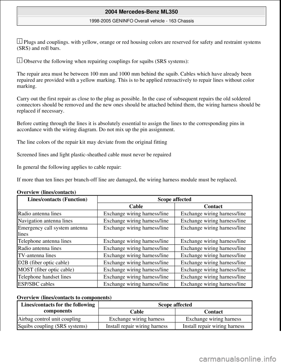
If more than ten lines per branch-off line are damaged, the wiring harness module must be replaced.
Overview (lines/contacts)
Overview (lines/contacts to components)
Lines/contacts (Function)Scope affected
CableContact
Radio antenna linesExchange wiring harness/lineExchange wiring harness/line
Navigation antenna linesExchange wiring harness/lineExchange wiring harness/line
Emergency call system antenna
linesExchange wiring harness/lineExchange wiring harness/line
Telephone antenna linesExchange wiring harness/lineExchange wiring harness/line
Radio antenna linesExchange wiring harness/lineExchange wiring harness/line
TV-antenna linesExchange wiring harness/lineExchange wiring harness/line
D2B (fiber optic cable)Exchange wiring harness/lineExchange wiring harness/line
MOST (fiber optic cable)Exchange wiring harness/lineExchange wiring harness/line
Telephone handset linesExchange wiring harness/lineExchange wiring harness/line
ESP/SBC cablesExchange wiring harness/lineExchange wiring harness/line
Lines/contacts for the following
componentsScope affected
CableContact
Airbag control unit couplingExchange wiring harnessExchange wiring harness
Squibs coupling (SRS systems)Install repair wiring harnessInstall repair wiring harness
2004 Mercedes-Benz ML350
1998-2005 GENINFO Overall vehicle - 163 Chassis
me
Saturday, October 02, 2010 3:47:44 PMPage 27 © 2006 Mitchell Repair Information Company, LLC.
Page 2678 of 4133
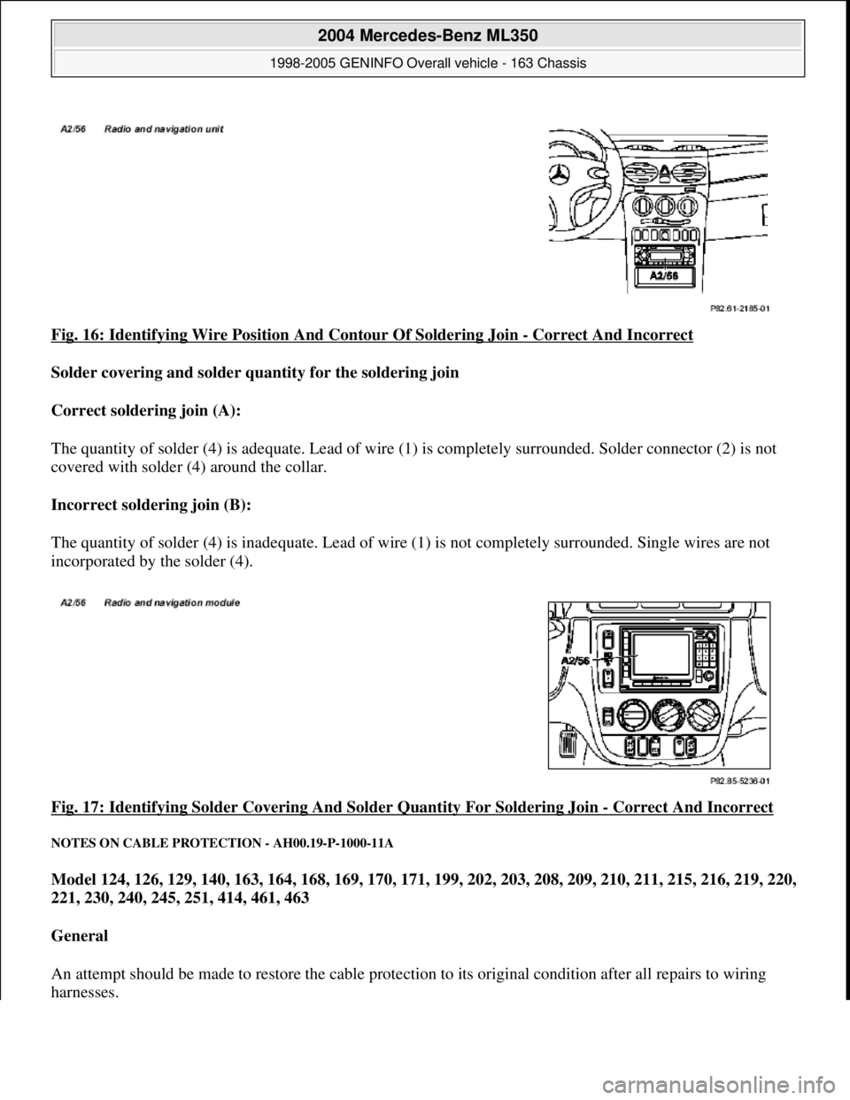
Fig. 16: Identifying Wire Position And Contour Of Soldering Join - Correct And Incorrect
Solder covering and solder quantity for the soldering join
Correct soldering join (A):
The quantity of solder (4) is adequate. Lead of wire (1) is completely surrounded. Solder connector (2) is not
covered with solder (4) around the collar.
Incorrect soldering join (B):
The quantity of solder (4) is inadequate. Lead of wi re (1) is not completely surrounded. Single wires are not
incorporated by the solder (4).
Fig. 17: Identifying Solder Covering A nd Solder Quantity For Soldering Join
- Correct And Incorrect
NOTES ON CABLE PROTECTION - AH00.19-P-1000-11A
Model 124, 126, 129, 140, 163, 164, 168, 169, 170, 171, 199, 202, 203, 208, 209, 210, 211, 215, 216, 219, 220,
221, 230, 240, 245, 251, 414, 461, 463
General
An attempt should be made to restor e the cable protection to its original condition after all repairs to wiring
harnesses.
2004 Mercedes-Benz ML350
1998-2005 GENINFO Overall vehicle - 163 Chassis
me
Saturday, October 02, 2010 3:47:44 PMPage 33 © 2006 Mitchell Repair Information Company, LLC.
Page 2891 of 4133
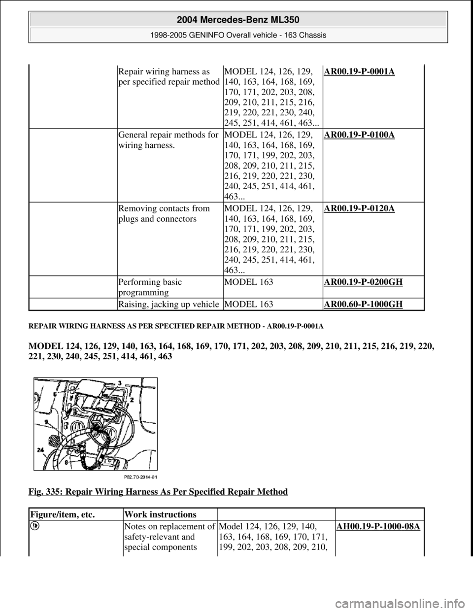
REPAIR WIRING HARNESS AS PER SPECIFIED REPAIR METHOD - AR00.19-P-0001A
MODEL 124, 126, 129, 140, 163, 164, 168, 169, 170, 171, 202, 203, 208, 209, 210, 211, 215, 216, 219, 220,
221, 230, 240, 245, 251, 414, 461, 463
Fig. 335: Repair Wiring Harness As Per Specified Repair Method
Repair wiring harness as
per specified repair methodMODEL 124, 126, 129,
140, 163, 164, 168, 169,
170, 171, 202, 203, 208,
209, 210, 211, 215, 216,
219, 220, 221, 230, 240,
245, 251, 414, 461, 463...AR00.19-P-0001A
General repair methods for
wiring harness.MODEL 124, 126, 129,
140, 163, 164, 168, 169,
170, 171, 199, 202, 203,
208, 209, 210, 211, 215,
216, 219, 220, 221, 230,
240, 245, 251, 414, 461,
463...AR00.19-P-0100A
Removing contacts from
plugs and connectorsMODEL 124, 126, 129,
140, 163, 164, 168, 169,
170, 171, 199, 202, 203,
208, 209, 210, 211, 215,
216, 219, 220, 221, 230,
240, 245, 251, 414, 461,
463...AR00.19-P-0120A
Performing basic
programmingMODEL 163AR00.19-P-0200GH
Raising, jacking up vehicleMODEL 163AR00.60-P-1000GH
Figure/item, etc.Work instructions
Notes on replacement of
safety-relevant and
special componentsModel 124, 126, 129, 140,
163, 164, 168, 169, 170, 171,
199, 202, 203, 208, 209, 210, AH00.19-P-1000-08A
2004 Mercedes-Benz ML350
1998-2005 GENINFO Overall vehicle - 163 Chassis
me
Saturday, October 02, 2010 3:47:48 PMPage 246 © 2006 Mitchell Repair Information Company, LLC.
Page 2892 of 4133
211, 215, 216, 219, 220, 221,
230, 240, 245, 251, 414, 461
as of 1.4.94, 463
Assessment of damage
in wiring harnessesModel 124, 126, 129, 140,
163, 164, 168, 169, 170, 171,
199, 202, 203, 208, 209, 210,
211, 215, 216, 219, 220, 221,
230, 240, 245, 251, 414, 461,
463AH00.19-P-1000-05A
Assessment of airbag
and belt tensioner units
in accident vehiclesModel 129, 202 up to 30.6.93
Model 124, 126, 140AH91.00-P-0006-01A
Assessment of airbag
and belt tensioner units
in accident vehiclesModel 129 as of 1.7.93, 163,
164, 168, 169, 170, 171, 199,
202 as of 1.7.93, 203, 208,
209, 210, 211, 215, 216, 219,
220, 221, 230, 240, 245, 251,
414, 461 as of 1.4.94, 463,
638, 901, 902, 903, 904, 905,
906, WD1, WD2, WD3, WD6,
WD7, XD1, XD2, XD3, XD4,
XD5, XD6, XD7, YD1, YD2,
YD3, YD4, YD5, YD6, YD7AH91.00-P-0006-01B
Notes regarding plug
connections AH00.19-P-1000-06A
Advantages of repairing
wiring harnesses AH00.19-P-1000-03A
Repair methods for
wiring harnesses AH00.19-P-1000-04A
Repair supplemental
restraint system (SRS)
squib wiring harnessModel 124, 129, 140, 163,
164, 168, 169, 170, 171, 202,
203, 208, 209, 210, 211, 215,
216, 219, 220, 221, 230, 240,
245, 251, 414, 461 as of
1.4.94, 463
Model 126 with code 291
Airbag for driver and front
passenger (for front passenger
only if driver airbag standard)
Model 126 with code 442
Airbag in steering wheelAR54.18-P-0600A
Repairing wiring
harnessModel 168.031 ## up to
180747 with engine 166.940
Engine wiring harness at body
side
Model 168.033 ## up to AR54.18-P-0100GF
2004 Mercedes-Benz ML350
1998-2005 GENINFO Overall vehicle - 163 Chassis
me
Saturday, October 02, 2010 3:47:48 PMPage 247 © 2006 Mitchell Repair Information Company, LLC.
Page 2893 of 4133
180747 with engine 166.960
Engine wiring harness at body
side
Repairing wiring
harnessModel 168.007 with engine
668.941
Engine wiring harness at body
side
Model 168.008 with engine
668.940
Engine wiring harness at body
sideAR54.18-P-0100GD
Repairing wiring
harnessModel 168.007 with engine
668.941
Engine wiring harness
Model 168.008 with engine
668.940
Engine wiring harnessAR54.18-P-0100GC
Install left front repair
wiring harnessModel
168.007/008/031/032/033
Only vehicles with one-piece
wiring harnessAR54.18-P-0700GC
Install right front repair
wiring harnessModel
168.007/008/031/032/033
Only vehicles with one-piece
wiring harnessAR54.18-P-0701GC
Install left rear repair
wiring harnessModel
168.007/008/031/032/033
Only vehicles with one-piece
wiring harnessAR54.18-P-0702GC
Install right rear repair
wiring harnessModel
168.007/008/031/032/033
Only vehicles with one-piece
wiring harnessAR54.18-P-0703GC
General repair method
for wiring harness. AR00.19-P-0100A
Checking wiring harness AR54.18-P-0600-01A
Electrical connection setFig. 336
126-pin socket boxFig. 337
2004 Mercedes-Benz ML350
1998-2005 GENINFO Overall vehicle - 163 Chassis
me
Saturday, October 02, 2010 3:47:48 PMPage 248 © 2006 Mitchell Repair Information Company, LLC.
Page 2894 of 4133
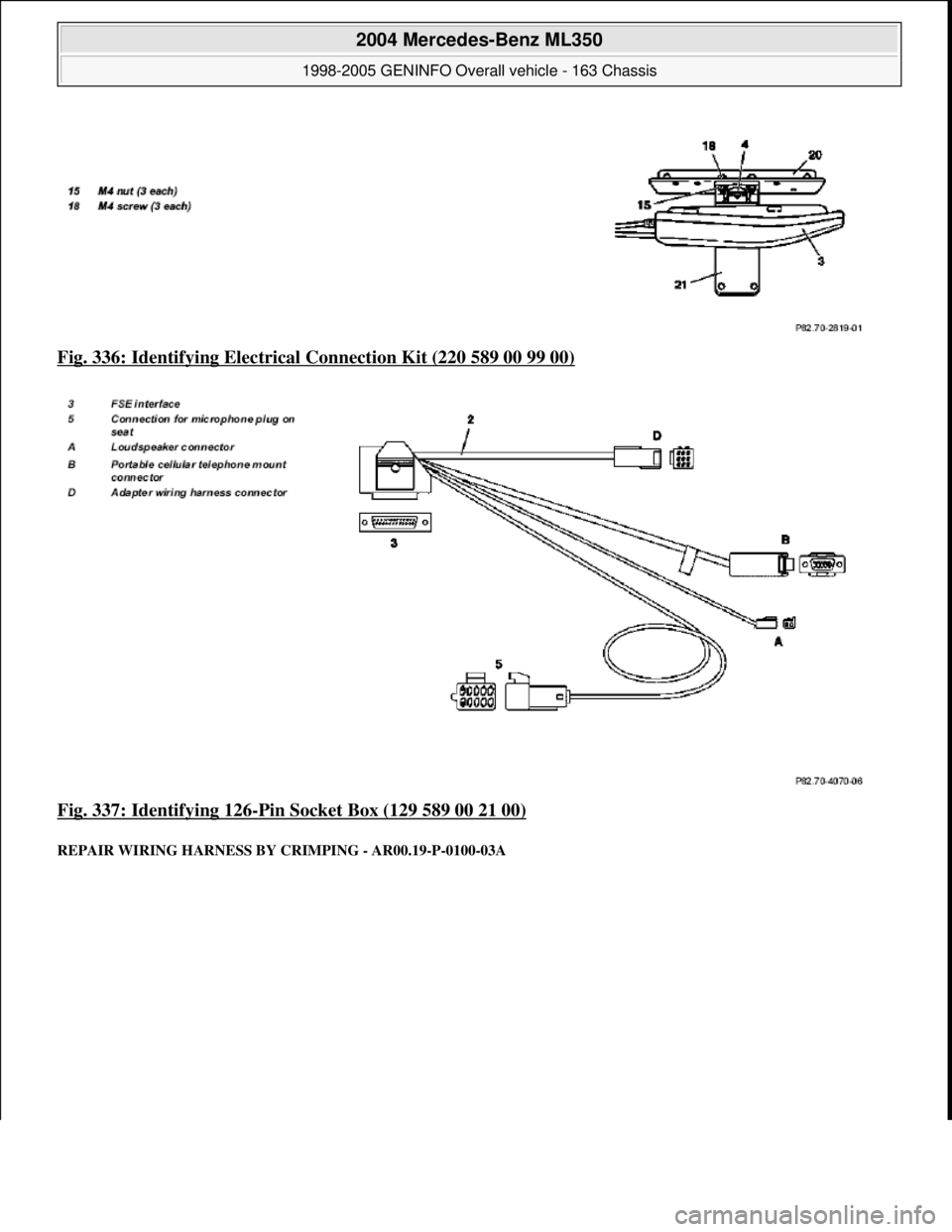
Fig. 336: Identifying Electrical Connection Kit (220 589 00 99 00)
Fig. 337: Identifying 126
-Pin Socket Box (129 589 00 21 00)
REPAIR WIRING HA RNESS BY CRIMPING - AR00.19-P-0100-03A
2004 Mercedes-Benz ML350
1998-2005 GENINFO Overall vehicle - 163 Chassis
me
Saturday, October 02, 2010 3:47:48 PMPage 249 © 2006 Mitchell Repair Information Company, LLC.