1997 MERCEDES-BENZ ML430 wiring
[x] Cancel search: wiringPage 2401 of 4133
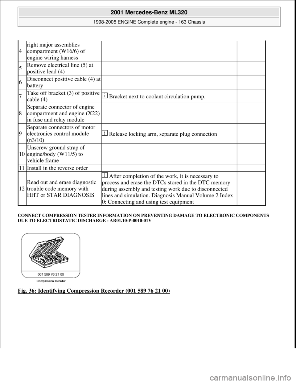
CONNECT COMPRESSION TESTER INFORMATION ON PR EVENTING DAMAGE TO ELECTRONIC COMPONENTS
DUE TO ELECTROSTATIC DI SCHARGE - AR01.10-P-0010-01V
Fig. 36: Identifying Compression Recorder (001 589 76 21 00)
4
right major assemblies
compartment (W16/6) of
engine wiring harness
5Remove electrical line (5) at
positive lead (4)
6Disconnect positive cable (4) at
battery
7Take off bracket (3) of positive
cable (4) Bracket next to coolant circulation pump.
8
Separate connector of engine
compartment and engine (X22)
in fuse and relay module
9
Separate connectors of motor
electronics control module
(n3/10)
Release locking arm, separate plug connection
10
Unscrew ground strap of
engine/body (W11/5) to
vehicle frame
11Install in the reverse order
12
Read out and erase diagnostic
trouble code memory with
HHT or STAR DIAGNOSIS
After completion of the work, it is necessary to
process and erase the DTCs stored in the DTC memory
during assembly and testing work due to disconnected
lines and simulation. Diagnosis Manual Volume 2 Index
0: Connecting and using test equipment
2001 Mercedes-Benz ML320
1998-2005 ENGINE Complete engine - 163 Chassis
me
Saturday, October 02, 2010 3:17:56 PMPage 45 © 2006 Mitchell Repair Information Company, LLC.
Page 2412 of 4133
22Disconnect engine
wiring harness AR01.00-P-
2410V
23Remove poly V-belt
(3) Installation: Lock tensioning device with a
drift or pin (diameter 5 mm).
Model 163.154/157/172.AR13.22-P-
1202B
Model 163.174/175.AR13.22-P-
1202BA
24Disconnect
connector from A/C
compressor (10)
25Unbolt AC
compressor (10)
from timing case
cover Attach AC compressor at side in bottom of
engine compartment with lines connected.
*BA83.55-P-
1001-01A
26.1Remove left inner
fender (24) Only engine 113.942 /965 /981.AR88.10-P-
1300GH
27.1Remove shield (25) Only engine 113.942 /965 /981.
28Detach exhaust
system (11) at
exhaust manifold Installation: On vehicles with engine
damage check exhaust sy stem for chips before
assembly and remove any chips present to
prevent later damage
*BA14.10-P-
1002-01B
29Detach exhaust
bracket (12)Support exhaust system for this step.
Installation: Install new nuts.
30Unbolt torque
converter (20) from
starter ring gear(21) Installation: The mounting points (arrows,
black) of the torque converter (20) must be
flush with the three recesses (arrows, white) in
the starting ring gear (21).
*BA27.20-P-
1002-01C
31Disconnect left O2
sensor connector
before TWC
(G3/3x1) and right
O2 sensor connector
before TWC
(G3/4x1) from
transmission Remove cable ties!
32Unscrew starter Do not disconnect electric cables.
*BA15.30-P-
1003-01A
33Unscrew bolts at
transmission bell Engine 112.942/ 970.
Do not unscrew two top bolts at transmission
bell.
Engine 113.942 /965/ 981. Do not unscrew
2001 Mercedes-Benz ML320
1998-2005 ENGINE Complete engine - 163 Chassis
me
Saturday, October 02, 2010 3:17:56 PMPage 56 © 2006 Mitchell Repair Information Company, LLC.
Page 2550 of 4133
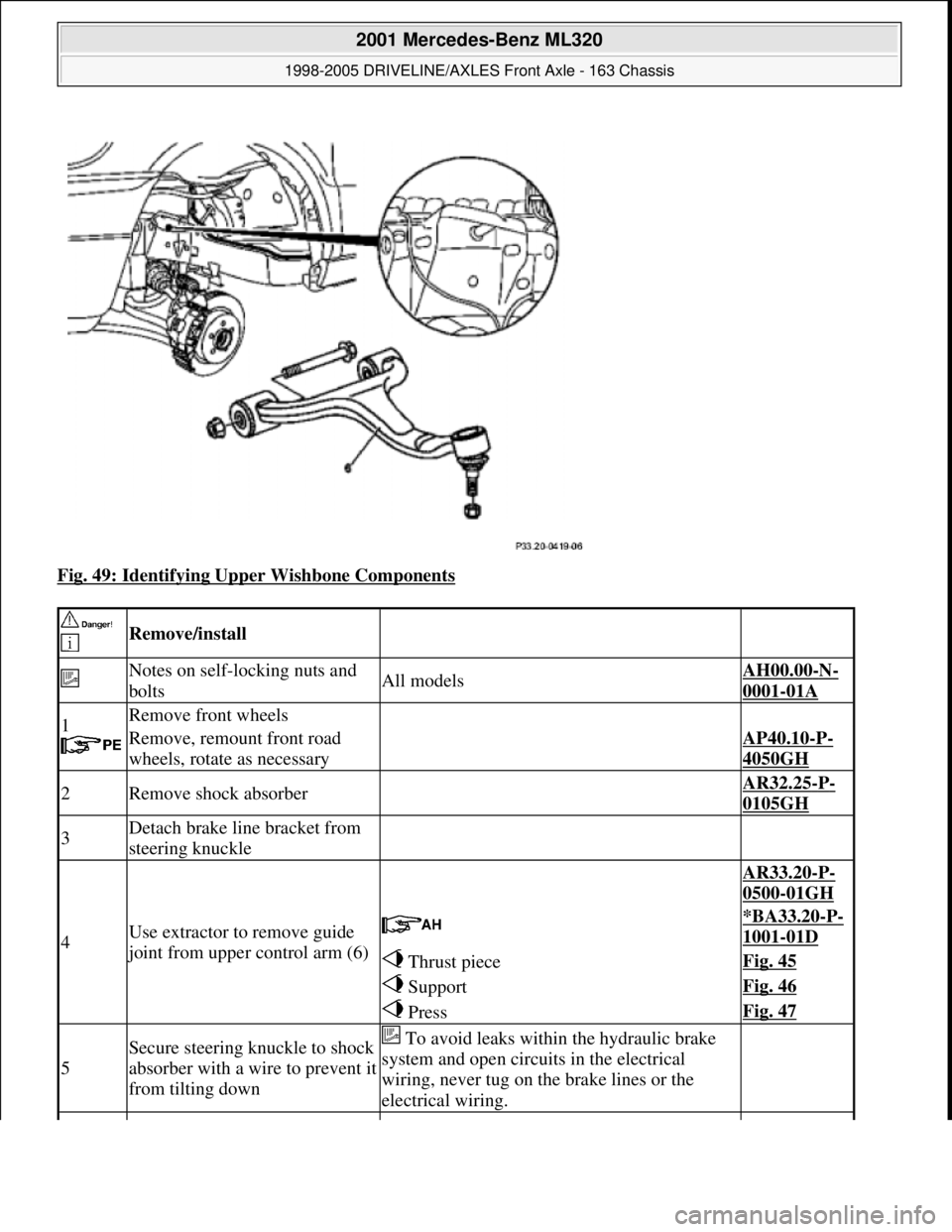
Fig. 49: Identifying Upper Wishbone Components
Remove/install
Notes on self-locking nuts and
boltsAll modelsAH00.00-N-
0001-01A
1
Remove front wheels
Remove, remount front road
wheels, rotate as necessaryAP40.10-P-
4050GH
2Remove shock absorber AR32.25-P-
0105GH
3Detach brake line bracket from
steering knuckle
4Use extractor to remove guide
joint from upper control arm (6)
AR33.20-P-
0500-01GH
*BA33.20-P-
1001-01D
Thrust pieceFig. 45
SupportFig. 46
PressFig. 47
5
Secure steering knuckle to shock
absorber with a wire to prevent it
from tilting down To avoid leaks within the hydraulic brake
system and open circuits in the electrical
wiring, never tug on the brake lines or the
electrical wiring.
2001 Mercedes-Benz ML320
1998-2005 DRIVELINE/AXLES Front Axle - 163 Chassis
me
Saturday, October 02, 2010 3:38:22 PMPage 31 © 2006 Mitchell Repair Information Company, LLC.
Page 2596 of 4133
AR47.10-P-7000GI
Remove/install fuel level sensor
21.2.01
MODEL
163.113 with ENGINE 612.963
MODEL
163.128 with ENGINE 628.963
P47.10-2128-06
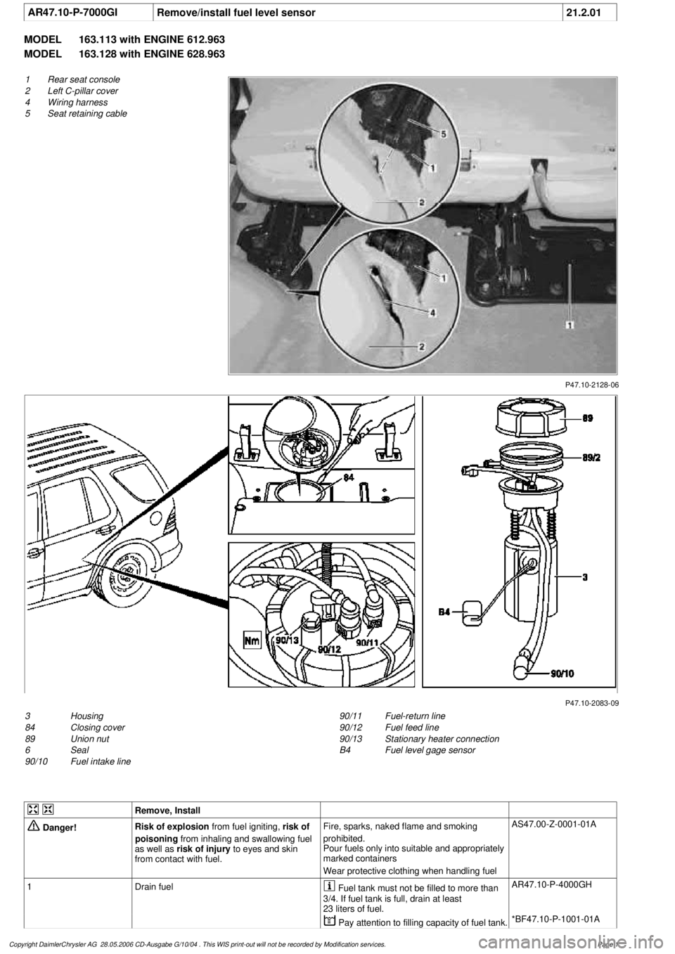
1
Rear seat console
2
Left C-pillar cover
4
Wiring harness
5
Seat retaining cable
P47.10-2083-09
3
Housing
84
Closing cover
89
Union nut
6
Seal
90/10
Fuel intake line
90/11
Fuel-return line
90/12
Fuel feed line
90/13
Stationary heater connection
B4
Fuel level gage sensor
Remove, Install
Danger!
Risk of explosion
from fuel igniting,
risk of
poisoning
from inhaling and swallowing fuel
as well as
risk of injury
to eyes and skin
from contact with fuel.
Fire, sparks, naked flame and smoking
prohibited.
Pour fuels only into suitable and appropriately
marked containers
Wear protective clothing when handling fuel
AS47.00-Z-0001-01A
1
Drain fuel
Fuel tank must not be filled to more than
3/4. If fuel tank is full, drain at least
23 liters of fuel.
AR47.10-P-4000GH
Pay attention to filling capacity of fuel tank.
*BF47.10-P-1001-01A
Copyright DaimlerChrysler AG 28.05.2006 CD-Ausgabe G/10/04 . This WIS print-out will not be recorde
d by Modification services.
Page 1
Page 2597 of 4133

2
Remove covers at seat frame of 60% bench
seat
As of VIN A145273, X708319.
AR91.12-P-1100GH
Only remove the covers which are
identified in the document with A, D and E.
3
Fold 60% bench seat forward into footwell
As of VIN A145273, X708319. See
operator's manual.
4
Pull floor covering below rear seat mounting
bracket (1) of 60% seat forward
Ensure that the floor covering is not torn
when pulled forward.
As of VIN A145273, X708319.
5
Pull floor covering below front corner of trim
panel of C-pillar (2) forward
Ensure that the floor covering is not torn
when pulled forward.
As of VIN A145273, X708319.
6
Cut into floor covering directly behind seat
retaining cable (5)
Ensure that the wiring harness (4) is not
damaged when cutting into floor covering.
As of VIN A145273, X708319. broken line
marks cut-in.
7
Turn back floor covering to gain access to
cap (84)
Do not kink floor covering.
8
Remove cap (84)
Cap (84) is sealed in with body sealer.
Heat with hot air blower to make it easier to
remove.
Installation:
Replace cap and install with
new sealing compound.
9
Detach fuel feed line (90/12) and fuel return
line (90/11) and, if fitted, the fuel line at
connection (90/13)
Do not kink the fuel lines.
If no stationary heater is fitted to vehicle,
do not remove connection (90/13) otherwise
housing will be damaged.
*163589003700
10
Remove nut (89)
*163589010700
*BA47.20-P-1006-01B
11
Remove housing (3)
Fuel lever sensor and housing are a
single part and cannot be removed separately.
Installation:
Re-install nut (89) together
with seal (89/2).
Apply a thin film of oil to seal.
12
Install in the reverse order
Fuel pump
Number
Designation
Engine 612Engine 628
BA47.20-P-1006-01B
Union nut for fuel tank sensor on fuel
tank
Nm
6565
Fuel tank
Number
Designation
Models
163.113/
136/154/
172 up to
31.08.01
Model
163.113/
136/154/
172 as of
01.09.01
Model
163.157/
175
Model
163.128
BF47.10-P-1001-01A
Fuel tank capacity
Total capacity
Liter
728383
Reserve capacity
Liter
101212
Copyright DaimlerChrysler AG 28.05.2006 CD-Ausgabe G/10/04 . This WIS print-out will not be recorde
d by Modification services.
Page 2
Page 2600 of 4133
AR47.10-P-4000GH
Empty fuel tank if fuel pump is faulty
28.10.97
MODEL
163.113 with ENGINE 612.963
MODEL
163.128 with ENGINE 628.963
MODEL
163.136 with ENGINE 111.977
MODEL
163.154 with ENGINE 112.942
MODEL
163.157 with ENGINE 112.970
MODEL
163.172 with ENGINE 113.942
MODEL
163.174 with ENGINE 113.981
MODEL
163.175 with ENGINE 113.965
P47.20-2076-06
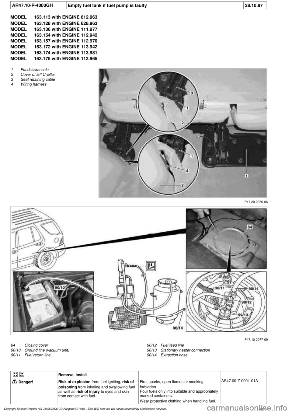
1
Fondsitzkonsole
2
Cover of left C-pillar
3
Seat retaining cable
4
Wiring harness
P47.10-2077-09
84
Closing cover
90/10
Ground line (vacuum unit)
90/11
Fuel return line
90/12
Fuel feed line
90/13
Stationary heater connection
90/14
Extraction hose
Remove, Install
Danger!
Risk of explosion
from fuel igniting,
risk of
poisoning
from inhaling and swallowing fuel
as well as
risk of injury
to eyes and skin
from contact with fuel.
Fire, sparks, open flames or smoking
forbidden.
Pour fuels only into suitable and appropriately
marked containers.
Wear protective clothing when handling fuel.
AS47.00-Z-0001-01A
Copyright DaimlerChrysler AG 28.05.2006 CD-Ausgabe G/10/04 . This WIS print-out will not be recorde
d by Modification services.
Page 1
Page 2601 of 4133

1.1
Unscrew bolts at rear of 2/3 seat bench and
raise rear of seat bench
Up to VIN A145272, X708318.
1.2
Remove covers at seat frame of 60% bench
seat
As of VIN A145273, X708319.
AR91.12-P-1100GH
Only remove the covers which are
identified in the document with A, D and E.
2.1
Fold 60% bench seat forward into footwell
As of VIN A145273, X708319. See
operator's manual.
3.1
Pull floor covering below rear seat mounting
bracket (1) of 60% seat forward
Carefully pull floor covering forward under
the seat console to prevent it from tearing.
As of VIN A145273, X708319.
4.1
Pull the floor covering forward under the front
corner of the left C-pillar cover (2)
Carefully pull the floor covering forward
under the cover to prevent it from tearing.
As of VIN A145273, X708319.
5
Cut into floor covering directly behind seat
retaining cable (3)
Ensure that the wiring harness (4) is not
damaged when cutting the floor covering.
As of VIN A145273, X708319. Broken
line marks the cut.
6
Fold floor mat back
Do not crease floor mat!
Fold floor mat back far enough to provide
access to cap (84) between body and fuel
pump.
7
Remove end cover (84) of body
Installation:
Replace cap and insert with
new sealing compound.
Cap (84) is sealed in with body sealer.
Heat with hot air blower to make it easier to
remove.
8
Seal fuel return line (90/11)
Pliers
*163589003700
9
Connect extraction hose (90/14) with adapter
hose to connection for fuel return line (90/11)
Extraction hose
*168589009000
Adapter hose
*163589009100
10
Connect ground cable (90/10) of extraction
pump ground terminal vehicle battery
Pumping out
11
Pump fuel out into safety container using
extraction pump
*BF47.10-P-1001-01A
*WH58.30-Z-1001-16A
12
Install in the reverse order
Fuel tank
Number
Designation
Models
163.113/
136/154/
172 up to
31.08.01
Models
163.113/
136/154/
172 as of
01.09.01
Models
163.157/
175
Model
163.128
Model
163.174
BF47.10-P-1001-01A
Fuel tank capacity
Total capacity
Liter
72838393
Reserve capacity
Liter
10121212
Copyright DaimlerChrysler AG 28.05.2006 CD-Ausgabe G/10/04 . This WIS print-out will not be recorde
d by Modification services.
Page 2
Page 2613 of 4133
AR47.30-P-8200GH
Remove/install fuel vapor expansion reservoir
13.3.01
MODEL
163.113 #A as of 289565,
163.113 #X as of 754620,
163.154 #A as of 289565,
163.154 #X as of 754620,
163.128 /157 /175
P47.30-2044-01
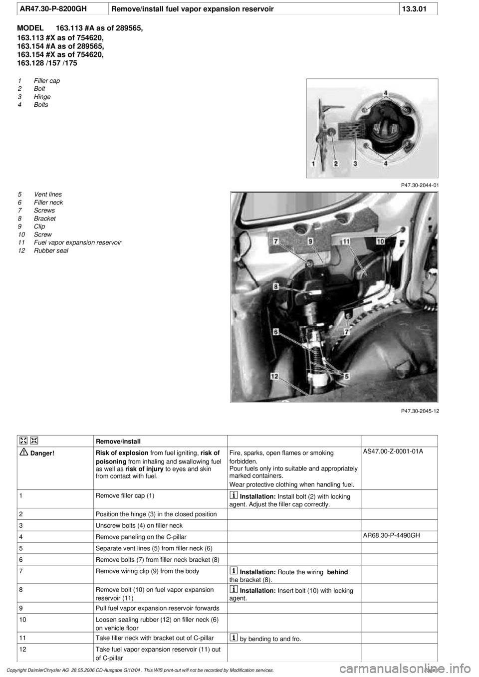
1
Filler cap
2
Bolt
3
Hinge
4
Bolts
P47.30-2045-12
5
Vent lines
6
Filler neck
7
Screws
8
Bracket
9
Clip
10
Screw
11
Fuel vapor expansion reservoir
12
Rubber seal
Remove/install
Danger!
Risk of explosion
from fuel igniting,
risk of
poisoning
from inhaling and swallowing fuel
as well as
risk of injury
to eyes and skin
from contact with fuel.
Fire, sparks, open flames or smoking
forbidden.
Pour fuels only into suitable and appropriately
marked containers.
Wear protective clothing when handling fuel.
AS47.00-Z-0001-01A
1
Remove filler cap (1)
Installation:
Install bolt (2) with locking
agent. Adjust the filler cap correctly.
2
Position the hinge (3) in the closed position
3
Unscrew bolts (4) on filler neck
4
Remove paneling on the C-pillar
AR68.30-P-4490GH
5
Separate vent lines (5) from filler neck (6)
6
Remove bolts (7) from filler neck bracket (8)
7
Remove wiring clip (9) from the body
Installation:
Route the wiring
behind
the bracket (8).
8
Remove bolt (10) on fuel vapor expansion
reservoir (11)
Installation:
Insert bolt (10) with locking
agent.
9
Pull fuel vapor expansion reservoir forwards
10
Loosen sealing rubber (12) on filler neck (6)
on vehicle floor
11
Take filler neck with bracket out of C-pillar
by bending to and fro.
12
Take fuel vapor expansion reservoir (11) out
of C-pillar
Copyright DaimlerChrysler AG 28.05.2006 CD-Ausgabe G/10/04 . This WIS print-out will not be recorde
d by Modification services.
Page 1