Page 1932 of 4133

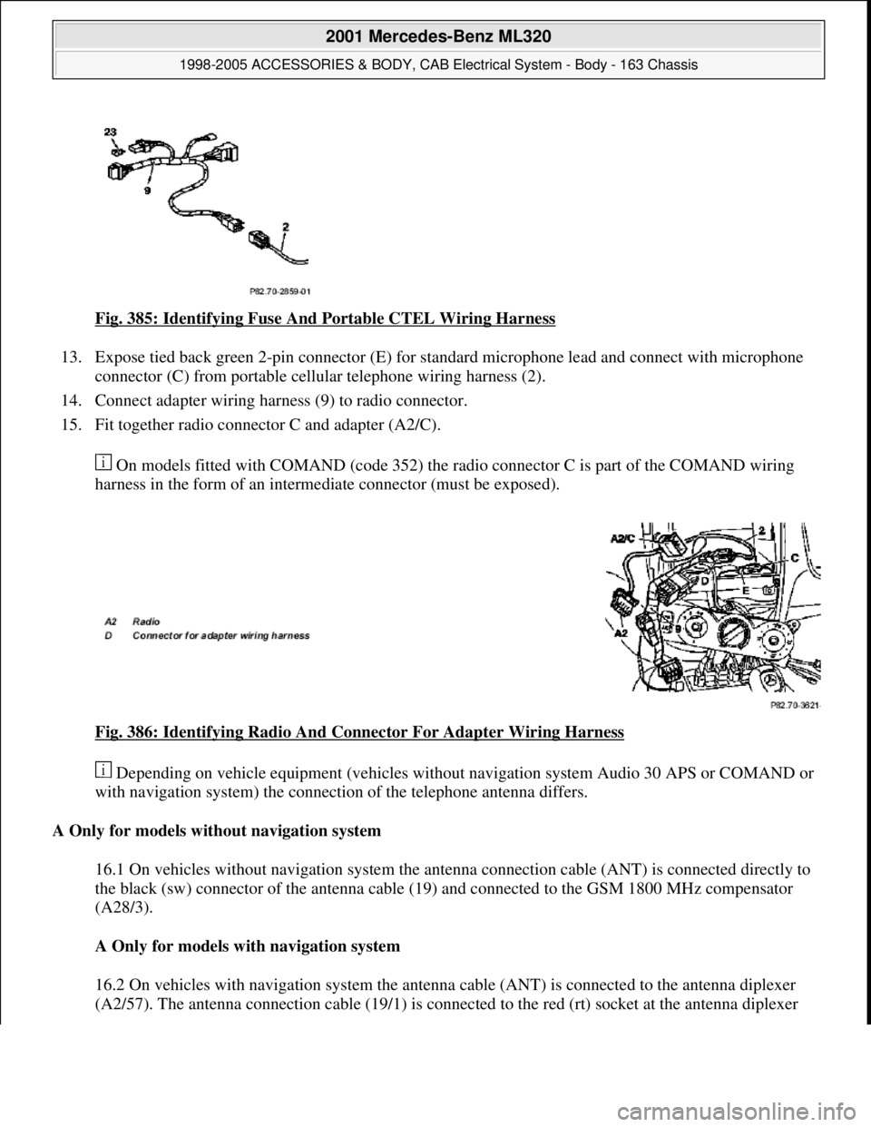
Fig. 385: Identifying Fuse And Portable CTEL Wiring Harness
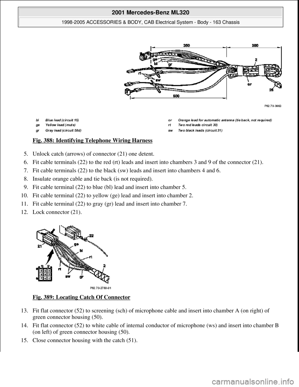
13. Expose tied back green 2-pin connector (E) for standard microphone lead and connect with microphone
connector (C) from portable cellular telephone wiring harness (2).
14. Connect adapter wiring harness (9) to radio connector.
15. Fit together radio connector C and adapter (A2/C).
On models fitted with COMAND (code 352) the radio connector C is part of the COMAND wiring
harness in the form of an intermediate connector (must be exposed).
Fig. 386: Identifying Radio And Connector For Adapter Wiring Harness
Depending on vehicle equipment (vehicles without navigation system Audio 30 APS or COMAND or
with navigation system) the connection of the telephone antenna differs.
A Only for models without navigation system
16.1 On vehicles without navigation system the antenna connection cable (ANT) is connected directly to
the black (sw) connector of the antenna cable (19) and connected to the GSM 1800 MHz compensator
(A28/3).
A Only for models with navigation system
16.2 On vehicles with navigation system the antenna cable (ANT) is connected to the antenna diplexer
(A2/57). The antenna connection cable (19/1) is connected to the red (rt) socket at the antenna diplexer
2001 Mercedes-Benz ML320
1998-2005 ACCESSORIES & BODY, CAB Electrical System - Body - 163 Chassis
me
Saturday, October 02, 2010 3:30:13 PMPage 437 © 2006 Mitchell Repair Information Company, LLC.
Page 1933 of 4133
(A2/57) and to the GSM 1800 MHz compensator (A28/3).
Fig. 387: Identifying
17 The GSM 1800 MHz compensator is connected to the antenna cable (17) at the mount for the portable
CTEL (1).
RETROFIT WIRING HARNESS - AZ82.70-P-0001-04GHH
Model 163 as of 1.9.00 for Nokia 6090 fixed installation cellular telephone
1. Prepare telephone wiring harness (2) as shown in figure.
2. Tie back audio line-out cable with 4-pin connector (25) (is not required).
3. Expose two red (rt) and two black (sw) cables.
4. Cut off the two 2-pin connector housings of microphone speaker to the size of 350 mm as shown in figure
and expose the leads (the are provided with a new connector housin
g).
2001 Mercedes-Benz ML320
1998-2005 ACCESSORIES & BODY, CAB Electrical System - Body - 163 Chassis
me
Saturday, October 02, 2010 3:30:13 PMPage 438 © 2006 Mitchell Repair Information Company, LLC.
Page 1934 of 4133

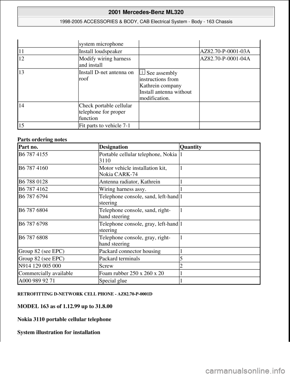
Fig. 388: Identifying Telephone Wiring Harness
5. Unlock catch (arrows) of connector (21) one detent.
6. Fit cable terminals (22) to the red (rt) leads and insert into chambers 3 and 9 of the connector (21).
7. Fit cable terminals (22) to the black (sw) leads and insert into chambers 4 and 6.
8. Insulate orange cable and tie back (is not required).
9. Fit cable terminal (22) to blue (bl) lead and insert into chamber 5.
10. Fit cable terminal (22) to yellow (ge) lead and insert into chamber 2.
11. Fit cable terminal (22) to gray (gr) lead and insert into chamber 7.
12. Lock connector (21).
Fig. 389: Locating Catch Of Connector
13. Fit flat connector (52) to screening (sch) of microphone cable and insert into chamber A (on right) of
green connector housing (50).
14. Fit flat connector (52) to white cable of internal conductor of microphone (ws) and insert into chamber B
(on left) of green connector housing (50).
15. Close connector housin
g with the catch (51).
2001 Mercedes-Benz ML320
1998-2005 ACCESSORIES & BODY, CAB Electrical System - Body - 163 Chassis
me
Saturday, October 02, 2010 3:30:13 PMPage 439 © 2006 Mitchell Repair Information Company, LLC.
Page 1935 of 4133
Fig. 390: Identifying Flat Connect or, Connector Housing & Catch
16. Fit flat receptacle (57) to the back cable (sw) and insert into chamber A (on left) of the black receptacle
housing (55).
17. Fit flat receptacle (57) to the black/white cable (sw/ ws) and insert into chamber B (on right) of the black
receptacle housing (55).
18. Close receptacle housing (55) with catch (56).
Fig. 391: Identifying Flat Recept acle, Receptacle Housing & Catch
19. Insert wiring harness (2) into instrument panel working from the glove compartment.
The tie
d-back part must be placed belo w the strut (arrows) at the glove compartment.
2001 Mercedes-Benz ML320
1998-2005 ACCESSORIES & BODY, CAB Electr ical System - Body - 163 Chassis
me
Saturday, October 02, 2010 3:30:14 PMPage 440 © 2006 Mitchell Repair Information Company, LLC.
Page 1936 of 4133
Fig. 392: Locating Wiring Harness
20. Connect telephone wiring harness (2) to adapter wiring harness (9).
21. Check fuse (23) (a 10A fuse should be present).
Fig. 393: Identifying Telephone Wiring Harness To Adapter Wiring Harness Connection & Fuse
22. Connect adapter wiring harness (9) to radio wiring harness and insert into radio slot.
23. Place microphone cable of telephone wirin
g harness (2) into radio slot.
2001 Mercedes-Benz ML320
1998-2005 ACCESSORIES & BODY, CAB Electr ical System - Body - 163 Chassis
me
Saturday, October 02, 2010 3:30:14 PMPage 441 © 2006 Mitchell Repair Information Company, LLC.
Page 1937 of 4133
Fig. 394: Identifying Telephone & Adapter Wiring Harnesses
24. Route connection cable of telephone wiring harness (2) to telephone handset in cockpit as shown in
figure.
Fig. 395: Identifying Telephone Wiring Ha rness & Telephone Handset In Cockpit
RETROFIT D-NETWORK CELL PHONE - AZ82.70-P-0001A
MODEL 163 up to 30.11.99
Nokia 3110 portable cellular telephone
System illustration for installation
2001 Mercedes-Benz ML320
1998-2005 ACCESSORIES & BODY, CAB Electr ical System - Body - 163 Chassis
me
Saturday, October 02, 2010 3:30:14 PMPage 442 © 2006 Mitchell Repair Information Company, LLC.
Page 1939 of 4133

Parts ordering notes
RETROFITTING D-NETWORK CELL PHONE - AZ82.70-P-0001D
MODEL 163 as of 1.12.99 up to 31.8.00
Nokia 3110 portable cellular telephone
System illustration for installation
system microphone
11Install loudspeaker AZ82.70-P-0001-03A
12Modify wiring harness
and install AZ82.70-P-0001-04A
13Install D-net antenna on
roof See assembly
instructions from
Kathrein company
Install antenna without
modification.
14Check portable cellular
telephone for proper
function
15Fit parts to vehicle 7-1
Part no.DesignationQuantity
B6 787 4155Portable cellular telephone, Nokia
31101
B6 787 4160Motor vehicle installation kit,
Nokia CARK-741
B6 788 0128Antenna radiator, Kathrein1
B6 787 4162Wiring harness assy.1
B6 787 6794Telephone console, sand, left-hand
steering1
B6 787 6804Telephone console, sand, right-
hand steering1
B6 787 6798Telephone console, gray, left-hand
steering1
B6 787 6808Telephone console, gray, right-
hand steering1
Group 82 (see EPC)Packard connector housing1
Group 82 (see EPC)Packard terminals5
N914 129 005 000Screw2
Commercially availableFoam rubber 250 x 260 x 201
A000 989 92 71Special glue1
2001 Mercedes-Benz ML320
1998-2005 ACCESSORIES & BODY, CAB Electrical System - Body - 163 Chassis
me
Saturday, October 02, 2010 3:30:14 PMPage 444 © 2006 Mitchell Repair Information Company, LLC.
Page 1941 of 4133

Parts ordering notes
telephone console
11Install hands-free
microphone AZ82.70-P-0001-02A
12Modify wiring harness
and install AZ82.70-P-0001-04D
13Install loudspeaker AZ82.70-P-0001-03D
14Install D-net antenna on
roof See installation
instructions from the
Kathrein company.
Install antenna without
modification.
15Retrofit antenna lead Only on vehicles with
Audio 30 APS radioAZ82.70-P-0002-01A
16Check portable cellular
telephone for proper
function
17Reassemble vehicle, 8-1
Part no.DesignationQuantity
B6 787 41 55Nokia 3110 portable cellular
telephone1
B6 787 41 60Motor vehicle installation kit,
Nokia CARK-741
B6 788 01 28Antenna radiator, Kathrein1
B6 787 41 62Wiring harness assy.1
B6 788 03 46Telephone console, anthracite,
left-hand steering1
B6 788 03 49Telephone console, anthracite,
right-hand steering1
B6 788 03 47Telephone console, medium orion-
gray, left-hand steering1
B6 788 03 50Telephone console, medium orion-
gray, right-hand steering1
B6 788 03 48Telephone console, java, left-hand
steering1
B6 788 03 51Telephone console, java, right-
hand steering1
A035 545 0328Packard connector housing1
A035 545 1128Packard terminals5
N007 985 004 107Screw5
N304 032 004 002Nut5
commercially availableFoam rubberas required
2001 Mercedes-Benz ML320
1998-2005 ACCESSORIES & BODY, CAB Electrical System - Body - 163 Chassis
me
Saturday, October 02, 2010 3:30:14 PMPage 446 © 2006 Mitchell Repair Information Company, LLC.