1997 MERCEDES-BENZ ML430 ABS
[x] Cancel search: ABSPage 2079 of 4133

9
Install inner cover (E) at 60 % bench
Insert cover past the springs from the rear
and rotate into position in a clockwise
direction. Insert locating tabs (19). Press the
front cover down and reset so that locating
tabs (20) engage. Press rear cover down until
locating tabs (18) engage.
10
Install outer cover (D) at 60 % bench
Guide the cover past the lateral curtain.
Insert locating tab (17), push front cover down
and reset so that locating tabs (16) engage.
Press the outer edge of the cover down and
insert lateral locating tabs (15). Raise rear
cover on the inside, press down until locating
tab (14) and rear locating tab (13) engage.
11
Install curtain at front 60 % bench
12
Install inner cover (C) at 40 % bench
Insert cover from the front and insert
locating tabs (11). Press the front cover down
and reset so that locating tabs (12) engage.
13
Install outer cover (B) at 40 % bench
Guide the cover past the lateral curtain.
Insert locating tab (10), push front cover down
and reset so that locating tab (9) engages.
Press the outer edge of the cover down and
insert lateral locating tabs (8). Insert locating
tab (7), push cover down at locating tab (6)
and engage.
14
Install curtain at front 40 % bench
15
Install rear cover (A)
Insert cover from the rear and press down
and forwards so that locating tabs (5) engage.
Press front ends of the cover down, so that
locating tabs (2, 3, 4) engage. Insert locating
tabs (1) into covers (C, E).
Copyright DaimlerChrysler AG 28.05.2006 CD-Ausgabe G/10/04 . This WIS print-out will not be recorde
d by Modification services.
Page 2
Page 2144 of 4133
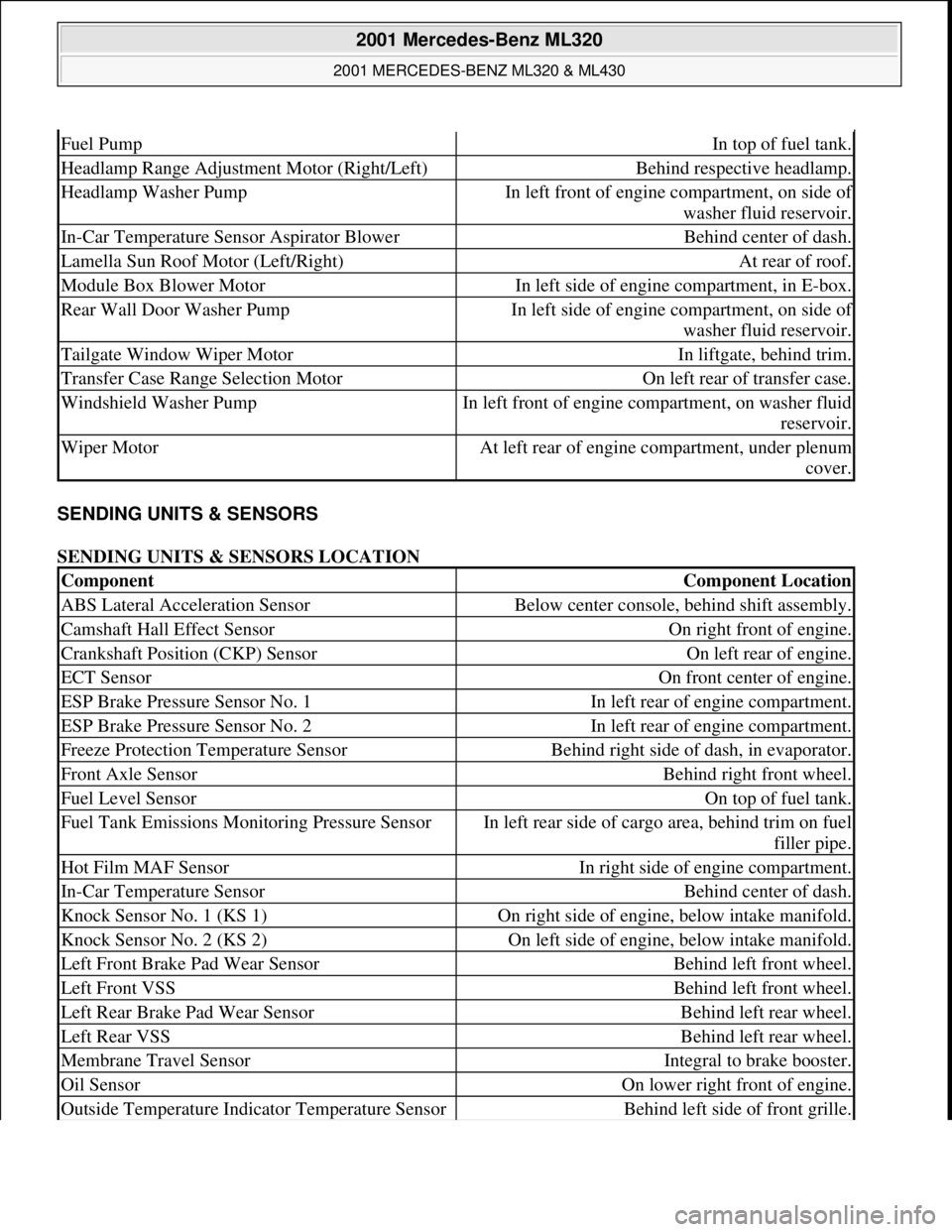
SENDING UNITS & SENSORS
SENDING UNITS & SENSORS LOCATION
Fuel PumpIn top of fuel tank.
Headlamp Range Adjustment Motor (Right/Left)Behind respective headlamp.
Headlamp Washer PumpIn left front of engine compartment, on side of
washer fluid reservoir.
In-Car Temperature Sensor Aspirator BlowerBehind center of dash.
Lamella Sun Roof Motor (Left/Right)At rear of roof.
Module Box Blower MotorIn left side of engine compartment, in E-box.
Rear Wall Door Washer PumpIn left side of engine compartment, on side of
washer fluid reservoir.
Tailgate Window Wiper MotorIn liftgate, behind trim.
Transfer Case Range Selection MotorOn left rear of transfer case.
Windshield Washer PumpIn left front of engine compartment, on washer fluid
reservoir.
Wiper MotorAt left rear of engine compartment, under plenum
cover.
ComponentComponent Location
ABS Lateral Acceleration SensorBelow center console, behind shift assembly.
Camshaft Hall Effect SensorOn right front of engine.
Crankshaft Position (CKP) SensorOn left rear of engine.
ECT SensorOn front center of engine.
ESP Brake Pressure Sensor No. 1In left rear of engine compartment.
ESP Brake Pressure Sensor No. 2In left rear of engine compartment.
Freeze Protection Temperature SensorBehind right side of dash, in evaporator.
Front Axle SensorBehind right front wheel.
Fuel Level SensorOn top of fuel tank.
Fuel Tank Emissions Monitoring Pressure SensorIn left rear side of cargo area, behind trim on fuel
filler pipe.
Hot Film MAF SensorIn right side of engine compartment.
In-Car Temperature SensorBehind center of dash.
Knock Sensor No. 1 (KS 1)On right side of engine, below intake manifold.
Knock Sensor No. 2 (KS 2)On left side of engine, below intake manifold.
Left Front Brake Pad Wear SensorBehind left front wheel.
Left Front VSSBehind left front wheel.
Left Rear Brake Pad Wear SensorBehind left rear wheel.
Left Rear VSSBehind left rear wheel.
Membrane Travel SensorIntegral to brake booster.
Oil SensorOn lower right front of engine.
Outside Temperature Indicator Temperature SensorBehind left side of front grille.
2001 Mercedes-Benz ML320
2001 MERCEDES-BENZ ML320 & ML430
me
Saturday, October 02, 2010 3:21:17 PMPage 4 © 2006 Mitchell Repair Information Company, LLC.
Page 2151 of 4133
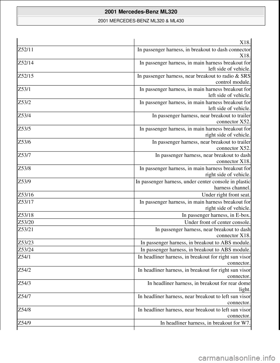
X18.
Z52/11In passenger harness, in breakout to dash connector
X18.
Z52/14In passenger harness, in main harness breakout for
left side of vehicle.
Z52/15In passenger harness, near breakout to radio & SRS
control module.
Z53/1In passenger harness, in main harness breakout for
left side of vehicle.
Z53/2In passenger harness, in main harness breakout for
left side of vehicle.
Z53/4In passenger harness, near breakout to trailer
connector X52.
Z53/5In passenger harness, in main harness breakout for
right side of vehicle.
Z53/6In passenger harness, near breakout to trailer
connector X52.
Z53/7In passenger harness, near breakout to dash
connector X18.
Z53/8In passenger harness, in main harness breakout for
right side of vehicle.
Z53/9In passenger harness, under center console in plastic
harness channel.
Z53/16Under right front seat.
Z53/17In passenger harness, in main harness breakout for
right side of vehicle.
Z53/18In passenger harness, in E-box.
Z53/20Under front of center console.
Z53/21In passenger harness, near breakout to dash
connector X18.
Z53/23In passenger harness, in breakout to ABS module.
Z53/24In passenger harness, in breakout to ABS module.
Z54/1In headliner harness, in breakout for right sun visor
connector.
Z54/2In headliner harness, in breakout for right sun visor
connector.
Z54/3In headliner harness, in breakout for rear dome
light.
Z54/7In headliner harness, near breakout to left sun visor
connector.
Z54/8In headliner harness, near breakout to left sun visor
connector.
Z54/9In headliner harness, in breakout for W7.
2001 Mercedes-Benz ML320
2001 MERCEDES-BENZ ML320 & ML430
me
Saturday, October 02, 2010 3:21:17 PMPage 11 © 2006 Mitchell Repair Information Company, LLC.
Page 2277 of 4133
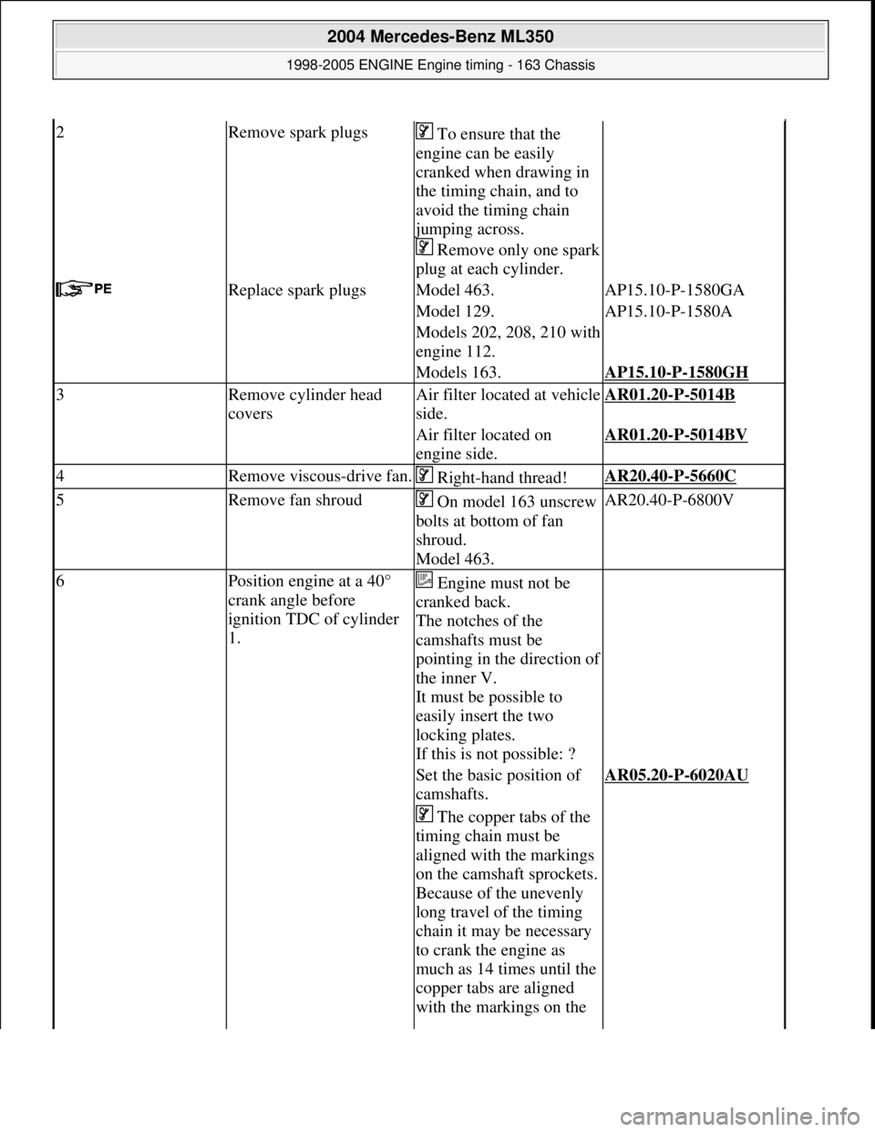
2Remove spark plugs To ensure that the
engine can be easily
cranked when drawing in
the timing chain, and to
avoid the timing chain
jumping across.
Remove only one spark
plug at each cylinder.
Replace spark plugsModel 463.AP15.10-P-1580GA
Model 129.AP15.10-P-1580A
Models 202, 208, 210 with
engine 112.
Models 163.AP15.10-P-1580GH
3Remove cylinder head
coversAir filter locat ed at vehicle
side.AR01.20-P-5014B
Air filter located on
engine side.AR01.20-P-5014BV
4Remove viscous-drive fan. Right-hand thread!AR20.40-P-5660C
5Remove fan shroud On model 163 unscrew
bolts at bottom of fan
shroud.
Model 463.AR20.40-P-6800V
6Position engine at a 40°
crank angle before
ignition TDC of cylinder
1. Engine must not be
cranked back.
The notches of the
camshafts must be
pointing in the direction of
the inner V.
It must be possible to
easily insert the two
locking plates.
If this is not possible: ?
Set the basic position of
camshafts.AR05.20-P-6020AU
The copper tabs of the
timing chain must be
aligned with the markings
on the camshaft sprockets.
Because of the unevenly
long travel of the timing
chain it may be necessary
to crank the engine as
much as 14 times until the
copper tabs are aligned
with the markings on the
2004 Mercedes-Benz ML350
1998-2005 ENGINE Engine timing - 163 Chassis
me
Saturday, October 02, 2010 3:39:37 PMPage 36 © 2006 Mitchell Repair Information Company, LLC.
Page 2523 of 4133
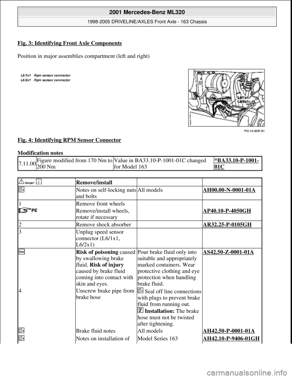
Fig. 3: Identifying Front Axle Components
Position in major assemblies compartment (left and right)
Fig. 4: Identifying RPM Sensor Connector
Modification notes
7.11.00Figure modified from 170 Nm to
200 NmValue in BA33.10-P-1001-01C changed
for Model 163*BA33.10-P-1001-
01C
Remove/install
Notes on self-locking nuts
and boltsAll modelsAH00.00-N-0001-01A
1Remove front wheels
Remove/install wheels,
rotate if necessaryAP40.10-P-4050GH
2Remove shock absorber AR32.25-P-0105GH
3Unplug speed sensor
connector (L6/1x1,
L6/2x1)
Risk of poisoning caused
by swallowing brake
fluid. Risk of injury
caused by brake fluid
coming into contact with
skin and eyes.Pour brake fluid only into
suitable and appropriately
marked containers. Wear
protective clothing and eye
protection when handling
brake fluid.AS42.50-Z-0001-01A
4Unscrew brake pipe from
brake hoseSeal off line connections
with plugs to prevent brake
fluid from running out.
Installation: The brake
hose must not be twisted
after tightening.
Brake fluid notesAll modelsAH42.50-P-0001-01A
Notes on installation of Model Series 163AH42.10-P-9406-01GH
2001 Mercedes-Benz ML320
1998-2005 DRIVELINE/AXLES Front Axle - 163 Chassis
me
Saturday, October 02, 2010 3:38:21 PMPage 4 © 2006 Mitchell Repair Information Company, LLC.
Page 2532 of 4133
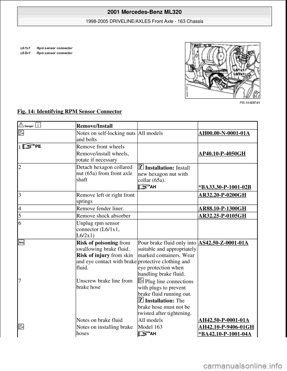
Fig. 14: Identifying RPM Sensor Connector
Remove/Install
Notes on self-locking nuts
and boltsAll modelsAH00.00-N-0001-01A
1 Remove front wheels
Remove/install wheels,
rotate if necessaryAP40.10-P-4050GH
2Detach hexagon collared
nut (65a) from front axle
shaft Installation: Install
new hexagon nut with
collar (65a).
*BA33.30-P-1001-02B
3Remove left or right front
springs AR32.20-P-0200GH
4Remove fender liner. AR88.10-P-1300GH
5Remove shock absorber AR32.25-P-0105GH
6Unplug rpm sensor
connector (L6/1x1,
L6/2x1)
Risk of poisoning from
swallowing brake fluid.
Risk of injury from skin
and eye contact with brake
fluid.Pour brake fluid only into
suitable and appropriately
marked containers. Wear
protective clothing and
eye protection when
handling brake fluid.AS42.50-Z-0001-01A
7Unscrew brake line from
brake hose Plug line connections
with plugs to prevent
brake fluid running out.
Installation: The
brake hose must not be
twisted after tightening.
Notes on brake fluidAll modelsAH42.50-P-0001-01A
Notes on installing brake
hosesModel 163AH42.10-P-9406-01GH
*BA42.10-P-1001-04A
2001 Mercedes-Benz ML320
1998-2005 DRIVELINE/AXLES Front Axle - 163 Chassis
me
Saturday, October 02, 2010 3:38:22 PMPage 13 © 2006 Mitchell Repair Information Company, LLC.
Page 2550 of 4133
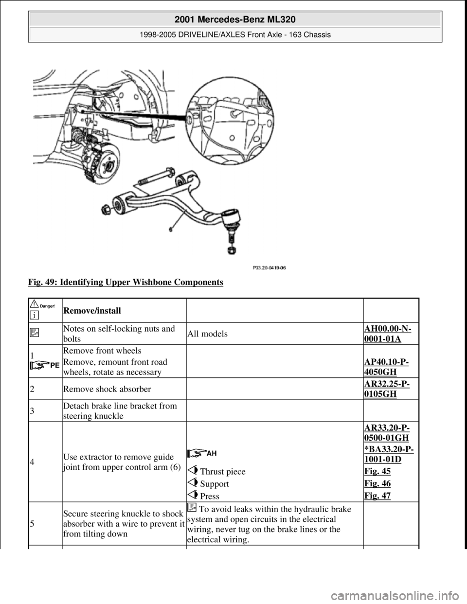
Fig. 49: Identifying Upper Wishbone Components
Remove/install
Notes on self-locking nuts and
boltsAll modelsAH00.00-N-
0001-01A
1
Remove front wheels
Remove, remount front road
wheels, rotate as necessaryAP40.10-P-
4050GH
2Remove shock absorber AR32.25-P-
0105GH
3Detach brake line bracket from
steering knuckle
4Use extractor to remove guide
joint from upper control arm (6)
AR33.20-P-
0500-01GH
*BA33.20-P-
1001-01D
Thrust pieceFig. 45
SupportFig. 46
PressFig. 47
5
Secure steering knuckle to shock
absorber with a wire to prevent it
from tilting down To avoid leaks within the hydraulic brake
system and open circuits in the electrical
wiring, never tug on the brake lines or the
electrical wiring.
2001 Mercedes-Benz ML320
1998-2005 DRIVELINE/AXLES Front Axle - 163 Chassis
me
Saturday, October 02, 2010 3:38:22 PMPage 31 © 2006 Mitchell Repair Information Company, LLC.
Page 2610 of 4133

21
Detach rear brake cables
Unclip at underfloor of vehicle and
unscrew brake cable holder on right and left
at frame.
22.1
Unbolt check strap of rear axle carrier from
underfloor of vehicle
As of VIN A145273, X708319.
23
Remove left rear stone shield
24
Remove lower tensioning straps (80/2) and
loosen the upper tensioning straps
Tensioning straps are color-coded and
cannot be mixed up.
Support fuel tank using assembly jack.
*BA47.10-P-1001-01D
25
Remove longitudinal strut for tensioning
straps (80/18)
*BA47.10-P-1002-01D
26.1
Unscrew linkage for headlamp range
adjustment
at the top
If installed.
27
Unscrew nuts on bottom of the shock
absorbers at the transverse control arm
Installation:
Install new self-locking nuts.
*BA32.25-P-1001-03D
28
Unscrew rear axle carrier from floor of vehicle
and lower as far as possible
Support rear axle carrier.
Installation:
Install new self-locking bolts.
*BA35.10-P-1001-01C
29
Lower fuel tank
Support fuel tank.
30
Remove upper tensioning strap
at the rear
The tensioning strap at the top at the front.
31.1
Unclip lines from side of fuel tank
As of VIN A289565, X754620.
Installation:
The lines must not be
damaged.
32
Disconnect fuel pump electrical plug
connection
33
Disconnect fuel feed line (90/12) and fuel
return line (90/11)
Fuel lines must not be bent.
Pliers
*163589003700
34
Remove fuel tank (80)
Installation:
Ensure that the sealing
rubbers (5) seat correctly in the body floor to
prevent water entry.
Do not damage fuel lines at filler neck.
Guide filler neck with its chamfered side
(arrow) through between frame and body.
Filler neck and fuel tank cannot be separated
from each other.
35
Install in the reverse order
36.1
Dispose of fuel tank
Ony when replacing the fuel tank.
o
Disposal of fuel tanks
OS47.10-P-0001-01A
Rear axle carrier
Number
Designation
Model
Series 163
BA35.10-P-1001-01C
Self-locking bolt, rear axle carrier at front and rear
to frame floor
Nm
200
Propeller shaft
Number
Designation
Model
Series 163
BA41.10-P-1002-01C
Self-locking bolt, rear propsharft
at rear axle center section
Nm
50
Copyright DaimlerChrysler AG 28.05.2006 CD-Ausgabe G/10/04 . This WIS print-out will not be recorde
d by Modification services.
Page 3