1997 MERCEDES-BENZ ML430 ABS
[x] Cancel search: ABSPage 3928 of 4133
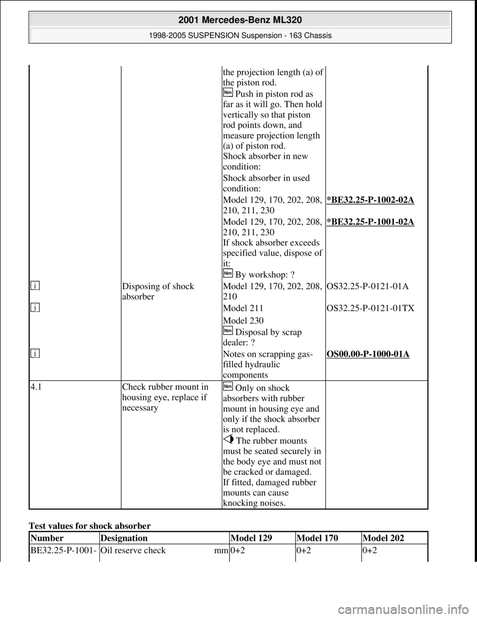
Test values for shock absorber
the projection length (a) of
the piston rod.
Push in piston rod as
far as it will go. Then hold
vertically so that piston
rod points down, and
measure projection length
(a) of piston rod.
Shock absorber in new
condition:
Shock absorber in used
condition:
Model 129, 170, 202, 208,
210, 211, 230*BE32.25-P-1002-02A
Model 129, 170, 202, 208,
210, 211, 230
If shock absorber exceeds
specified value, dispose of
it:
By workshop: ?*BE32.25-P-1001-02A
Disposing of shock
absorberModel 129, 170, 202, 208,
210OS32.25-P-0121-01A
Model 211OS32.25-P-0121-01TX
Model 230
Disposal by scrap
dealer: ?
Notes on scrapping gas-
filled hydraulic
componentsOS00.00-P-1000-01A
4.1Check rubber mount in
housing eye, replace if
necessary Only on shock
absorbers with rubber
mount in housing eye and
only if the shock absorber
is not replaced.
The rubber mounts
must be seated securely in
the body eye and must not
be cracked or damaged.
If fitted, damaged rubber
mounts can cause
knocking noises.
NumberDesignationModel 129Model 170Model 202
BE32.25-P-1001- Oil reserve check mm0+20+20+2
2001 Mercedes-Benz ML320
1998-2005 SUSPENSION Suspension - 163 Chassis
me
Saturday, October 02, 2010 3:37:36 PMPage 20 © 2006 Mitchell Repair Information Company, LLC.
Page 3929 of 4133
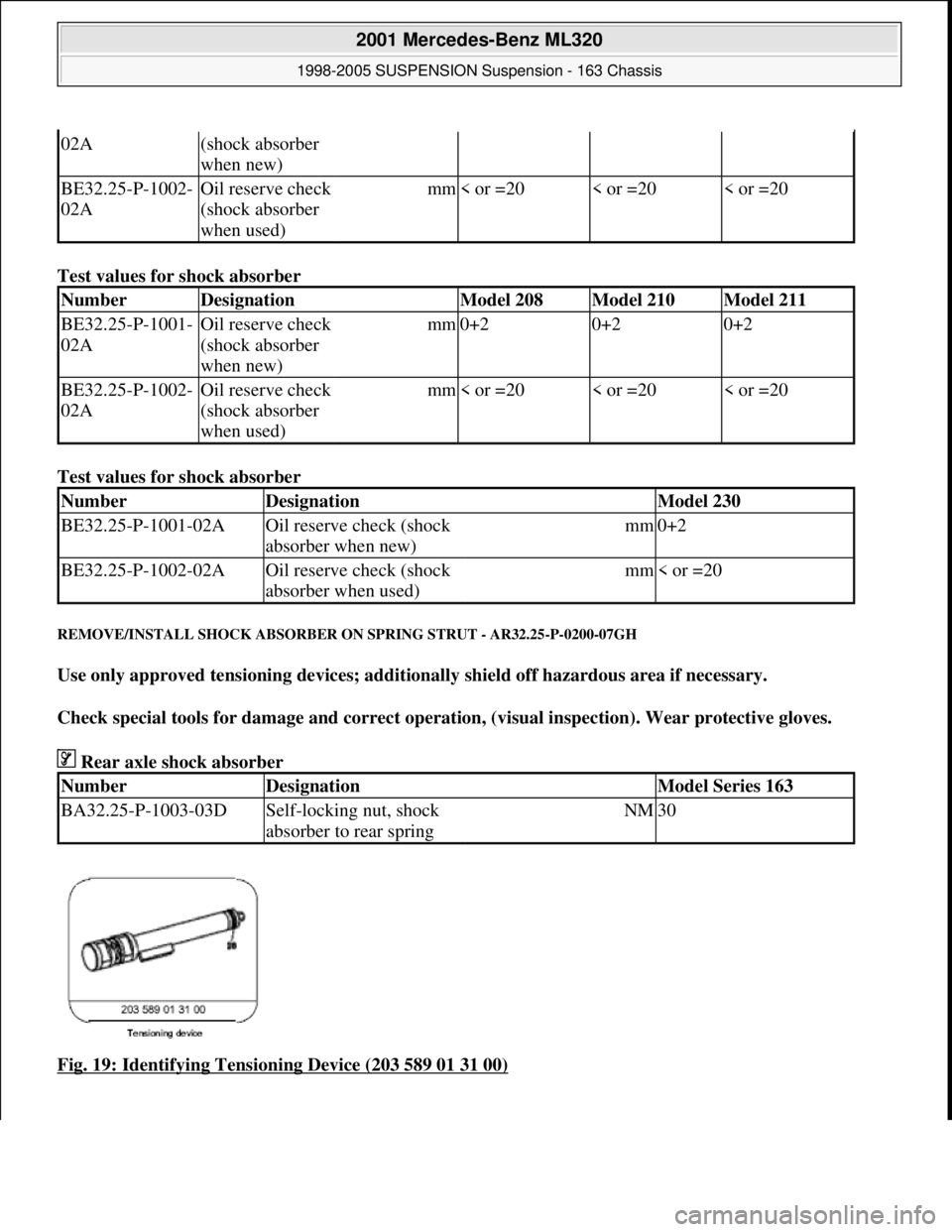
Test values for shock absorber
Test values for shock absorber
REMOVE/INSTALL SHOCK ABSORBER ON SPRING STRUT - AR32.25-P-0200-07GH
Use only approved tensioning devices; additionally shield off hazardous area if necessary.
Check special tools for damage and correct operation, (visual inspection). Wear protective gloves.
Rear axle shock absorber
Fig. 19: Identifying Tensioning Device (203 589 01 31 00)
02A(shock absorber
when new)
BE32.25-P-1002-
02AOil reserve check
(shock absorber
when used)mm< or =20< or =20< or =20
NumberDesignationModel 208Model 210Model 211
BE32.25-P-1001-
02AOil reserve check
(shock absorber
when new)mm0+20+20+2
BE32.25-P-1002-
02AOil reserve check
(shock absorber
when used)mm< or =20< or =20< or =20
NumberDesignationModel 230
BE32.25-P-1001-02AOil reserve check (shock
absorber when new)mm0+2
BE32.25-P-1002-02AOil reserve check (shock
absorber when used)mm< or =20
NumberDesignationModel Series 163
BA32.25-P-1003-03DSelf-locking nut, shock
absorber to rear springNM30
2001 Mercedes-Benz ML320
1998-2005 SUSPENSION Suspension - 163 Chassis
me
Saturday, October 02, 2010 3:37:36 PMPage 21 © 2006 Mitchell Repair Information Company, LLC.
Page 3932 of 4133
When replacing the rear spring, support bearing or rear spring guide, the markings from the old
components must be taken over.
8. Compress rear spring.
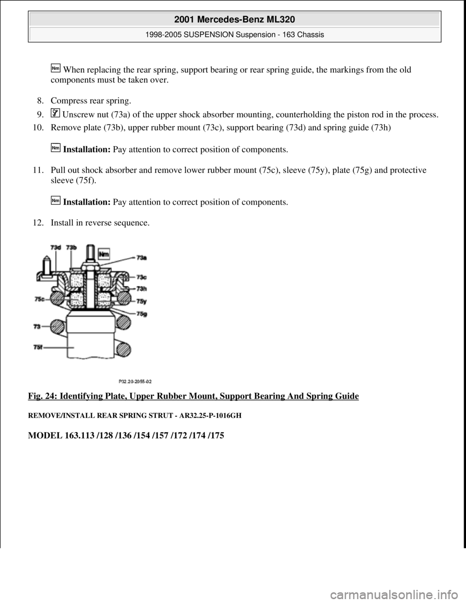
9. Unscrew nut (73a) of the upper shock absorber mounting, counterholding the piston rod in the process.
10. Remove plate (73b), upper rubber mount (73c), support bearing (73d) and spring guide (73h)
Installation: Pay attention to correct position of components.
11. Pull out shock absorber and remove lower rubber mount (75c), sleeve (75y), plate (75g) and protective
sleeve (75f).
Installation: Pay attention to correct position of components.
12. Install in reverse sequence.
Fig. 24: Identifying Plate, Upper Rubber Mount, Support Bearing And Spring Guide
REMOVE/INSTALL REAR SPRING STRUT - AR32.25-P-1016GH
MODEL 163.113 /128 /136 /154 /157 /172 /174 /175
2001 Mercedes-Benz ML320
1998-2005 SUSPENSION Suspension - 163 Chassis
me
Saturday, October 02, 2010 3:37:36 PMPage 24 © 2006 Mitchell Repair Information Company, LLC.
Page 3934 of 4133
Rear axle torsion strut
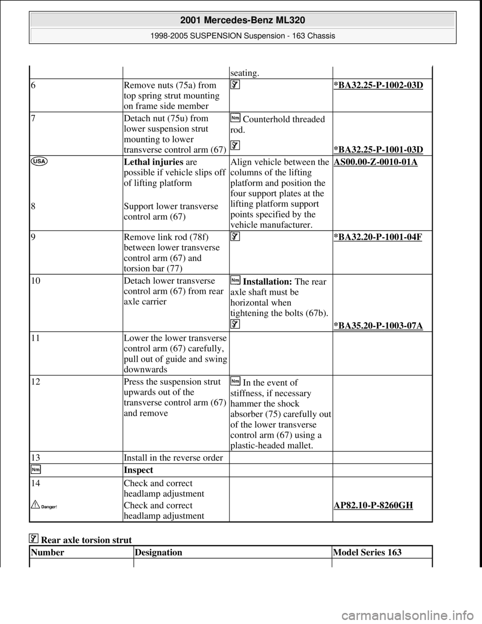
seating.
6Remove nuts (75a) from
top spring strut mounting
on frame side member *BA32.25-P-1002-03D
7Detach nut (75u) from
lower suspension strut
mounting to lower
transverse control arm (67) Counterhold threaded
rod.
*BA32.25-P-1001-03D
Lethal injuries are
possible if vehicle slips off
of lifting platformAlign vehicle between the
columns of the lifting
platform and position the
four support plates at the
lifting platform support
points specified by the
vehicle manufacturer.AS00.00-Z-0010-01A
8Support lower transverse
control arm (67)
9Remove link rod (78f)
between lower transverse
control arm (67) and
torsion bar (77) *BA32.20-P-1001-04F
10Detach lower transverse
control arm (67) from rear
axle carrier Installation: The rear
axle shaft must be
horizontal when
tightening the bolts (67b).
*BA35.20-P-1003-07A
11Lower the lower transverse
control arm (67) carefully,
pull out of guide and swing
downwards
12Press the suspension strut
upwards out of the
transverse control arm (67)
and remove In the event of
stiffness, if necessary
hammer the shock
absorber (75) carefully out
of the lower transverse
control arm (67) using a
plastic-headed mallet.
13Install in the reverse order
Inspect
14Check and correct
headlamp adjustment
Check and correct
headlamp adjustment AP82.10-P-8260GH
NumberDesignationModel Series 163
2001 Mercedes-Benz ML320
1998-2005 SUSPENSION Suspension - 163 Chassis
me
Saturday, October 02, 2010 3:37:36 PMPage 26 © 2006 Mitchell Repair Information Company, LLC.
Page 3935 of 4133
Rear axle shock absorber
Wheel location
REMOVAL & INSTALLATION
INSTALLING PINCH NUT ON REAR STABILIZER BAR CONNECTING ROD BOLT - SM32.35-P-0001A
MODEL 163.154 #A as of 000001 up to 014254
Vehicles within the Effective Serial Number Range, must have the following work performed during next
scheduled maintenance or service. Install pinch nut to ensure proper tightening torque of rear stabilizer bar
mounting.
Damage code for warranty/goodwill claim: 32 920 07
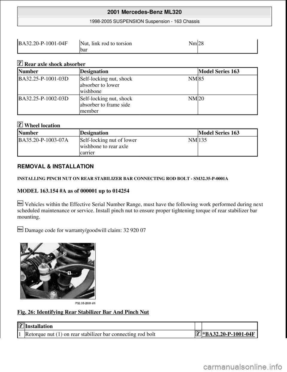
Fig. 26: Identifying Rear Stabilizer Bar And Pinch Nut
BA32.20-P-1001-04FNut, link rod to torsion
barNm28
NumberDesignationModel Series 163
BA32.25-P-1001-03DSelf-locking nut, shock
absorber to lower
wishboneNM85
BA32.25-P-1002-03DSelf-locking nut, shock
absorber to frame side
memberNM20
NumberDesignationModel Series 163
BA35.20-P-1003-07ASelf-locking nut of lower
wishbone to rear axle
carrierNM135
Installation
1Retorque nut (1) on rear stabilizer bar connecting rod bolt*BA32.20-P-1001-04F
2001 Mercedes-Benz ML320
1998-2005 SUSPENSION Suspension - 163 Chassis
me
Saturday, October 02, 2010 3:37:36 PMPage 27 © 2006 Mitchell Repair Information Company, LLC.
Page 3961 of 4133

AD54.30-P-5000-02A
Display instruments controlled via CAN
troubleshooting chart IC
The following display instruments or indicator lamps/ malfunction
indicator lamps receive their information from the traction system
control module (N47) via CAN data buses (an appropriate message
appears in the display on vehicles with multi-function display):
D
Total mileage recorder, trip odometer
D
Electronic speedometer
D
Low brake fluid level/parking brake indicator lamp (except model 163
parking brake indicator lamp only via CAN)
D
Brake pad wear indicator lamp
D
ABS MIL
D
ETS, ASR, ESP indicator lamp
D
ETS, ASR, ESP malfunction indicator lamp
Model 163 only:
The
"Low-Range"
indicator lamp receives its information from the
transfer case control module (N78) via CAN data buses.
The
"Fog lamps"
indicator lamp (only model 163 except
I
) receives
its information from the All-activity module (AAM, N10) via CAN data
buses.
Model 168 only:
The
" Gear indicator "
indicator lamp receives its information from the
gear recognition module (A61) or from automatic clutch control module
(N15/4) via CAN data buses.
The following display instruments or indicator lamps/
malfunction indicator lamps receive their information from the
injection system control module (N3) via CAN data buses (an
appropriate message appears in the display on vehicles with
multi-function display):
D
Tachometer
D
Low engine oil level lamp
D
Engine coolant temperature
D
Preglow indicator lamp (diesel only)
D
Vehicle speed warning
D
Vehicle speed limit warning
D
Severe leak warning (
I
only), the fuel reserve indicator lamp
(A1e4) flashes
D
Active Service System (ASSYST):
D
Oil condition
D
Oil level
D
Oil temperature
D
Mass volumetric efficiency (load moment)
D
Engine speed, engine coolant temperature
Copyright DaimlerChrysler AG 05.06.2006 CD-Ausgabe G/10/04 . This WIS print-out will not be recorde
d by Modification services.
Page 1
Page 3969 of 4133

6
Notes:
• Your phone plays a confirmation beep when docked. Wait for this beep before undocking.
• While in Vehicular Mode, the phone operates on the vehicle’s integrated cellular antenna.
CC C C
aa a a
uu u u
tt t t
iii i
oo o o
nn n n
::: :
Mercedes-Benz recommends keeping the phone docked in the cradle while operating the vehicle. If you
must use the handset for privacy operation, stop the vehicle prior to removing the phone from the cradle.
Installing the Special Battery Insert
The V60 cradle is supplied with a special insert to make it easier to align the phone with the cradle’s embedded connector
when you use certain batteries.
YY Y Y
oo o o
uu u u
ss s s
hh h h
oo o o
uu u u
lll l
dd d d
oo o o
nn n n
lll l
yy y y
iii i
nn n n
ss s s
tt t t
aa a a
lll l
lll l
tt t t
hh h h
iii i
ss s s
iii i
nn n n
ss s s
ee e e
rr r r
tt t t
iii i
ff f f
yy y y
oo o o
uu u u
aa a a
rr r r
ee e e
uu u u
ss s s
iii i
nn n n
gg g g
tt t t
hh h h
ee e e
ss s s
lll l
iii i
mm m m
oo o o
rr r r
hh h h
iii i
gg g g
hh h h
pp p p
ee e e
rr r r
ff f f
oo o o
rr r r
mm m m
aa a a
nn n n
cc c c
ee e e
bb b b
aa a a
tt t t
tt t t
ee e e
rr r r
yy y y
... .
The slim battery is supplied as a standard component in the CDMA V60 kit, while the high performance battery is standard
in the TDMA V60 kit. You should remove the insert when using the optional extra capacity battery.
To install the insert:
44 4 4
Pivot the cradle down to securely latch it.
NN N N
oo o o
tt t t
ee e e
::: :
The cradle should never be placed into the holder with the phone’s flip open.
CC C C
lll l
oo o o
ss s s
ee e e
tt t t
hh h h
ee e e
ff f f
lll l
iii i
pp p p
bb b b
ee e e
ff f f
oo o o
rr r r
ee e e
ss s s
ee e e
cc c c
uu u u
rr r r
iii i
nn n n
gg g g
tt t t
hh h h
ee e e
cc c c
rr r r
aa a a
dd d d
lll l
ee e e
iii i
nn n n
tt t t
hh h h
ee e e
hh h h
oo o o
lll l
dd d d
ee e e
rr r r
in order to prevent damage to the phone when the console cover is closed.
Step
11 1 1
Align the four tabs on the side of the insert with the corresponding slots in the cradle.
22 2 2
Gently push the insert into the slots until it snaps into place.
If you are using the slim battery, the side marked “FOR USE WITH SLIM BATTERY” should face up.
If you are using the high performance battery, the side marked “FOR USE WITH HIGH PERFORMANCE BATTERY” should face up.
33 3 3
If you plan to use the extra capacity battery with your phone, remove the insert by gently prying it out with a small
flat screwdriver, exercising care not to mar the side walls of the cradle.
Step