1997 MERCEDES-BENZ ML430 ABS
[x] Cancel search: ABSPage 1542 of 4133
SAFETY SHUTOFF (WSA) - FUNCTION - GF82.30-P-3005GH
MODEL 163 Applicable as of 1.9.00
Safety shutoff
The intermittent wipe function is interrupted when the vehicle comes to a complete stop and at least one of
the front doors is open. Any wipe cycle in progress is completed before wipers come to a halt.
Wiping resumes when both front doors are closed and/or the vehicle is put into motion.
The safety shutoff therefore only operates when the vehicle is at a complete stop. This ensures that the
intermittent wiping feature remains available during driving even if a door jamb switch is defective.
ANTI-LOCK PROTECTION FOR WIPER MOTOR, FUNCTION - GF82.30-P-4008GH
MODEL 163
The all-activity module(AAM) (N10) recognizes that the wiper motor (M6/1) is locked up because of the
absence of signals from the cam switch.
If signals are not recognized for longer than 1 s the front wiper motor relay (F1k17) is no longer actuated.
The anti-lock protection is only effective in the function interval wiping . In other wiper stages the AAM does
not have influence on the wiper motor.
RAIN SENSOR - FUNCTION - GF82.30-P-4103-02GH
location/purpose/design/function4100GH
as of 1.12.99GF54.21-P-
4100GK
Extended activity module,
location/purposeas of 1.12.99GF54.21-P-
4106GH
Windshield Intermittent
Wipe - Function GF82.30-P-3003GH
Wiper motor,
location/purpose/design/function GF82.30-P-
4104GH
All-activity module (AAM),
location/purpose/ design/functionup to 30.11.99GF54.21-P-
4100GH
as of 1.12.99GF54.21-P-
4100GK
2001 Mercedes-Benz ML320
1998-2005 ACCESSORIES & BODY, CAB Electrical System - Body - 163 Chassis
me
Saturday, October 02, 2010 3:30:04 PMPage 47 © 2006 Mitchell Repair Information Company, LLC.
Page 1574 of 4133
automatically, after voltage to the radio (A2) was interrupted
manually, by activating the "SPRA" menu in the navigation mode
Loading the language requires approx. 20 s.
If the system is switched off while loading the language, the language data is lost and must be reloaded again.
Avoid strong vibrations to the vehicle (e.g. extremely bumpy roads) while the language is being loaded.
The navigation processor is integrated in the radio (A2).
BASIC LOCATION FINDING, FUNCTION - GF82.61-P-3006D
MODELS 163, 168, 170, 203.0 /2 /7, 208, 209.3 /4, 210 with CODE (353) Audio 30 APS
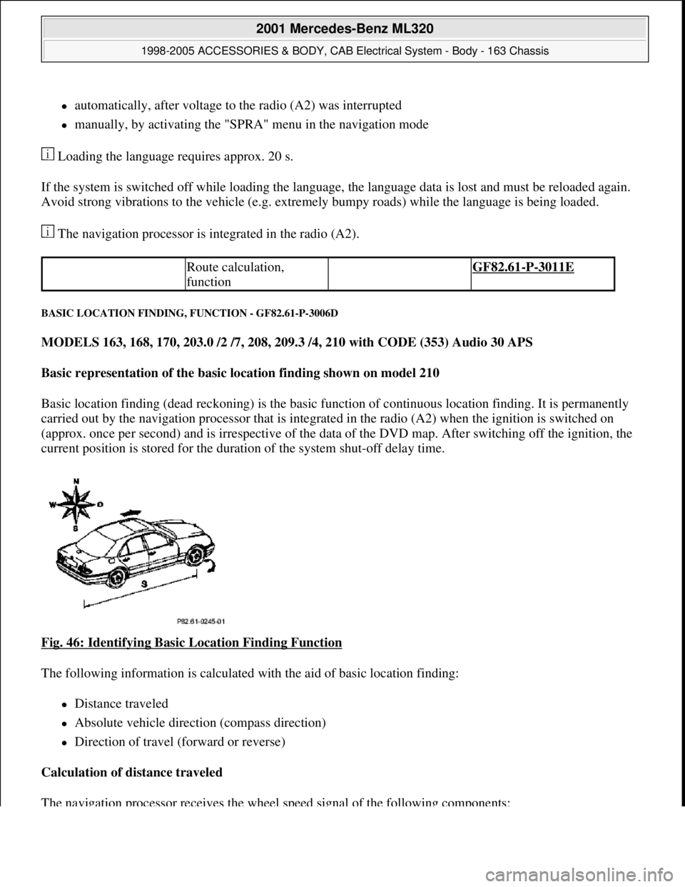
Basic representation of the basic location finding shown on model 210
Basic location finding (dead reckoning) is the basic function of continuous location finding. It is permanently
carried out by the navigation processor that is integrated in the radio (A2) when the ignition is switched on
(approx. once per second) and is irrespective of the data of the DVD map. After switching off the ignition, the
current position is stored for the duration of the system shut-off delay time.
Fig. 46: Identifying Basic Location Finding Function
The following information is calculated with the aid of basic location finding:
Distance traveled
Absolute vehicle direction (compass direction)
Direction of travel (forward or reverse)
Calculation of distance traveled
The navi
gation processor receives the wheel speed signal of the following components:
Route calculation,
function GF82.61-P-3011E
2001 Mercedes-Benz ML320
1998-2005 ACCESSORIES & BODY, CAB Electrical System - Body - 163 Chassis
me
Saturday, October 02, 2010 3:30:05 PMPage 79 © 2006 Mitchell Repair Information Company, LLC.
Page 1658 of 4133
Risk of explosion/risk of fire
Highly flammable materials in the vicinity of damaged, energized xenon bulbs may result in explosion or cause
fires.
Risk of injury
UV light may escape when operating xenon bulbs not properly installed in the xenon headlamps. This UV light
may cause damage to the eyes (conjunctival infection) and to skin burns (sunburns) if skin is unprotected.
In both intact or faulty xenon headlamps, hot or glowing components may cause serious burn injuries if they
come into contact with unprotected skin or eyes.
Glass splinters produced by the destruction of xenon bulbs may cause cut injuries in unprotected skin and
unprotected eyes.
Risk of poisoning
When xenon bulbs are destroyed, serious health problems may be caused if the mercury vapors produced are
inhaled or if mercury compounds or toxic salts are ingested or absorbed through the skin. Possible
consequences include nausea, vomiting and gastrointestinal disruptions as well as degradation of the kidneys
and the central nervous system. Skin and eye damage may also result.
Safety precautions/instructions
Persons with electronic implants (e.g. pacemakers) must never work on xenon headlamps.
Wear safety shoes (with rubber soles).
Prior to working on xenon headlamps (e.g. replacing parts, hooking up test equipment, etc.), the complete
lighting system must be switched off and the xenon headlamps must be disconnected from the on-board
electrical system.
If the xenon headlamps are switched on, never touch components under high voltage.
If the xenon headlamps are switched on, maintain a clearance of at least 30 mm to components under high
voltage.
Avoid all contact with hot components.
Wait at least 3 min after switching off xenon bulbs before touching them.
Do not damage or destroy xenon bulbs.
Safety precautions/instructions
Never operate xenon bulbs unless they are properly installed in xenon headlamps with UV-absorbing
headlamp lenses.
Keep all highly flammable materials away from working area.
Wear suitable protective gloves and safety glasses.
Ensure that the workplace is sufficiently ventilated.
2001 Mercedes-Benz ML320
1998-2005 ACCESSORIES & BODY, CAB Electrical System - Body - 163 Chassis
me
Saturday, October 02, 2010 3:30:06 PMPage 163 © 2006 Mitchell Repair Information Company, LLC.
Page 1710 of 4133
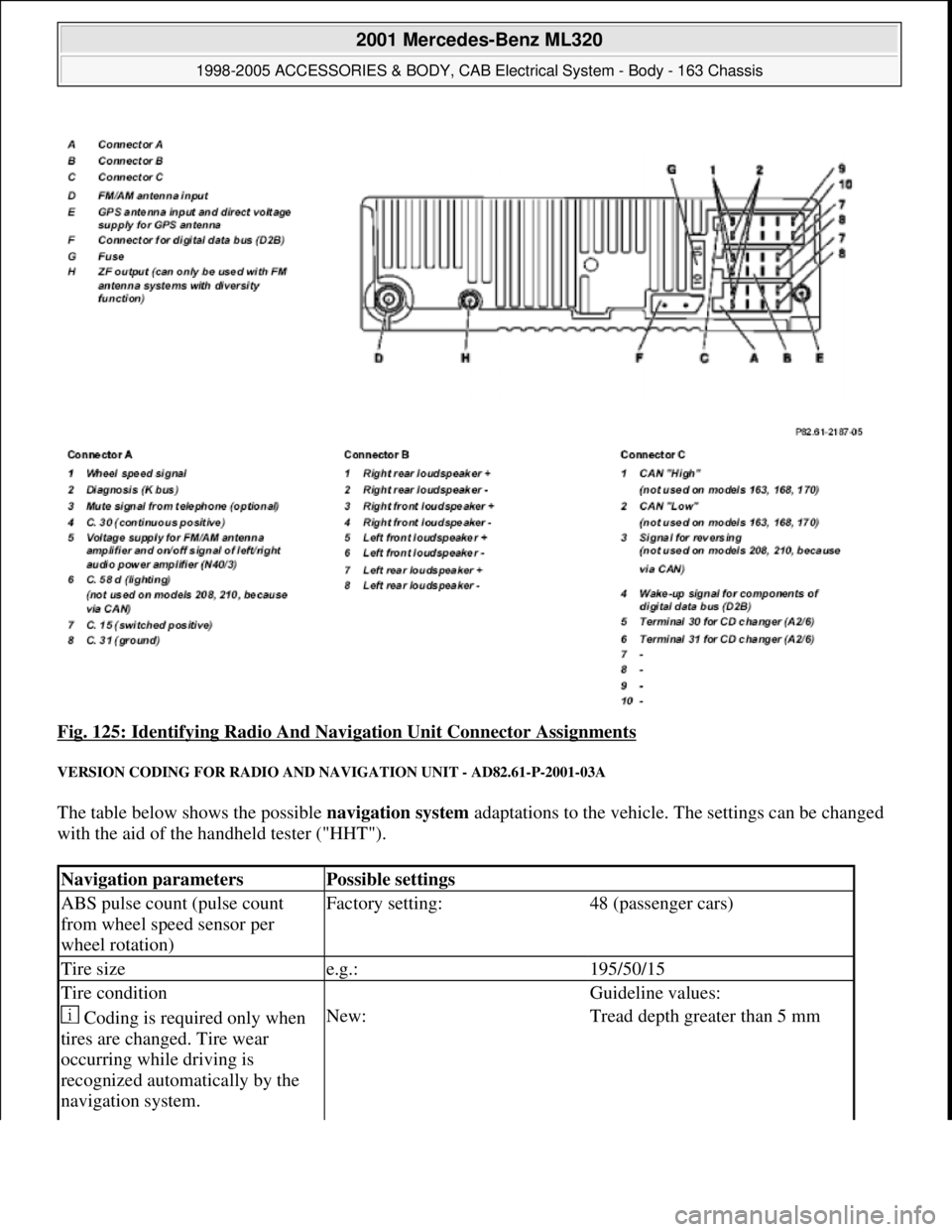
Fig. 125: Identifying Radio And Navigation Unit Connector Assignments
VERSION CODING FOR RADIO AND NAVIGATION UNIT - AD82.61-P-2001-03A
The table below shows the possible navigation system adaptations to the vehicle. The settings can be changed
with the aid of the handheld tester ("HHT").
Navigation parametersPossible settings
ABS pulse count (pulse count
from wheel speed sensor per
wheel rotation)Factory setting:48 (passenger cars)
Tire sizee.g.:195/50/15
Tire condition Guideline values:
Coding is required only when
tires are changed. Tire wear
occurring while driving is
recognized automatically by the
navigation system.New:Tread depth greater than 5 mm
2001 Mercedes-Benz ML320
1998-2005 ACCESSORIES & BODY, CAB Electrical System - Body - 163 Chassis
me
Saturday, October 02, 2010 3:30:08 PMPage 215 © 2006 Mitchell Repair Information Company, LLC.
Page 1728 of 4133
MODEL 163 with CODE (257a) Radio ML 5 except CODE (491) U.S. version
MODEL 168, 208 with MB radio
AM AND FM WAVE BANDS, DIAGNOSIS, FUNCTION CHECK, AS - AD82.62-P-3000-01A
Function check
Set radio as follows: Set station with poor reception (music) and fader, bass, treble and balance in
position 0 (shown in display).
Check AM and FM wave bands by driving in a circle in a yard (open-air grounds) to establish the
reception quality.
Possibly repeat the test with an identical vehicle for comparison.
It is absolutely essential to perform the comparison measurement at the same location and with the same
station setting .
Repeat the test after replacing a component.
ANTENNA SYSTEM (AS) DIAGNOSIS, FUNCTION CHECK - AD82.62-P-3000A
MODELS 163, 168, 202.078 /080 /083 /182 /188, 208 (except, 208.4), 202.01 /02/12 as of 1.1.97, 210.0 /2
Loudspeaker system
(LS), location of
componentsModel 208GF82.62-P-0002-01B
Model 168 ModelGF82.62-P-0002-01C
163GF82.62-P-0002-01D
Electric wiring diagramsModel 208PE82.00-P-1100D
Model 168PE82.00-P-1100GC
Model 163PE82.00-P-1100E
Connection and use of
test equipment AD00.00-P-1000AZ
Diagnostic tools,
loudspeaker system (LS) AD82.62-P-2001-01A
Coupling assignment on
radio for loudspeaker
system (LS) AD82.62-P-2001-02A
Antenna system (AS)
diagnosis, previous
knowledge AD82.62-P-2000A
Operational check
Test of Operation /
Requirement Specified value possible cause/ Remedy
2001 Mercedes-Benz ML320
1998-2005 ACCESSORIES & BODY, CAB Electrical System - Body - 163 Chassis
me
Saturday, October 02, 2010 3:30:08 PMPage 233 © 2006 Mitchell Repair Information Company, LLC.
Page 1812 of 4133
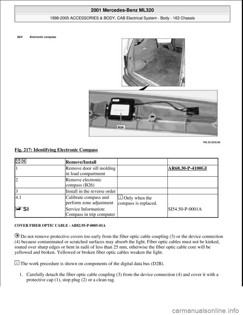
Fig. 217: Identifying Electronic Compass
COVER FIBER OPTIC CABLE - AR82.95-P-0005-01A
Do not remove protective covers too early from the fiber optic cable coupling (3) or the device connection
(4) because contaminated or scratched surfaces may absorb the light. Fiber optic cables must not be kinked,
routed over sharp edges or bent in radii of less than 25 mm, otherwise the fiber optic cable core will be
yellowed and broken. Yellowed or broken fiber optic cables weaken the light.
The work procedure is shown on components of the digital data bus (D2B).
1. Carefully detach the fiber optic cable coupling (3) from the device connection (4) and cover it with a
protective cap (1), stop plug (2) or a clean rag.
Remove/Install
1Remove door sill molding
in load compartment AR68.30-P-4100GI
2Remove electronic
compass (B26)
3Install in the reverse order
4.1Calibrate compass and
perform zone adjustment Only when the
compass is replaced.
Service Information:
Compass in trip computer SI54.50-P-0001A
2001 Mercedes-Benz ML320
1998-2005 ACCESSORIES & BODY, CAB Electrical System - Body - 163 Chassis
me
Saturday, October 02, 2010 3:30:10 PMPage 317 © 2006 Mitchell Repair Information Company, LLC.
Page 1848 of 4133
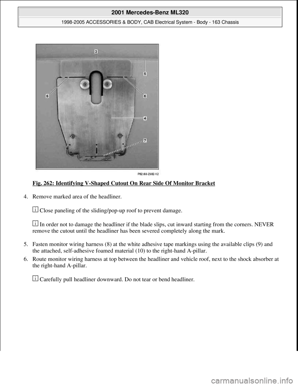
Fig. 262: Identifying V-Shaped Cutout On Rear Side Of Monitor Bracket
4. Remove marked area of the headliner.
Close paneling of the sliding/pop-up roof to prevent damage.
In order not to damage the headliner if the blade slips, cut inward starting from the corners. NEVER
remove the cutout until the headliner has been severed completely along the mark.
5. Fasten monitor wiring harness (8) at the white adhesive tape markings using the available clips (9) and
the attached, self-adhesive foamed material (10) to the right-hand A-pillar.
6. Route monitor wiring harness at top between the headliner and vehicle roof, next to the shock absorber at
the right-hand A-pillar.
Carefull
y pull headliner downward. Do not tear or bend headliner.
2001 Mercedes-Benz ML320
1998-2005 ACCESSORIES & BODY, CAB Electrical System - Body - 163 Chassis
me
Saturday, October 02, 2010 3:30:11 PMPage 353 © 2006 Mitchell Repair Information Company, LLC.
Page 1854 of 4133
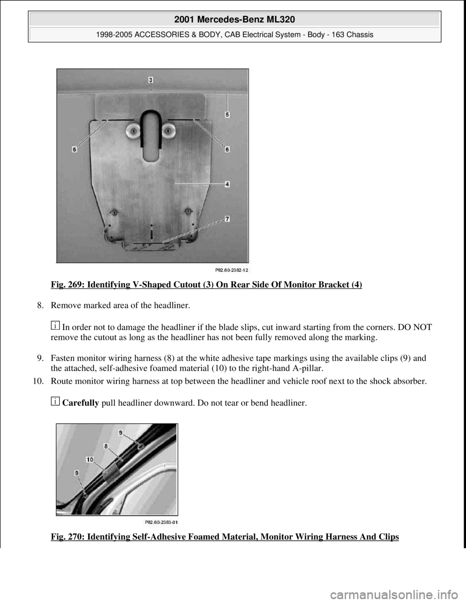
Fig. 269: Identifying V-Shaped Cutout (3) On Rear Side Of Monitor Bracket (4)
8. Remove marked area of the headliner.
In order not to damage the headliner if the blade slips, cut inward starting from the corners. DO NOT
remove the cutout as long as the headliner has not been fully removed along the marking.
9. Fasten monitor wiring harness (8) at the white adhesive tape markings using the available clips (9) and
the attached, self-adhesive foamed material (10) to the right-hand A-pillar.
10. Route monitor wiring harness at top between the headliner and vehicle roof next to the shock absorber.
Carefully pull headliner downward. Do not tear or bend headliner.
Fig. 270: Identifying Self
-Adhesive Foamed Material, Monitor Wiring Harness And Clips
2001 Mercedes-Benz ML320
1998-2005 ACCESSORIES & BODY, CAB Electrical System - Body - 163 Chassis
me
Saturday, October 02, 2010 3:30:11 PMPage 359 © 2006 Mitchell Repair Information Company, LLC.