Page 1860 of 4133
Fig. 276: Identifying V-Shaped Cutout (3) On Rear Side Of Monitor Bracket
4. Remove marked area of the headliner.
Close paneling of the sliding/pop-up roof to prevent damage.
In order not to damage the headliner if the blade slips, cut inward starting from the corners. NEVER
remove the cutout until the headliner has been severed completely along the mark.
5. Fasten monitor wiring harness (8) at the white adhesive tape markings using the available clips (9) and
the attached, self-adhesive foamed material (10) to the left-hand A-pillar.
6. Route monitor wiring harness at top between the headliner and vehicle roof, next to the shock absorber at
the left-hand A-pillar.
Carefull
y pull headliner downward. Do not tear or bend headliner.
2001 Mercedes-Benz ML320
1998-2005 ACCESSORIES & BODY, CAB Electrical System - Body - 163 Chassis
me
Saturday, October 02, 2010 3:30:11 PMPage 365 © 2006 Mitchell Repair Information Company, LLC.
Page 1866 of 4133
Fig. 283: Identifying V-Shaped Cutout (3) On Rear Side Of Monitor Bracket
8. Remove marked area of the headliner.
In order not to damage the headliner if the blade slips, cut inward starting from the corners. NEVER
remove the cutout until the headliner has been removed completely along the mark.
9. Fasten monitor wiring harness (8) at the white adhesive tape markings using the available clips (9) and
the attached, self-adhesive foamed material (10) to the left-hand A-pillar.
10. Route monitor wiring harness at top between the headliner and vehicle roof, next to the shock absorber at
the left-hand A-pillar.
Carefully pull headliner downward. Do not tear or bend headliner.
2001 Mercedes-Benz ML320
1998-2005 ACCESSORIES & BODY, CAB Electrical System - Body - 163 Chassis
me
Saturday, October 02, 2010 3:30:12 PMPage 371 © 2006 Mitchell Repair Information Company, LLC.
Page 1992 of 4133
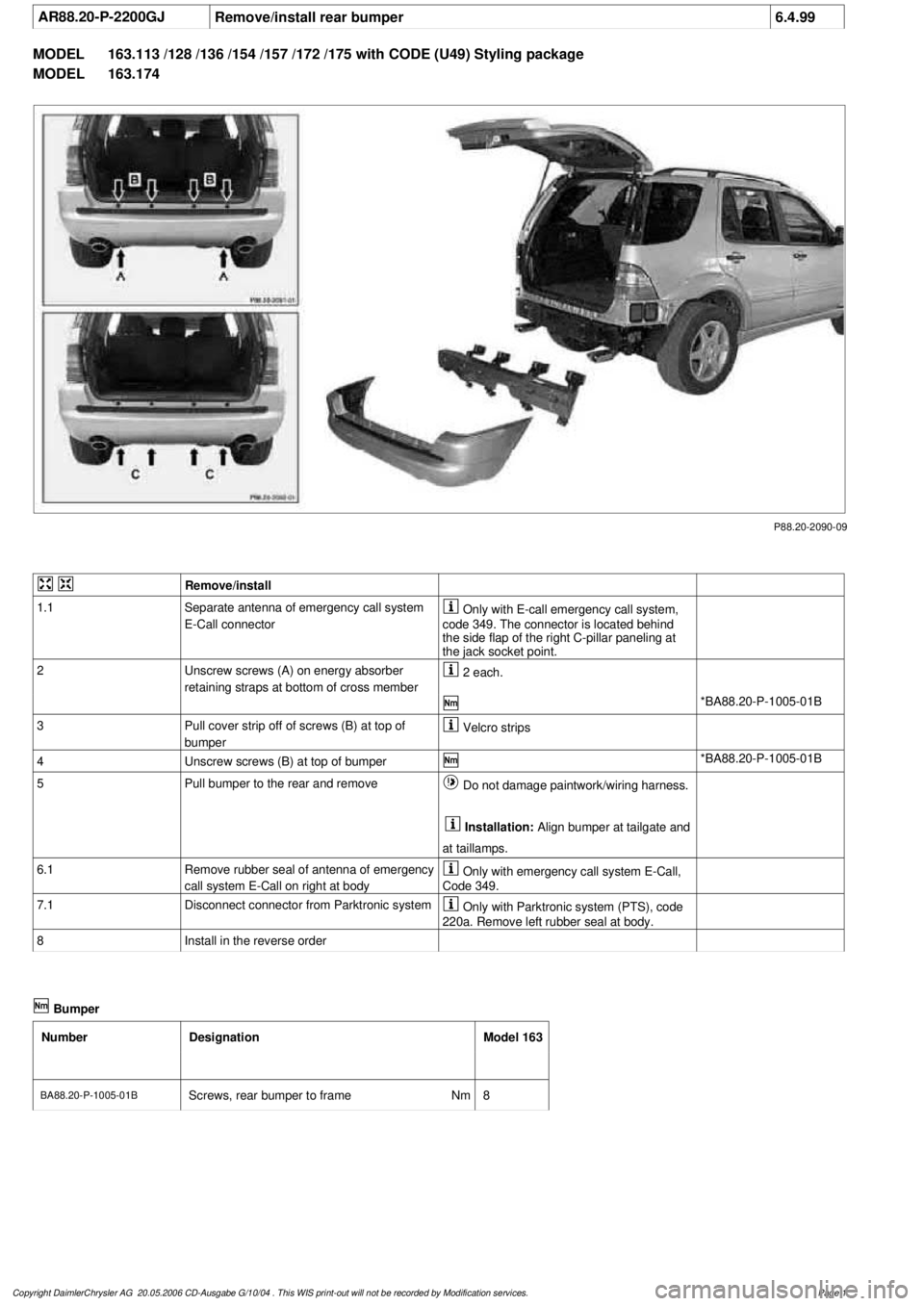
AR88.20-P-2200GJ
Remove/install rear bumper
6.4.99
MODEL
163.113 /128 /136 /154 /157 /172 /175 with CODE (U49) Styling package
MODEL
163.174
P88.20-2090-09
Remove/install
1.1
Separate antenna of emergency call system
E-Call connector
Only with E-call emergency call system,
code 349. The connector is located behind
the side flap of the right C-pillar paneling at
the jack socket point.
2
Unscrew screws (A) on energy absorber
retaining straps at bottom of cross member
2 each.
*BA88.20-P-1005-01B
3
Pull cover strip off of screws (B) at top of
bumper
Velcro strips
4
Unscrew screws (B) at top of bumper
*BA88.20-P-1005-01B
5
Pull bumper to the rear and remove
Do not damage paintwork/wiring harness.
Installation:
Align bumper at tailgate and
at taillamps.
6.1
Remove rubber seal of antenna of emergency
call system E-Call on right at body
Only with emergency call system E-Call,
Code 349.
7.1
Disconnect connector from Parktronic system
Only with Parktronic system (PTS), code
220a. Remove left rubber seal at body.
8
Install in the reverse order
Bumper
Number
Designation
Model 163
BA88.20-P-1005-01B
Screws, rear bumper to frame
Nm
8
Copyright DaimlerChrysler AG 20.05.2006 CD-Ausgabe G/10/04 . This WIS print-out will not be recorde
d by Modification services.
Page 1
Page 1993 of 4133
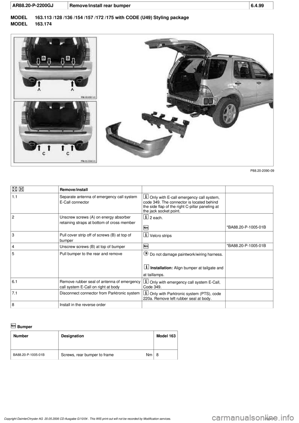
AR88.20-P-2200GJ
Remove/install rear bumper
6.4.99
MODEL
163.113 /128 /136 /154 /157 /172 /175 with CODE (U49) Styling package
MODEL
163.174
P88.20-2090-09
Remove/install
1.1
Separate antenna of emergency call system
E-Call connector
Only with E-call emergency call system,
code 349. The connector is located behind
the side flap of the right C-pillar paneling at
the jack socket point.
2
Unscrew screws (A) on energy absorber
retaining straps at bottom of cross member
2 each.
*BA88.20-P-1005-01B
3
Pull cover strip off of screws (B) at top of
bumper
Velcro strips
4
Unscrew screws (B) at top of bumper
*BA88.20-P-1005-01B
5
Pull bumper to the rear and remove
Do not damage paintwork/wiring harness.
Installation:
Align bumper at tailgate and
at taillamps.
6.1
Remove rubber seal of antenna of emergency
call system E-Call on right at body
Only with emergency call system E-Call,
Code 349.
7.1
Disconnect connector from Parktronic system
Only with Parktronic system (PTS), code
220a. Remove left rubber seal at body.
8
Install in the reverse order
Bumper
Number
Designation
Model 163
BA88.20-P-1005-01B
Screws, rear bumper to frame
Nm
8
Copyright DaimlerChrysler AG 20.05.2006 CD-Ausgabe G/10/04 . This WIS print-out will not be recorde
d by Modification services.
Page 1
Page 1998 of 4133
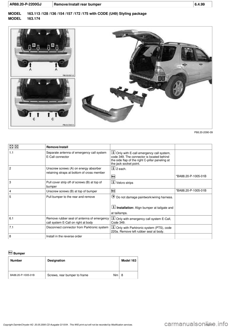
AR88.20-P-2200GJ
Remove/install rear bumper
6.4.99
MODEL
163.113 /128 /136 /154 /157 /172 /175 with CODE (U49) Styling package
MODEL
163.174
P88.20-2090-09
Remove/install
1.1
Separate antenna of emergency call system
E-Call connector
Only with E-call emergency call system,
code 349. The connector is located behind
the side flap of the right C-pillar paneling at
the jack socket point.
2
Unscrew screws (A) on energy absorber
retaining straps at bottom of cross member
2 each.
*BA88.20-P-1005-01B
3
Pull cover strip off of screws (B) at top of
bumper
Velcro strips
4
Unscrew screws (B) at top of bumper
*BA88.20-P-1005-01B
5
Pull bumper to the rear and remove
Do not damage paintwork/wiring harness.
Installation:
Align bumper at tailgate and
at taillamps.
6.1
Remove rubber seal of antenna of emergency
call system E-Call on right at body
Only with emergency call system E-Call,
Code 349.
7.1
Disconnect connector from Parktronic system
Only with Parktronic system (PTS), code
220a. Remove left rubber seal at body.
8
Install in the reverse order
Bumper
Number
Designation
Model 163
BA88.20-P-1005-01B
Screws, rear bumper to frame
Nm
8
Copyright DaimlerChrysler AG 20.05.2006 CD-Ausgabe G/10/04 . This WIS print-out will not be recorde
d by Modification services.
Page 1
Page 2003 of 4133
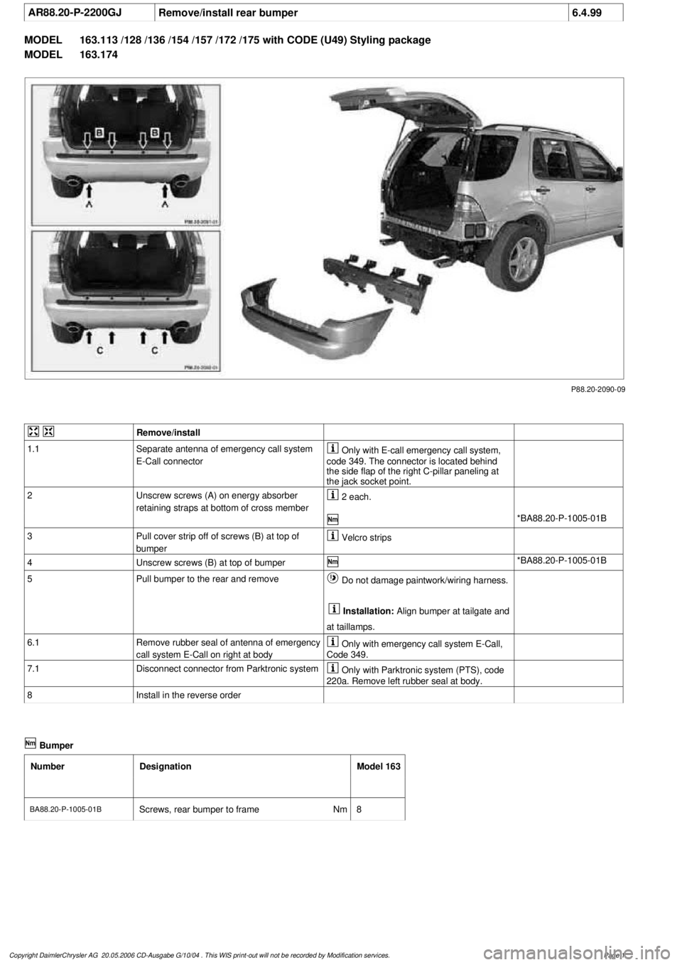
AR88.20-P-2200GJ
Remove/install rear bumper
6.4.99
MODEL
163.113 /128 /136 /154 /157 /172 /175 with CODE (U49) Styling package
MODEL
163.174
P88.20-2090-09
Remove/install
1.1
Separate antenna of emergency call system
E-Call connector
Only with E-call emergency call system,
code 349. The connector is located behind
the side flap of the right C-pillar paneling at
the jack socket point.
2
Unscrew screws (A) on energy absorber
retaining straps at bottom of cross member
2 each.
*BA88.20-P-1005-01B
3
Pull cover strip off of screws (B) at top of
bumper
Velcro strips
4
Unscrew screws (B) at top of bumper
*BA88.20-P-1005-01B
5
Pull bumper to the rear and remove
Do not damage paintwork/wiring harness.
Installation:
Align bumper at tailgate and
at taillamps.
6.1
Remove rubber seal of antenna of emergency
call system E-Call on right at body
Only with emergency call system E-Call,
Code 349.
7.1
Disconnect connector from Parktronic system
Only with Parktronic system (PTS), code
220a. Remove left rubber seal at body.
8
Install in the reverse order
Bumper
Number
Designation
Model 163
BA88.20-P-1005-01B
Screws, rear bumper to frame
Nm
8
Copyright DaimlerChrysler AG 20.05.2006 CD-Ausgabe G/10/04 . This WIS print-out will not be recorde
d by Modification services.
Page 1
Page 2021 of 4133
AR68.20-P-2020GH
Removing and installing rear section of center console
18.5.01
MODEL
163.113 /136 /154 /172 /174 as of 1.9.99 up to 31.8.01
P68.20-2492-06
1
Rear cupholder
2
Screw
3
Center console rear section
4
Tab
Remove, install
1
Open rear cupholder (1), release from center
console and fold down
2
Remove screws (2)
3
Unclip rear section (3) at top (arrows)
*115589035900
4
Release tabs (4) at bottom
Danger of breaking.
5
Pull rear section (3) away from center console
6
Unplug connectors for rear window switches
7
Install in reverse order
Long wedge
115 589 03 59 00
Copyright DaimlerChrysler AG 10.05.2006 CD-Ausgabe G/10/04 . This WIS print-out will not be recorde
d by Modification services.
Page 1
Page 2078 of 4133
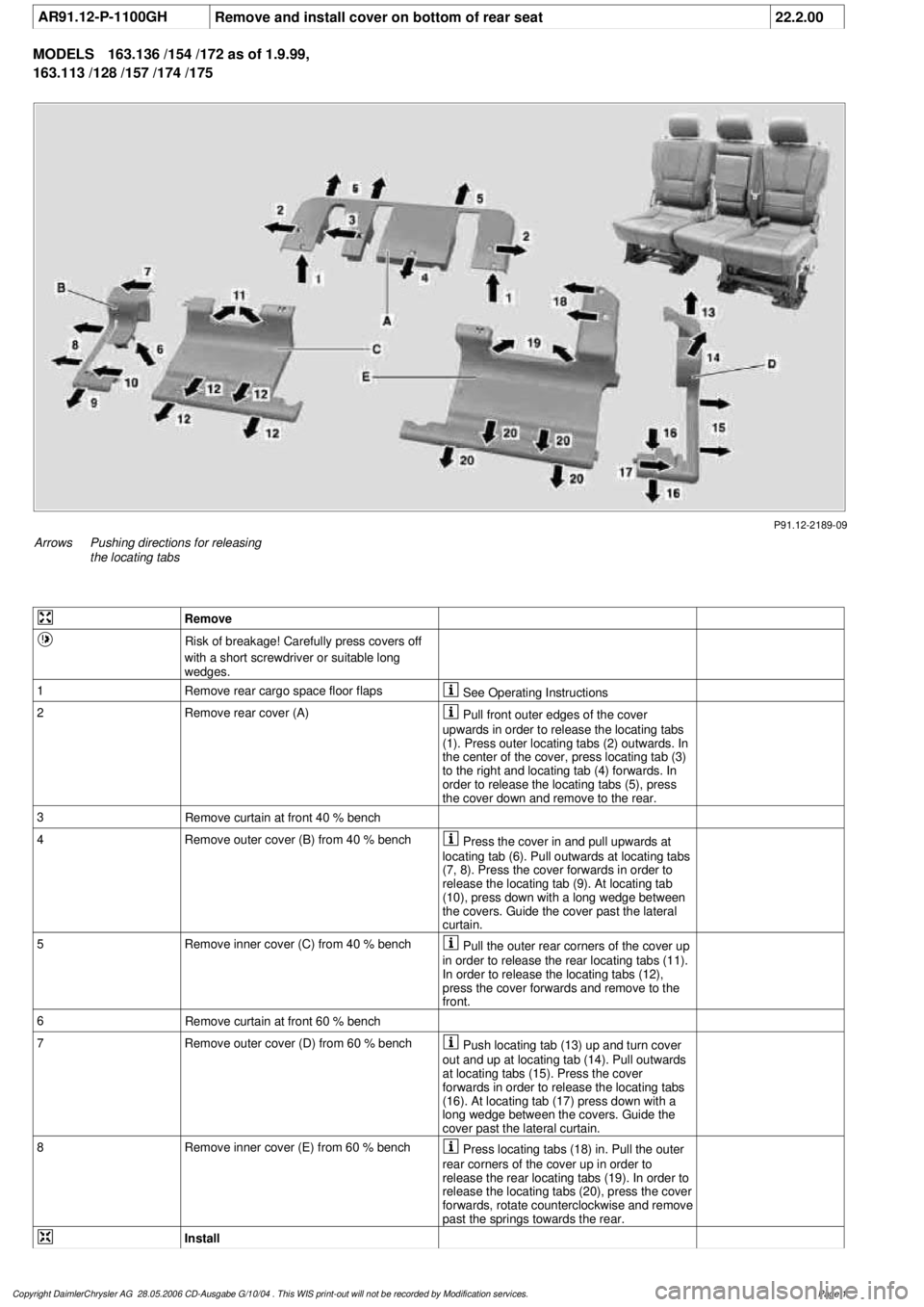
AR91.12-P-1100GH
Remove and install cover on bottom of rear seat
22.2.00
MODELS
163.136 /154 /172 as of 1.9.99,
163.113 /128 /157 /174 /175
P91.12-2189-09
Arrows
Pushing directions for releasing
the locating tabs
Remove
Risk of breakage! Carefully press covers off
with a short screwdriver or suitable long
wedges.
1
Remove rear cargo space floor flaps
See Operating Instructions
2Remove rear cover (A)
Pull front outer edges of the cover
upwards in order to release the locating tabs
(1). Press outer locating tabs (2) outwards. In
the center of the cover, press locating tab (3)
to the right and locating tab (4) forwards. In
order to release the locating tabs (5), press
the cover down and remove to the rear.
3
Remove curtain at front 40 % bench
4
Remove outer cover (B) from 40 % bench
Press the cover in and pull upwards at
locating tab (6). Pull outwards at locating tabs
(7, 8). Press the cover forwards in order to
release the locating tab (9). At locating tab
(10), press down with a long wedge between
the covers. Guide the cover past the lateral
curtain.
5
Remove inner cover (C) from 40 % bench
Pull the outer rear corners of the cover up
in order to release the rear locating tabs (11).
In order to release the locating tabs (12),
press the cover forwards and remove to the
front.
6
Remove curtain at front 60 % bench
7
Remove outer cover (D) from 60 % bench
Push locating tab (13) up and turn cover
out and up at locating tab (14). Pull outwards
at locating tabs (15). Press the cover
forwards in order to release the locating tabs
(16). At locating tab (17) press down with a
long wedge between the covers. Guide the
cover past the lateral curtain.
8
Remove inner cover (E) from 60 % bench
Press locating tabs (18) in. Pull the outer
rear corners of the cover up in order to
release the rear locating tabs (19). In order to
release the locating tabs (20), press the cover
forwards, rotate counterclockwise and remove
past the springs towards the rear.
Install
Copyright DaimlerChrysler AG 28.05.2006 CD-Ausgabe G/10/04 . This WIS print-out will not be recorde
d by Modification services.
Page 1