1997 MERCEDES-BENZ ML350 trunk
[x] Cancel search: trunkPage 1905 of 4133
RETROFITTING TRAFFICSTAR NAVIGATION SYSTEM - AZ82.61-P-0001I
MODEL 163 up to 30.6.99 except CODE (819) 6-disk CD changer in trunk
System illustration
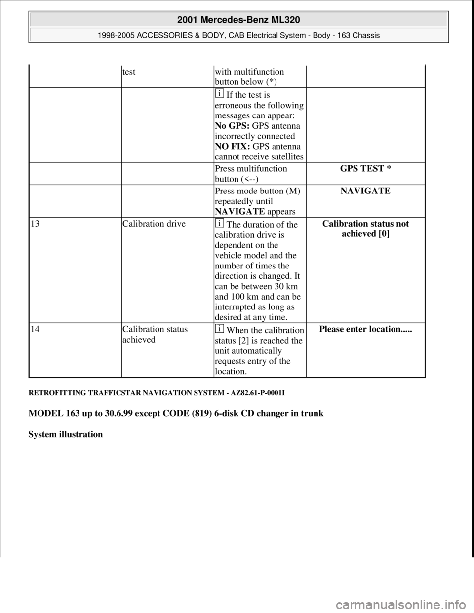
testwith multifunction
button below (*)
If the test is
erroneous the following
messages can appear:
No GPS: GPS antenna
incorrectly connected
NO FIX: GPS antenna
cannot receive satellites
Press multifunction
button (<--)GPS TEST *
Press mode button (M)
repeatedly until
NAVIGATE appearsNAVIGATE
13Calibration drive The duration of the
calibration drive is
dependent on the
vehicle model and the
number of times the
direction is changed. It
can be between 30 km
and 100 km and can be
interrupted as long as
desired at any time.Calibration status not
achieved [0]
14Calibration status
achievedWhen the calibration
status [2] is reached the
unit automatically
requests entry of the
location.Please enter location.....
2001 Mercedes-Benz ML320
1998-2005 ACCESSORIES & BODY, CAB Electrical System - Body - 163 Chassis
me
Saturday, October 02, 2010 3:30:13 PMPage 410 © 2006 Mitchell Repair Information Company, LLC.
Page 1915 of 4133
Seat belts/emergency tensioning retractors
Parts ordering notes
RETROFITTING TELEPHONE CONSOLE - AZ82.70-P-0001-01A
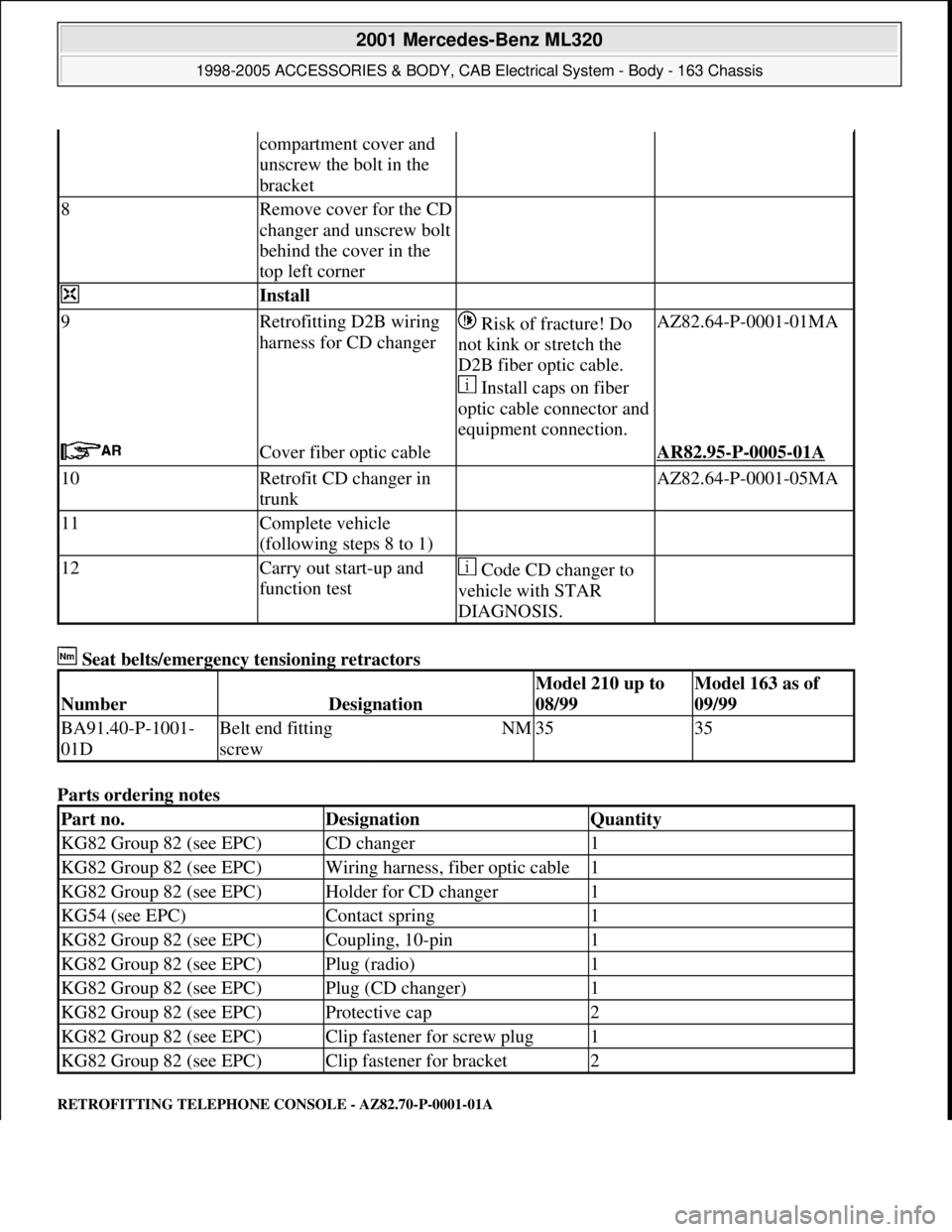
compartment cover and
unscrew the bolt in the
bracket
8Remove cover for the CD
changer and unscrew bolt
behind the cover in the
top left corner
Install
9Retrofitting D2B wiring
harness for CD changer Risk of fracture! Do
not kink or stretch the
D2B fiber optic cable.
Install caps on fiber
optic cable connector and
equipment connection.AZ82.64-P-0001-01MA
Cover fiber optic cable AR82.95-P-0005-01A
10Retrofit CD changer in
trunk AZ82.64-P-0001-05MA
11Complete vehicle
(following steps 8 to 1)
12Carry out start-up and
function test Code CD changer to
vehicle with STAR
DIAGNOSIS.
NumberDesignation
Model 210 up to
08/99Model 163 as of
09/99
BA91.40-P-1001-
01DBelt end fitting
screwNM3535
Part no.DesignationQuantity
KG82 Group 82 (see EPC)CD changer1
KG82 Group 82 (see EPC)Wiring harness, fiber optic cable1
KG82 Group 82 (see EPC)Holder for CD changer1
KG54 (see EPC)Contact spring1
KG82 Group 82 (see EPC)Coupling, 10-pin1
KG82 Group 82 (see EPC)Plug (radio)1
KG82 Group 82 (see EPC)Plug (CD changer)1
KG82 Group 82 (see EPC)Protective cap2
KG82 Group 82 (see EPC)Clip fastener for screw plug1
KG82 Group 82 (see EPC)Clip fastener for bracket2
2001 Mercedes-Benz ML320
1998-2005 ACCESSORIES & BODY, CAB Electrical System - Body - 163 Chassis
me
Saturday, October 02, 2010 3:30:13 PMPage 420 © 2006 Mitchell Repair Information Company, LLC.
Page 2030 of 4133
AR09.41-P-6817MM
Removing and installing charge air cooler
10.11.99
ENGINE
612.963 in MODEL 163.113
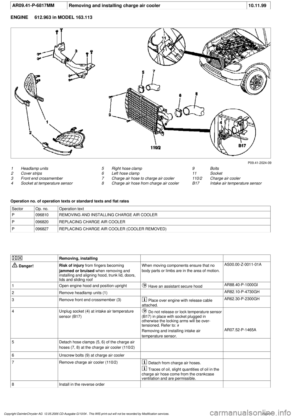
P09.41-2024-09
1
Headlamp units
2
Cover strips
3
Front end crossmember
4
Socket at temperature sensor
9
Bolts
11
Socket
110/2
Charge air cooler
B17
Intake air temperature sensor
5
Right hose clamp
6
Left hose clamp
7
Charge air hose to charge air cooler
8
Charge air hose from charge air cooler
Operation no. of operation texts or standard texts and flat rates
Sector
Op. no.
Operation text
P
096810
REMOVING AND INSTALLING CHARGE AIR COOLER
P
096820
REPLACING CHARGE AIR COOLER
P
096827
REPLACING CHARGE AIR COOLER (COOLER REMOVED)
Removing, installing
Danger!
Risk of injury
from fingers becoming
jammed or bruised
when removing and
installing and aligning hood, trunk lid, doors,
lids and sliding roof
When moving components ensure that no
body parts or limbs are in the area of motion.
AS00.00-Z-0011-01A
1
Open engine hood and position upright
Have an assistant secure hood
AR88.40-P-1000GI
2
Remove headlamp units (1)
AR82.10-P-4730GH
3
Remove front end crossmember (3)
Place over engine with release cable
attached.
AR62.30-P-2300GH
4
Unplug socket (4) at intake air temperature
sensor (B17)
Do not release or lock temperature sensor
(B17) in place with socket plugged in
otherwise the locking arms will be over-
tensioned. Refer to:
#
Removing and installing intake air
temperature sensor.
AR07.52-P-1465A
5
Detach hose clamps (5, 6) of the charge air
hoses (7, 8) at the charge air cooler (110/2)
6
Unscrew bolts (9) at charge air cooler
7
Remove charge air cooler (110/2)
Detach from charge air hoses.
Traces of oil, slight quantities of oil in the
charge air hose come from the crankcase
ventilation and are permissible.
8
Install in the reverse order
Copyright DaimlerChrysler AG 12.05.2006 CD-Ausgabe G/10/04 . This WIS print-out will not be recorde
d by Modification services.
Page 1
Page 2032 of 4133
AR09.41-P-6817MM
Removing and installing charge air cooler
10.11.99
ENGINE
612.963 in MODEL 163.113
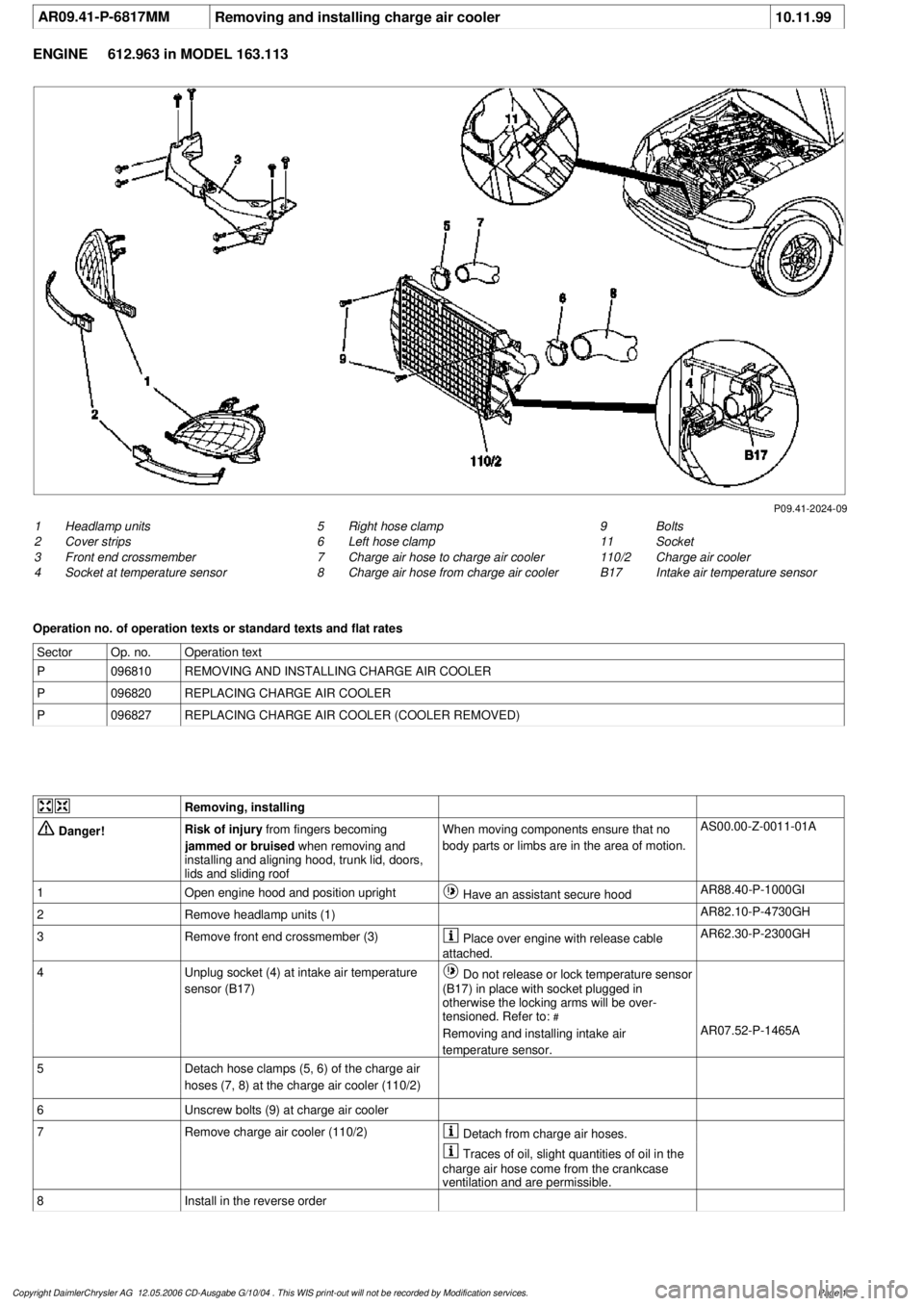
P09.41-2024-09
1
Headlamp units
2
Cover strips
3
Front end crossmember
4
Socket at temperature sensor
9
Bolts
11
Socket
110/2
Charge air cooler
B17
Intake air temperature sensor
5
Right hose clamp
6
Left hose clamp
7
Charge air hose to charge air cooler
8
Charge air hose from charge air cooler
Operation no. of operation texts or standard texts and flat rates
Sector
Op. no.
Operation text
P
096810
REMOVING AND INSTALLING CHARGE AIR COOLER
P
096820
REPLACING CHARGE AIR COOLER
P
096827
REPLACING CHARGE AIR COOLER (COOLER REMOVED)
Removing, installing
Danger!
Risk of injury
from fingers becoming
jammed or bruised
when removing and
installing and aligning hood, trunk lid, doors,
lids and sliding roof
When moving components ensure that no
body parts or limbs are in the area of motion.
AS00.00-Z-0011-01A
1
Open engine hood and position upright
Have an assistant secure hood
AR88.40-P-1000GI
2
Remove headlamp units (1)
AR82.10-P-4730GH
3
Remove front end crossmember (3)
Place over engine with release cable
attached.
AR62.30-P-2300GH
4
Unplug socket (4) at intake air temperature
sensor (B17)
Do not release or lock temperature sensor
(B17) in place with socket plugged in
otherwise the locking arms will be over-
tensioned. Refer to:
#
Removing and installing intake air
temperature sensor.
AR07.52-P-1465A
5
Detach hose clamps (5, 6) of the charge air
hoses (7, 8) at the charge air cooler (110/2)
6
Unscrew bolts (9) at charge air cooler
7
Remove charge air cooler (110/2)
Detach from charge air hoses.
Traces of oil, slight quantities of oil in the
charge air hose come from the crankcase
ventilation and are permissible.
8
Install in the reverse order
Copyright DaimlerChrysler AG 12.05.2006 CD-Ausgabe G/10/04 . This WIS print-out will not be recorde
d by Modification services.
Page 1
Page 2068 of 4133
AR20.00-P-1142M
Drain, pour in coolant
8.11.99
ENGINE
612.963 in MODEL 163.113
P20.20-2083-12
1
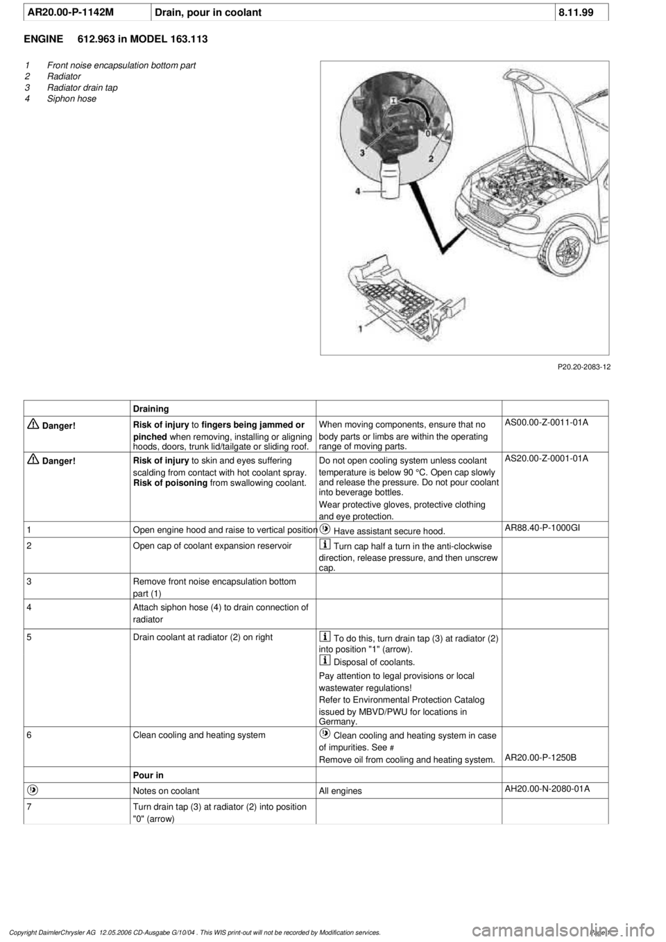
Front noise encapsulation bottom part
2
Radiator
3
Radiator drain tap
4
Siphon hose
Draining
Danger!
Risk of injury
to
fingers being jammed or
pinched
when removing, installing or aligning
hoods, doors, trunk lid/tailgate or sliding roof.
When moving components, ensure that no
body parts or limbs are within the operating
range of moving parts.
AS00.00-Z-0011-01A
Danger!
Risk of injury
to skin and eyes suffering
scalding from contact with hot coolant spray.
Risk of poisoning
from swallowing coolant.
Do not open cooling system unless coolant
temperature is below 90 °C. Open cap slowly
and release the pressure. Do not pour coolant
into beverage bottles.
Wear protective gloves, protective clothing
and eye protection.
AS20.00-Z-0001-01A
1
Open engine hood and raise to vertical position
Have assistant secure hood.
AR88.40-P-1000GI
2
Open cap of coolant expansion reservoir
Turn cap half a turn in the anti-clockwise
direction, release pressure, and then unscrew
cap.
3
Remove front noise encapsulation bottom
part (1)
4
Attach siphon hose (4) to drain connection of
radiator
5
Drain coolant at radiator (2) on right
To do this, turn drain tap (3) at radiator (2)
into position "1" (arrow).
Disposal of coolants.
Pay attention to legal provisions or local
wastewater regulations!
Refer to Environmental Protection Catalog
issued by MBVD/PWU for locations in
Germany.
6
Clean cooling and heating system
Clean cooling and heating system in case
of impurities. See
#
Remove oil from cooling and heating system.
AR20.00-P-1250B
Pour in
Notes on coolant
All engines
AH20.00-N-2080-01A
7
Turn drain tap (3) at radiator (2) into position
"0" (arrow)
Copyright DaimlerChrysler AG 12.05.2006 CD-Ausgabe G/10/04 . This WIS print-out will not be recorde
d by Modification services.
Page 1
Page 2075 of 4133
AR20.00-P-1142M
Drain, pour in coolant
8.11.99
ENGINE
612.963 in MODEL 163.113
P20.20-2083-12
1
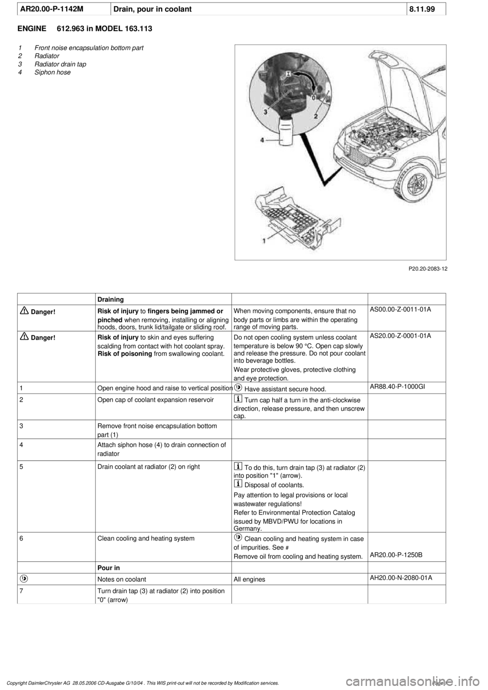
Front noise encapsulation bottom part
2
Radiator
3
Radiator drain tap
4
Siphon hose
Draining
Danger!
Risk of injury
to
fingers being jammed or
pinched
when removing, installing or aligning
hoods, doors, trunk lid/tailgate or sliding roof.
When moving components, ensure that no
body parts or limbs are within the operating
range of moving parts.
AS00.00-Z-0011-01A
Danger!
Risk of injury
to skin and eyes suffering
scalding from contact with hot coolant spray.
Risk of poisoning
from swallowing coolant.
Do not open cooling system unless coolant
temperature is below 90 °C. Open cap slowly
and release the pressure. Do not pour coolant
into beverage bottles.
Wear protective gloves, protective clothing
and eye protection.
AS20.00-Z-0001-01A
1
Open engine hood and raise to vertical position
Have assistant secure hood.
AR88.40-P-1000GI
2
Open cap of coolant expansion reservoir
Turn cap half a turn in the anti-clockwise
direction, release pressure, and then unscrew
cap.
3
Remove front noise encapsulation bottom
part (1)
4
Attach siphon hose (4) to drain connection of
radiator
5
Drain coolant at radiator (2) on right
To do this, turn drain tap (3) at radiator (2)
into position "1" (arrow).
Disposal of coolants.
Pay attention to legal provisions or local
wastewater regulations!
Refer to Environmental Protection Catalog
issued by MBVD/PWU for locations in
Germany.
6
Clean cooling and heating system
Clean cooling and heating system in case
of impurities. See
#
Remove oil from cooling and heating system.
AR20.00-P-1250B
Pour in
Notes on coolant
All engines
AH20.00-N-2080-01A
7
Turn drain tap (3) at radiator (2) into position
"0" (arrow)
Copyright DaimlerChrysler AG 28.05.2006 CD-Ausgabe G/10/04 . This WIS print-out will not be recorde
d by Modification services.
Page 1
Page 2146 of 4133
MISCELLANEOUS
MISCELLANEOUS LOCATION
CONNECTORS
CONNECTORS LOCATION
Parking Brake SwitchOn parking brake support bracket.
Passenger's Seat Belt SwitchIn passenger's seat belt buckle.
Release Switch (BAS)Integral to brake booster.
Right Front Seat Belt Buckle SwitchIn passenger's seat belt buckle.
Rotary Tumbler Trunk Lid MicroswitchPart of tailgate latch assembly.
Stoplight SwitchOn brake pedal support.
ComponentComponent Location
Alarm HornIn left rear corner of engine compartment.
Alarm Siren W/ Auxiliary BatteryIn left rear corner of engine compartment.
Antenna Coil (Left)At left side of rear window, behind trim.
Antenna Coil (Right)At right side of rear window, behind trim.
Antenna SplitterOn right side of liftgate.
Audio AmplifierBehind left side of dash.
Blower Motor Preresistor GroupUnder right side of dash, in blower assembly.
Data Link Connector (DLC)Below left side of dash.
Diagnostic Module (OBD II) Scan Tool ConnectorBelow left side of dash.
Driver's ETR SquibOn base of left "B" pillar, behind trim.
FM/AM AmplifierIn liftgate, behind trim.
Front Passenger ETR SquibOn base of right "B" pillar, behind trim.
Garage Door TransmitterOn front center of roof.
Hands-Free MicrophoneOn front center of roof.
Low Beam Headlight Relay Shorting ClipIn left side of engine compartment, in fuse & relay
box.
Recirculated Air Flap ElementBehind right side of dash.
Transponder CoilTop right side of steering column, on ignition
switch.
ComponentComponent Location
X2/4 (Black, 2-Pin)Behind radio.
X11/4 (Black, 16-Pin)Below left side of dash.
X18 (Red, 28-Pin)Behind center of dash.
X18/1 (Black, 9-Pin)Under tailgate trim.
X18/A_B (Black, 16-Pin)At right kick panel.
X18/2 (1) (White, 10-Pin)At left rear of engine compartment.
X18/2 (2) (4-Pin)At left rear of engine compartment, in E-box.
2001 Mercedes-Benz ML320
2001 MERCEDES-BENZ ML320 & ML430
me
Saturday, October 02, 2010 3:21:17 PMPage 6 © 2006 Mitchell Repair Information Company, LLC.
Page 2215 of 4133
being jammed or squeezed
when removing and
installing or aligning hoods,
doors, trunk lid/tailgate or
sliding roof.ensure that no body parts or
limbs are within the operating
range of moving parts.
1Open engine hoodModel 163.136/154 /172 #A up
to 145272,
Model 163.136 /154 /172 #X up
to 708318AR88.40-P-1000GH
Model 163.136 /154 /172 #A as
of 145273,
Model 163.136 /154 /172 #X
from 708319,
Model
163.113/128 /157 /174 /175AR88.40-P-1000GI
2Disconnect battery ground
line Insulate cable lug of ground
line for protection against
unintentional contact of
disconnected ground line.AR54.10-P-0003A
Notes on batteryAll modelsAH54.10-P-0001-
01A
3Remove air cleaner housing Installation: Apply liquid
lubricant to the mounting
rubbers and to the connection to
the air hose.
Lubricant
*BR00.45-Z-1002-
06A
4.1Remove engine trim panel Engine 112, 113 only.
Pull the engine cover
vertically upwards and detach it
from the cylinder head covers.
5Slacken poly V-belt Do not remove the poly-V-
belt!
Engine 111AR13.22-P-1202A
Engine 603.931/972,
Engine 113.942AR13.22-P-1202B
Engine 113.981/965AR13.22-P-1202BA
6Disconnect electrical line
circuit 30 (B+) (1) and
electrical line circuit 61 (D+)
(2) On engine 112, 113 take off
cover sleeve (4).
*BA15.40-P-1001-
01A
*BA15.40-P-1002-
01A
7Unscrew bolts (3) of the
generator (G2) *BA15.40-P-1003-
01A
8Take out generator (G2)
9Install in the reverse
2001 Mercedes-Benz ML320
1998-2005 ENGINE Electrical System - Engine - 163 Chassis
me
Saturday, October 02, 2010 3:18:54 PMPage 61 © 2006 Mitchell Repair Information Company, LLC.