1997 MERCEDES-BENZ ML350 trunk
[x] Cancel search: trunkPage 2591 of 4133
AR47.20-P-1070M
Removing and installing fuel full-flow filter
24.8.99
ENGINE
612.963 in MODEL 163.113
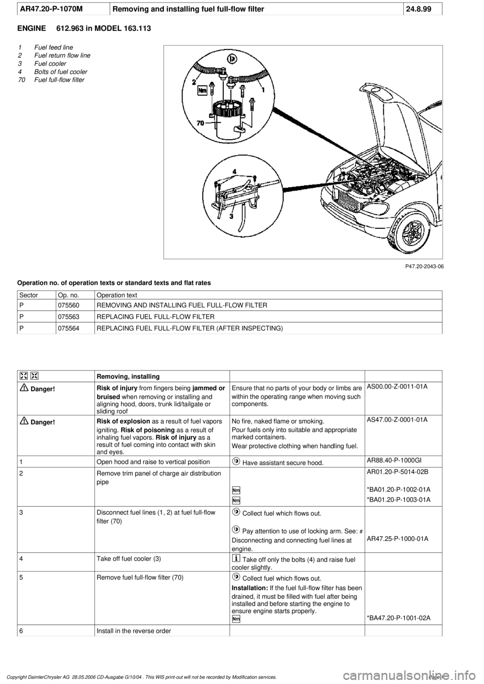
P47.20-2043-06
1
Fuel feed line
2
Fuel return flow line
3
Fuel cooler
4
Bolts of fuel cooler
70
Fuel full-flow filter
Operation no. of operation texts or standard texts and flat rates
Sector
Op. no.
Operation text
P
075560
REMOVING AND INSTALLING FUEL FULL-FLOW FILTER
P
075563
REPLACING FUEL FULL-FLOW FILTER
P
075564
REPLACING FUEL FULL-FLOW FILTER (AFTER INSPECTING)
Removing, installing
Danger!
Risk of injury
from fingers being
jammed or
bruised
when removing or installing and
aligning hood, doors, trunk lid/tailgate or
sliding roof
Ensure that no parts of your body or limbs are
within the operating range when moving such
components.
AS00.00-Z-0011-01A
Danger!
Risk of explosion
as a result of fuel vapors
igniting.
Risk of poisoning
as a result of
inhaling fuel vapors.
Risk of injury
as a
result of fuel coming into contact with skin
and eyes.
No fire, naked flame or smoking.
Pour fuels only into suitable and appropriate
marked containers.
Wear protective clothing when handling fuel.
AS47.00-Z-0001-01A
1
Open hood and raise to vertical position
Have assistant secure hood.
AR88.40-P-1000GI
2
Remove trim panel of charge air distribution
pipe
AR01.20-P-5014-02B
*BA01.20-P-1002-01A
*BA01.20-P-1003-01A
3
Disconnect fuel lines (1, 2) at fuel full-flow
filter (70)
Collect fuel which flows out.
Pay attention to use of locking arm. See:
#
Disconnecting and connecting fuel lines at
engine.
AR47.25-P-1000-01A
4
Take off fuel cooler (3)
Take off only the bolts (4) and raise fuel
cooler slightly.
5
Remove fuel full-flow filter (70)
Collect fuel which flows out.
Installation:
If the fuel full-flow filter has been
drained, it must be filled with fuel after being
installed and before starting the engine to
ensure engine starts properly.
*BA47.20-P-1001-02A
6
Install in the reverse order
Copyright DaimlerChrysler AG 28.05.2006 CD-Ausgabe G/10/04 . This WIS print-out will not be recorde
d by Modification services.
Page 1
Page 2664 of 4133
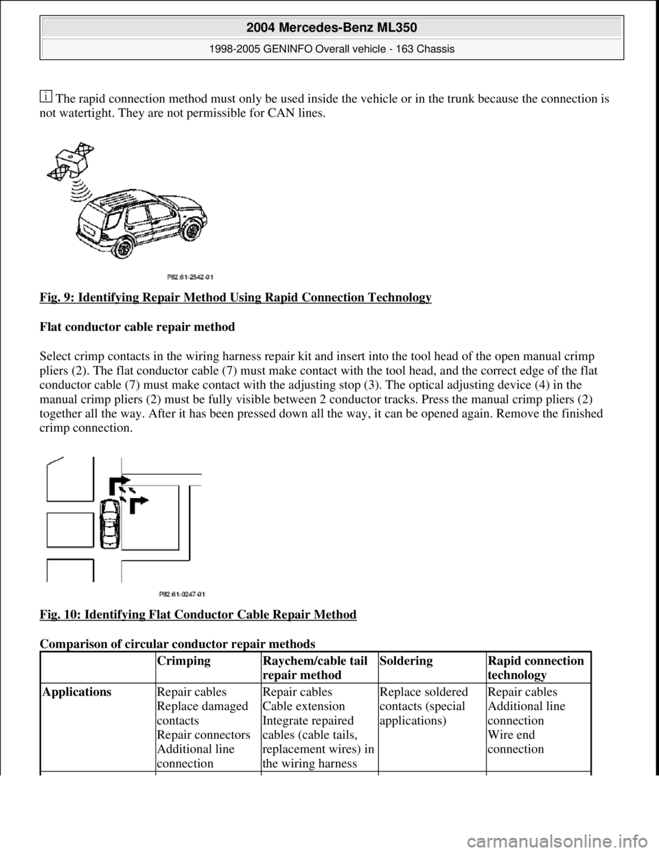
The rapid connection method must only be used inside the vehicle or in the trunk because the connection is
not watertight. They are not permissible for CAN lines.
Fig. 9: Identifying Repair Method Using Rapid Connection Technology
Flat conductor cable repair method
Select crimp contacts in the wiring harness repair kit an d insert into the tool head of the open manual crimp
pliers (2). The flat conductor cable (7) must make contact with the tool head, and the correct edge of the flat
conductor cable (7) must make contac t with the adjusting stop (3). The optical adjusting device (4) in the
manual crimp pliers (2) must be fully visible between 2 conductor tracks. Press the manual crimp pliers (2)
together all the way. After it has been pressed down al l the way, it can be opened again. Remove the finished
crimp connection.
Fig. 10: Identifying Flat Conductor Cable Repair Method
Comparison of circular conductor repair methods
CrimpingRaychem/cable tail
repair methodSolderingRapid connection
technology
Applications Repair cables
Replace damaged
contacts
Repair connectors
Additional line
connectionRepair cables
Cable extension
Integrate repaired
cables (cable tails,
replacement wires) in
the wiring harnessReplace soldered
contacts (special
applications)Repair cables
Additional line
connection
Wire end
connection
2004 Mercedes-Benz ML350
1998-2005 GENINFO Overall vehicle - 163 Chassis
me
Saturday, October 02, 2010 3:47:44 PMPage 19 © 2006 Mitchell Repair Information Company, LLC.
Page 2665 of 4133
ASSESSMENT OF DAMAGE IN WIRING HARNESSES - AH00.19-P-1000-05A
Model 124, 126, 129, 140, 163, 164, 168, 169, 170, 171, 199, 202, 203, 208, 209, 210, 211, 215, 216, 219, 220,
221, 230, 240, 245, 251, 414, 461, 463
Always assess the damage thoroughly before repairing the wiring harnesses.
The following criteria must be observed:
Type of damage:
Damage caused by scorching/overheating, chafing, clamping, crushing, severing, fatigue, corrosion, cable
chewed by an animal, assembly fault.
Cause of damage:
Equipment and
tools required Side cutting pliers
Wire stripper
Crimper with
special die setsSide cutting pliers
Wire stripper
Hot air blower with
special reflector
Raychem connection
Cable tails
Heat shield matSide cutting pliers
Wire stripper
Soldering iron with
accessories
Heat shield mat as
drip protectionSide cutting pliers
Water-pump pliers
Type of contact clampedsolderedsolderedclamped
Heat source NoneHot air gun with
special reflector
(400°C)Soldering iron
(400°C)None
Advantages Quick repair, no
mains power
connection required
Strain relieved by
clamping the
insulation
Simple visual
inspection of
connectionInsulation occurs
automatically
Sealing occurs
automatically
Avoids taut wires by
introducing additional
wiresReplace soldered
contacts (special
applications)No wire stripping
or cutting required
Relatively short
set-up time
No special tool
required
Disadvantages Special crimping
components
requiredMains power
connection required
Accessibility for hot
air gun must be
ensured
Measures for heat
protection requiredExtensive
preparation and
post-working
requiredNo watertight
versions, therefore
only suitable for
use inside the
vehicle or in the
trunk area
Use limited to
certain cable cross-
sections
Not permissible for
CAN lines
2004 Mercedes-Benz ML350
1998-2005 GENINFO Overall vehicle - 163 Chassis
me
Saturday, October 02, 2010 3:47:44 PMPage 20 © 2006 Mitchell Repair Information Company, LLC.
Page 2868 of 4133
Align vehicle between the columns of the lifting platform and position the four support plates at the
lifting platform support points specified by the vehicle manufacturer.
RISK OF ACCIDENT AND INJURY
Please make sure that:
The vehicle is centered lengthwise and crosswise between the lifting platform columns.
The support plates on the lifting platform support points are all positioned at the same height.
The vehicle is first raised a few inches (wheels are still touching the ground) and the position and fit of
the support plates and lift points are checked before raising the vehicle to the full lifted position.
The vehicle is not raised off the lifting platform plates when components are being supported.
If the arms of the lifting platform or the support plates are not positioned properly, or if components of the
vehicle are supported so that the vehicle raises off the platform, then the vehicle can slip off the platform and
cause life-threatening injuries to you or other people.
Before removing axles and assemblies from the vehicle, make sure the vehicle is secured to the platform or that
sand bags are used to balance the vehicle out.
Otherwise the vehicle could tip because of the uneven distribution of weight. This could cause life-threatening
injuries to you or other people.
RISK OF INJURY CAUSED BY FINGERS BEING JAMMED OR PINCHED WHEN REMOVING, INSTALLING OR
ALIGNING HOODS, DOORS, TRUNK LID/ REAR-END DOOR OR SLIDING ROOF. - AS00.00-Z-0011-01A
When moving components, ensure that no body parts or limbs are within the operating range of moving
parts.
Risk of injury
When working on hoods, doors, trunk lids/tailgates and sliding roofs and on their connecting mechanisms,
serious injuries can occur due to cutting, jamming or pinching of body parts like fingers and hands.
Safety instructions/precautions
Be careful when working in hazardous areas.
When moving components, secure the movement area of the mechanism to prevent interference.
Use special tool or other means to ensure safe distance to dangerous areas. NOTE: In Germany, lift platform operators must observe the following regulations and
guidelines: "Berufsgenossenschaftvorschrift (BGV) D29 fur Hebebuhnen" and
the guidelines issued by the lift platform manufacturer. In other countries,
operators must comply with all relevant statutory and accident prevention
regulations.
2004 Mercedes-Benz ML350
1998-2005 GENINFO Overall vehicle - 163 Chassis
me
Saturday, October 02, 2010 3:47:47 PMPage 223 © 2006 Mitchell Repair Information Company, LLC.
Page 2869 of 4133
Wear protective gloves
RISK OF INJURY FROM FINGERS BEING PINCHED OR JAMMED WHEN WORKING ON GAS STRUTS UNDER
PRESSURE - AS00.00-Z-0012-01A
Remove and install gas struts only in relaxed position and on components which have been secured
properly.
Injury hazard
Risk of injury from pinching or crushing when working on gas struts under pressure.
When removing and installing gas struts not in the relaxed position injury can result to body parts from
pinching, crushing or jamming.
Rules of behavior/protective measures
Remove and install gas struts only in relaxed position (pressure or thrust rod completely extended).
Support components held by gas strut (tailgates, doors, trunk lids, seat frame, etc.) in position by suitable
means before removing gas struts.
Replace damaged retaining clips or keepers.
When moving components secure motion area of mechanism against reaching in.
RISK OF INJURY & RICK OF POISONING - AS00.00-Z-0013-01A
Depressurize the hydraulic system completely before starting any work on the system. Wear protective
clothing and eye protection.
Possible hazards
Risk of injury
When disengaging hydraulic lines without first depressurizing the system, dangerous skin or eye injuries may
occur due to the very high pressures (in excess of 200 bar). If hydraulic fluid, particularly central hydraulic fluid
(especially harmful), comes into contact with unprotected skin, this may cause damage to the skin.
Risk of poisoning
If hydraulic fluid is swallowed, this may lead to poisoning symptoms such as headache, giddiness, abdominal
pain, vomiting, diarrhea, cramps and unconsciousness.
Protective measures/guidelines
When commencing work on hydraulic systems, these must be depressurized; the system must be drained
if necessary.
Do not pour hydraulic fluid into beverage containers.
2004 Mercedes-Benz ML350
1998-2005 GENINFO Overall vehicle - 163 Chassis
me
Saturday, October 02, 2010 3:47:47 PMPage 224 © 2006 Mitchell Repair Information Company, LLC.
Page 2878 of 4133
running engine or drive
train.
Risk of injury. Moving parts
can pinch, crush or, in
extreme cases even sever
extremities.MODEL allAS00.00-Z-0009-01A
Risk of injury caused by
fingers being jammed or
pinched when removing,
installing or aligning hoods,
doors, trunk lid/rear-end
door or sliding roof.MODEL allAS00.00-Z-0011-01A
Risk of injury from fingers
being pinched or jammed
when working on gas struts
under pressureMODEL allAS00.00-Z-0012-01A
Risk of injury to skin or
eyes from hydraulic fluid
spraying out under pressure.
Risk of poisoning from
swallowing hydraulic fluid.MODEL allAS00.00-Z-0013-01A
Risk of injury. Rubber
mounts and bearing parts
can suddenly come loose
during installation/ removal
and shoot wildly through
the air.MODEL allAS00.00-Z-0014-01A
Risk of explosion from
pressurized spray cansMODEL 100, 107, 108,
109, 111, 112, 113, 114,
115, 116, 123, 124, 126,
129, 140, 163, 168, 170,
201, 202, 208, 210, 215,
216, 220, 221, 251 ...AS00.00-Z-0015-01A
Risk of poisoning caused by
inhaling vapors or
swallowing adhesive. Risk
of injury caused by glue
coming into contact with
skin and eyesMODEL 163, 169, 199,
204, 209, 211, 215, 216,
219, 221, 240, 245, 397,
461, 463, 613, 638, 639,
671, 684, 901, 902, 903,
904 ...AS00.00-Z-0016-01A
Injury hazard of cutting or
scraping on sharp vehicle
partsMODEL allAS00.00-Z-0017-01A
Risk of explosion caused by
escaping natural gas or an
overheated compressed-gas
tanks when working on MODEL 901, 902, 903,
904, 957.AS00.00-Z-0018-01A
2004 Mercedes-Benz ML350
1998-2005 GENINFO Overall vehicle - 163 Chassis
me
Saturday, October 02, 2010 3:47:48 PMPage 233 © 2006 Mitchell Repair Information Company, LLC.
Page 3193 of 4133
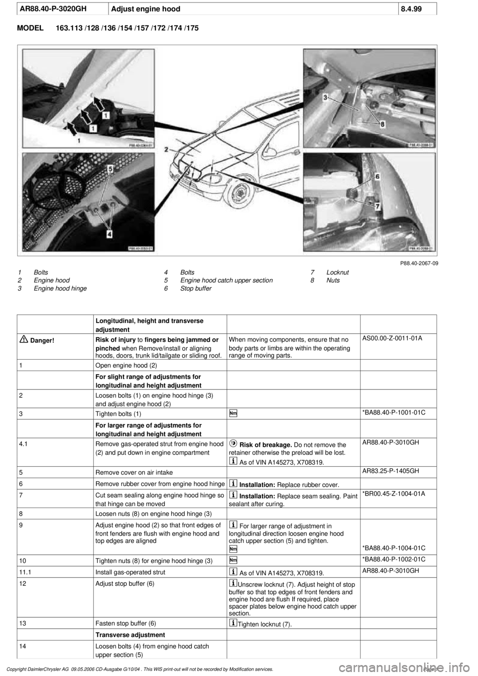
AR88.40-P-3020GH
Adjust engine hood
8.4.99
MODEL
163.113 /128 /136 /154 /157 /172 /174 /175
P88.40-2067-09
1
Bolts
2
Engine hood
3
Engine hood hinge
7
Locknut
8
Nuts
4
Bolts
5
Engine hood catch upper section
6
Stop buffer
Longitudinal, height and transverse
adjustment
Danger!
Risk of injury
to
fingers being jammed or
pinched
when Remove/install or aligning
hoods, doors, trunk lid/tailgate or sliding roof.
When moving components, ensure that no
body parts or limbs are within the operating
range of moving parts.
AS00.00-Z-0011-01A
1
Open engine hood (2)
For slight range of adjustments for
longitudinal and height adjustment
2
Loosen bolts (1) on engine hood hinge (3)
and adjust engine hood (2)
3
Tighten bolts (1)
*BA88.40-P-1001-01C
For larger range of adjustments for
longitudinal and height adjustment
4.1
Remove gas-operated strut from engine hood
(2) and put down in engine compartment
Risk of breakage. Do not remove the
retainer otherwise the preload will be lost.
AR88.40-P-3010GH
As of VIN A145273, X708319.
5
Remove cover on air intake
AR83.25-P-1405GH
6
Remove rubber cover from engine hood hinge
Installation:
Replace rubber cover.
7
Cut seam sealing along engine hood hinge so
that hinge can be moved
Installation:
Replace seam sealing. Paint
sealant after curing.
*BR00.45-Z-1004-01A
8
Loosen nuts (8) on engine hood hinge (3)
9
Adjust engine hood (2) so that front edges of
front fenders are flush with engine hood and
top edges are aligned
For larger range of adjustment in
longitudinal direction loosen engine hood
catch upper section (5) and tighten.
*BA88.40-P-1004-01C
10
Tighten nuts (8) for engine hood hinge (3)
*BA88.40-P-1002-01C
11.1
Install gas-operated strut
As of VIN A145273, X708319.
AR88.40-P-3010GH
12
Adjust stop buffer (6)
Unscrew locknut (7). Adjust height of stop
buffer so that top edges of front fenders and
engine hood are flush If required, place
spacer plates below engine hood catch upper
section.
13
Fasten stop buffer (6)
Tighten locknut (7).
Transverse adjustment
14
Loosen bolts (4) from engine hood catch
upper section (5)
Copyright DaimlerChrysler AG 09.05.2006 CD-Ausgabe G/10/04 . This WIS print-out will not be recorde
d by Modification services.
Page 1
Page 3195 of 4133
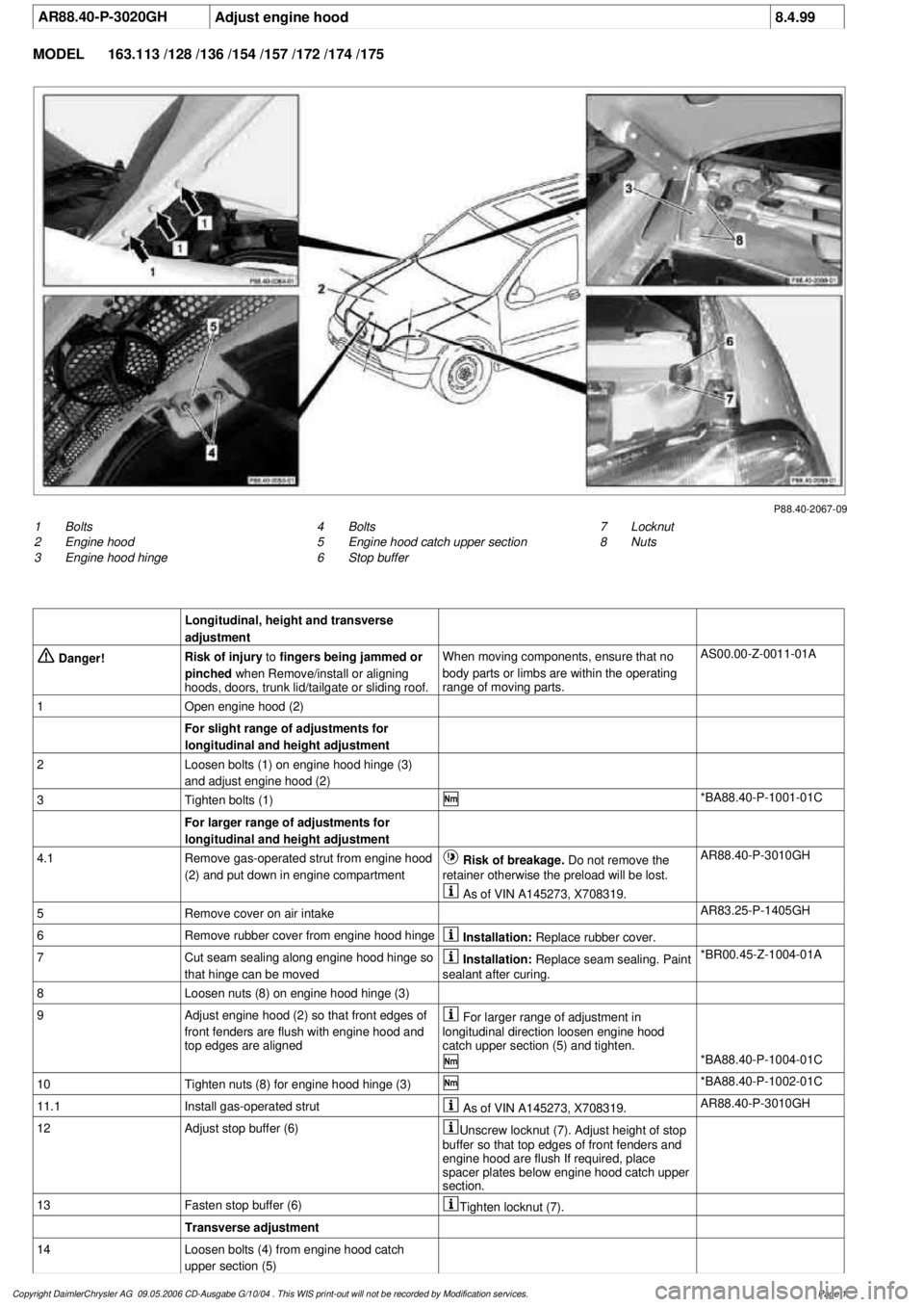
AR88.40-P-3020GH
Adjust engine hood
8.4.99
MODEL
163.113 /128 /136 /154 /157 /172 /174 /175
P88.40-2067-09
1
Bolts
2
Engine hood
3
Engine hood hinge
7
Locknut
8
Nuts
4
Bolts
5
Engine hood catch upper section
6
Stop buffer
Longitudinal, height and transverse
adjustment
Danger!
Risk of injury
to
fingers being jammed or
pinched
when Remove/install or aligning
hoods, doors, trunk lid/tailgate or sliding roof.
When moving components, ensure that no
body parts or limbs are within the operating
range of moving parts.
AS00.00-Z-0011-01A
1
Open engine hood (2)
For slight range of adjustments for
longitudinal and height adjustment
2
Loosen bolts (1) on engine hood hinge (3)
and adjust engine hood (2)
3
Tighten bolts (1)
*BA88.40-P-1001-01C
For larger range of adjustments for
longitudinal and height adjustment
4.1
Remove gas-operated strut from engine hood
(2) and put down in engine compartment
Risk of breakage. Do not remove the
retainer otherwise the preload will be lost.
AR88.40-P-3010GH
As of VIN A145273, X708319.
5
Remove cover on air intake
AR83.25-P-1405GH
6
Remove rubber cover from engine hood hinge
Installation:
Replace rubber cover.
7
Cut seam sealing along engine hood hinge so
that hinge can be moved
Installation:
Replace seam sealing. Paint
sealant after curing.
*BR00.45-Z-1004-01A
8
Loosen nuts (8) on engine hood hinge (3)
9
Adjust engine hood (2) so that front edges of
front fenders are flush with engine hood and
top edges are aligned
For larger range of adjustment in
longitudinal direction loosen engine hood
catch upper section (5) and tighten.
*BA88.40-P-1004-01C
10
Tighten nuts (8) for engine hood hinge (3)
*BA88.40-P-1002-01C
11.1
Install gas-operated strut
As of VIN A145273, X708319.
AR88.40-P-3010GH
12
Adjust stop buffer (6)
Unscrew locknut (7). Adjust height of stop
buffer so that top edges of front fenders and
engine hood are flush If required, place
spacer plates below engine hood catch upper
section.
13
Fasten stop buffer (6)
Tighten locknut (7).
Transverse adjustment
14
Loosen bolts (4) from engine hood catch
upper section (5)
Copyright DaimlerChrysler AG 09.05.2006 CD-Ausgabe G/10/04 . This WIS print-out will not be recorde
d by Modification services.
Page 1