1997 MERCEDES-BENZ ML350 trunk
[x] Cancel search: trunkPage 1505 of 4133
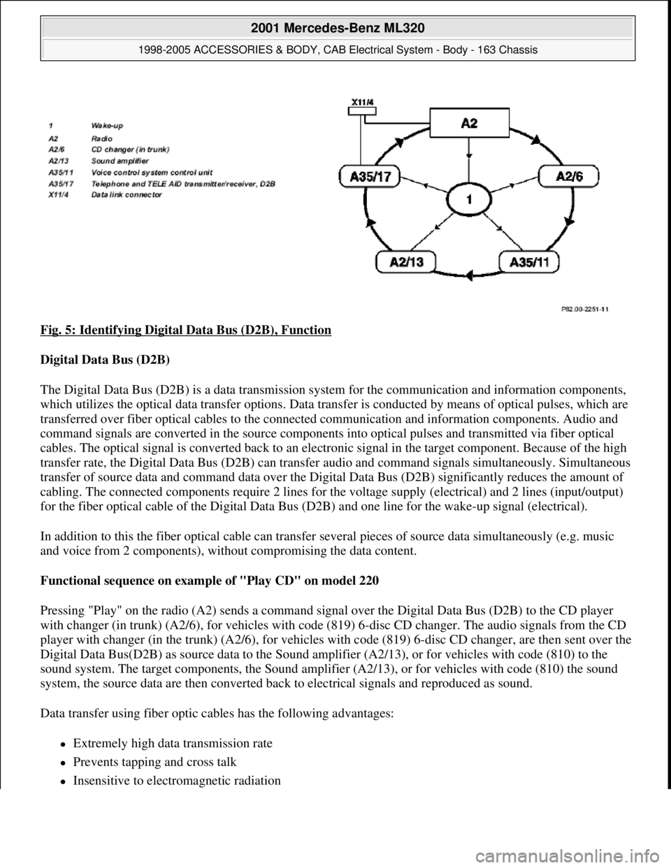
Fig. 5: Identifying Digital Data Bus (D2B), Function
Digital Data Bus (D2B)
The Digital Data Bus (D2B) is a data transmission system for the communication and information components,
which utilizes the optical data transfer options. Data transfer is conducted by means of optical pulses, which are
transferred over fiber optical cables to the connected communication and information components. Audio and
command signals are converted in the source components into optical pulses and transmitted via fiber optical
cables. The optical signal is converted back to an electronic signal in the target component. Because of the high
transfer rate, the Digital Data Bus (D2B) can transfer audio and command signals simultaneously. Simultaneous
transfer of source data and command data over the Digital Data Bus (D2B) significantly reduces the amount of
cabling. The connected components require 2 lines for the voltage supply (electrical) and 2 lines (input/output)
for the fiber optical cable of the Digital Data Bus (D2B) and one line for the wake-up signal (electrical).
In addition to this the fiber optical cable can transfer several pieces of source data simultaneously (e.g. music
and voice from 2 components), without compromising the data content.
Functional sequence on example of "Play CD" on model 220
Pressing "Play" on the radio (A2) sends a command signal over the Digital Data Bus (D2B) to the CD player
with changer (in trunk) (A2/6), for vehicles with code (819) 6-disc CD changer. The audio signals from the CD
player with changer (in the trunk) (A2/6), for vehicles with code (819) 6-disc CD changer, are then sent over the
Digital Data Bus(D2B) as source data to the Sound amplifier (A2/13), or for vehicles with code (810) to the
sound system. The target components, the Sound amplifier (A2/13), or for vehicles with code (810) the sound
system, the source data are then converted back to electrical signals and reproduced as sound.
Data transfer using fiber optic cables has the following advantages:
Extremely high data transmission rate
Prevents tapping and cross talk
Insensitive to electromagnetic radiation
2001 Mercedes-Benz ML320
1998-2005 ACCESSORIES & BODY, CAB Electrical System - Body - 163 Chassis
me
Saturday, October 02, 2010 3:30:04 PMPage 10 © 2006 Mitchell Repair Information Company, LLC.
Page 1506 of 4133
Short-circuit resistance
Zero potential connection of components
No oxidation
Low weight of fiber optical cable
Minimum diameter of wiring harness
The digital data bus (D2B) has a closed ring structure. The communication and data components are arranged
here in a distributor line (in-series circuit). This arrangement is type specific and is illustrated by way of an
example on model 220 as follows:
Radio (A2)
CD player with changer (in trunk) (A2/6), with code (819) 6-disc CD changer
Sound amplifier (A2/13), with code (810) Sound System
Voice control system control unit (A35/11), with code (813) voice control system (VCS)
Telephone and TELE AID transmitter/receiver, D2B (A35/17), with code (855) TELE AID
Data transfer is conducted here in one direction only, i.e. the optical pulses for the voice control system control
unit (A35/11), for vehicles with code (813) voice control system (VCS), on model 220 pass through all
components connected to the ring, before arriving at the target components.
When the system is first put into operation, a system test is performed. In doing so the individual components
and their sequence in the ring structure of the Digital Data Bus (D2B) are registered by the component with the
master function.
A type-specific sequence is stored ex-factory. In turn, the storing of a sequence ex-factory means: if the radio
(A2) is taken from one model series and installed into another one, then during a system test the different
sequence of the components and an error message are filed in the diagnostic trouble code memory.
An error message is also filed if the radio (A2) is exchanged within a model series with different equipment
components. The system goes to the operational state regardless of the error message. STAR DIAGNOSIS
enables the sequence of the components to be subsequently altered in the Digital Data Bus (D2B).
The Digital Data Bus (D2B) is diagnosis capable via the data link connector (X11/4), except for models 129
and 202.
The operating principle of the Digital Data Bus (D2B) is the same for all model series; all that changes is the
sequence of components depending on the national version and equipment specification.
TABLE OF CONTENTS, FUNCTION DESCRIPTION OF DIGITAL DATA BUS (D2B) - GF82.00-P-0999ZZ
MODEL 129 as of 1.6.98, 163, 168 as of 1.9.98, 170, 202 as of 1.6.98, 203, 208, 210 as of 1.6.98, 215, 220
Data transfer, function GF82.00-P-2000A
2001 Mercedes-Benz ML320
1998-2005 ACCESSORIES & BODY, CAB Electrical System - Body - 163 Chassis
me
Saturday, October 02, 2010 3:30:04 PMPage 11 © 2006 Mitchell Repair Information Company, LLC.
Page 1560 of 4133
The radio and navigation module (A2/56)has various optional possibilities for the CD player mode.
CD mode with single CD drive (optional)
The radio and navigation module (A2/56) has an integrated CD drive as an option (code 818) intended for
playing audio CD's . If the radio and navigation module (A2/56) is equipped with a CD drive for navigation
(Code 357) as an option, it is also possible to play audio CD's . (However, during the navigation mode it is not
possible to play audio CD's Opening the operating and display module "(Open " button) allows access to the
CC slot and CD slot.
CD changer mode (with code 819)
The CD player with changer (A2/6) is actuated by the radio and navigation module (A2/56) .
The control signals and audio data from the CD player with changer (in trunk) (A2/6) are transmitted via the
digital data bus (D2B ). The changer is actuated by pressing the "CD" button twice . (When single CD drive is
installed).
Insert only 12 cm CD's into the CD player with changer (in trunk) (A2/6) , also do not use 8 cm CD
adapter .
On sound system (code 810) the sound amplifier (A2/13) takes over final amplification of the audio signals.
The signals between the radio and navigation module (A2/56) and sound amplifier (A2/13) are transmitted
via the digital data bus (D2B ).
The amplified signals are output by the vehicle loudspeaker system.
If the vehicle is equipped with sound amplifier (A2/13) the radio and navigation module (A2/56) should
be coded correspondingly with STAR diagnosis, otherwise malfunctions can occur when reproducing audio
signals.
When a magazine is inserted in the CD changer it is checked and a table of contents is made up. When the test
is completed the system automatically switches over to the playback mode and starts with the first title or next
possible compact disc.
If the system switches over to the CD mode before the test is completed the system starts playback of the CD
which was presently being checked.
The radio and navigation module (A2/56) offers the following functions in combination with the CD player
with changer (in trunk) (A2/6) and/or single CD drive :
Scan function
When the multifunction " Scan " key is pressed each title on the current CD is played for approx. 8 s .
The function is terminated b
y pressing the multifunction " Scan" key again.
2001 Mercedes-Benz ML320
1998-2005 ACCESSORIES & BODY, CAB Electrical System - Body - 163 Chassis
me
Saturday, October 02, 2010 3:30:05 PMPage 65 © 2006 Mitchell Repair Information Company, LLC.
Page 1616 of 4133
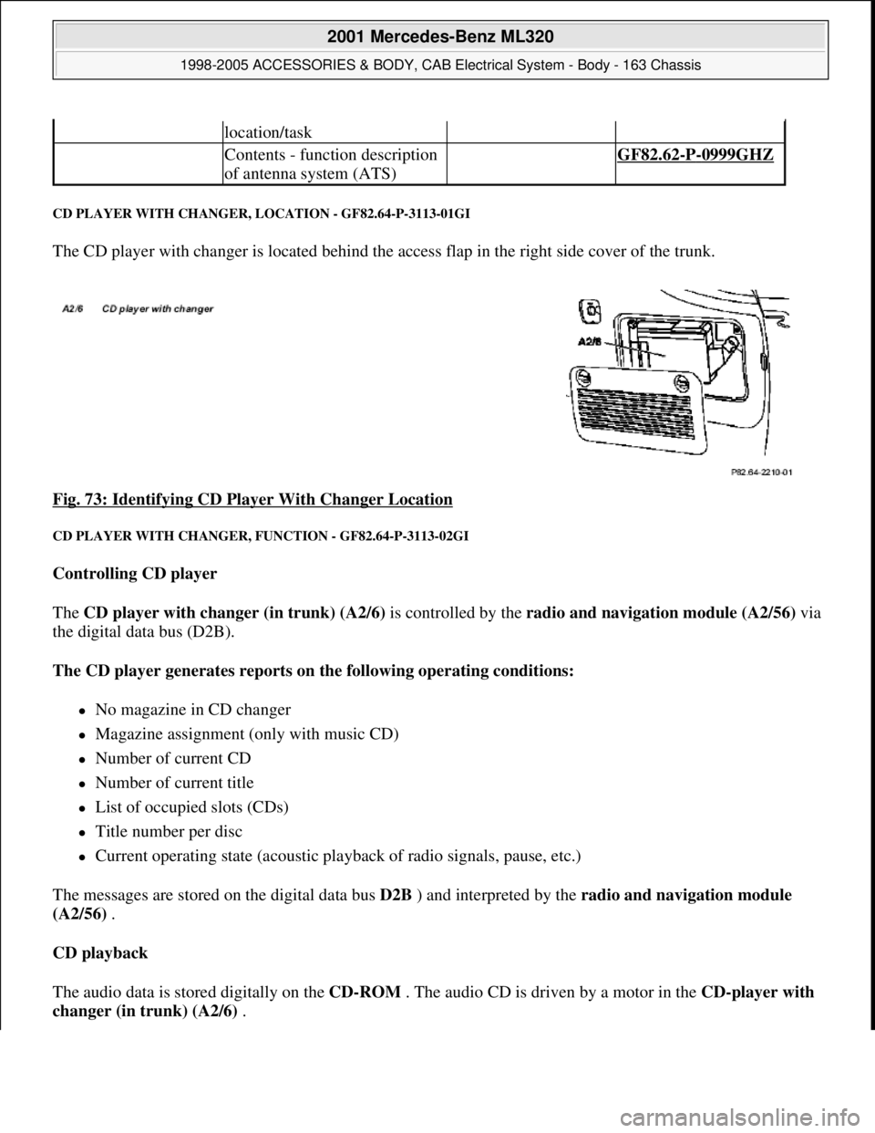
CD PLAYER WITH CHANGER, LOCATION - GF82.64-P-3113-01GI
The CD player with changer is located behind the access flap in the right side cover of the trunk.
Fig. 73: Identifying CD Player With Changer Location
CD PLAYER WITH CHANGER, FUNCTION - GF82.64-P-3113-02GI
Controlling CD player
The CD player with changer (in trunk) (A2/6) is controlled by the radio and navigation module (A2/56)via
the digital data bus (D2B).
The CD player generates reports on the following operating conditions:
No magazine in CD changer
Magazine assignment (only with music CD)
Number of current CD
Number of current title
List of occupied slots (CDs)
Title number per disc
Current operating state (acoustic playback of radio signals, pause, etc.)
The messages are stored on the digital data bus D2B ) and interpreted by the radio and navigation module
(A2/56) .
CD playback
The audio data is stored digitally on the CD-ROM . The audio CD is driven by a motor in the CD-player with
changer (in trunk) (A2/6) .
location/task
Contents - function description
of antenna system (ATS) GF82.62-P-0999GHZ
2001 Mercedes-Benz ML320
1998-2005 ACCESSORIES & BODY, CAB Electrical System - Body - 163 Chassis
me
Saturday, October 02, 2010 3:30:06 PMPage 121 © 2006 Mitchell Repair Information Company, LLC.
Page 1617 of 4133
The laser-optical device scans the non-labeled side of the rotating CDwithout making contact and converts the
digital optical signals into electrical signals. Small interruptions in the data flow of the laser optics caused by
scratches or contamination on the audio CD are compensated by the D/A converter supplementing the missing
values .
The electrical signals are then decoded in the CD player with changer (in trunk) (A2/6) and transmitted via
the digital data bus ( D2B ) to the radio and navigation module (A2/56) via the audio signal processing or
when the sound amplifier (A2/13) (code 810) is installed to the loudspeakers.
Jumps and interruptions during playback
On bad roads or in the event of heavy vibrations , jumps and interruptions can occur during playback. In
such cases do not start CD mode until better road conditions are present.
In the event of wet weather conditions and strong deviations in the ambient temperatures moisture can collect in
the CD player housing (condensation formation). This could also lead to malfunctions in the playback. In such
cases provide for sufficient ventilation of the CD player and the trunk.
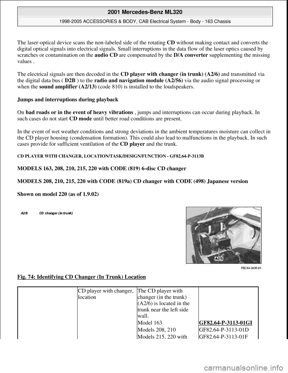
CD PLAYER WITH CHANGER, LOCATION/TASK/DESIGN/FUNCTION - GF82.64-P-3113B
MODELS 163, 208, 210, 215, 220 with CODE (819) 6-disc CD changer
MODELS 208, 210, 215, 220 with CODE (819a) CD changer with CODE (498) Japanese version
Shown on model 220 (as of 1.9.02)
Fig. 74: Identifying CD Changer (In Trunk) Location
CD player with changer,
locationThe CD player with
changer (in the trunk)
(A2/6) is located in the
trunk near the left side
wall.
Model 163GF82.64-P-3113-01GI
Models 208, 210GF82.64-P-3113-01D
Models 215, 220 with GF82.64-P-3113-01F
2001 Mercedes-Benz ML320
1998-2005 ACCESSORIES & BODY, CAB Electrical System - Body - 163 Chassis
me
Saturday, October 02, 2010 3:30:06 PMPage 122 © 2006 Mitchell Repair Information Company, LLC.
Page 1618 of 4133
CD PLAYER WITH CHANGER, LOCATION/PURPOSE/DESIGN/FUNCTION - GF82.64-P-3113GI
MODEL 163 with CODE (522) Modular control system (MCS) radio USA with CODE (357) Navigation
system - additional unit with CODE (818b) Single CD player - additional unit with CODE (819) 6-disk
CD changer in trunk with CODE (491) U.S. version
code 498
Models 215, 220 without
code 498GF82.64-P-3113-01E
CD player with changer,
purposePlaying audio
compact discs (CD)
Changing CDs
contained in the
magazine
CD player with changer,
design6-slot CD changer
magazine
only: 12-slot
CD changer
magazine
Digital Data Bus
(D2B) interface
The factory planned
installation position for
the CD changer is vertical,
whereby other installation
positions are possible by
adaptation of the spring
locations.
CD player with changer,
functionModels 208, 210GF82.64-P-3113-02C
Model 215, 220GF82.64-P-3113-02B
2001 Mercedes-Benz ML320
1998-2005 ACCESSORIES & BODY, CAB Electrical System - Body - 163 Chassis
me
Saturday, October 02, 2010 3:30:06 PMPage 123 © 2006 Mitchell Repair Information Company, LLC.
Page 1625 of 4133
MODULAR CONTROL SYSTEM (MCS), FUNCTION - GF82.85-P-0011GI
MODEL 163 as of 1.9.01 with CODE (522) Modular control system (MCS) radio USA with CODE (357)
Navigation system - additional unit with CODE (818b) Single CD player - additional unit with CODE
(819) 6-disk CD changer in trunk with CODE (491) U.S. version
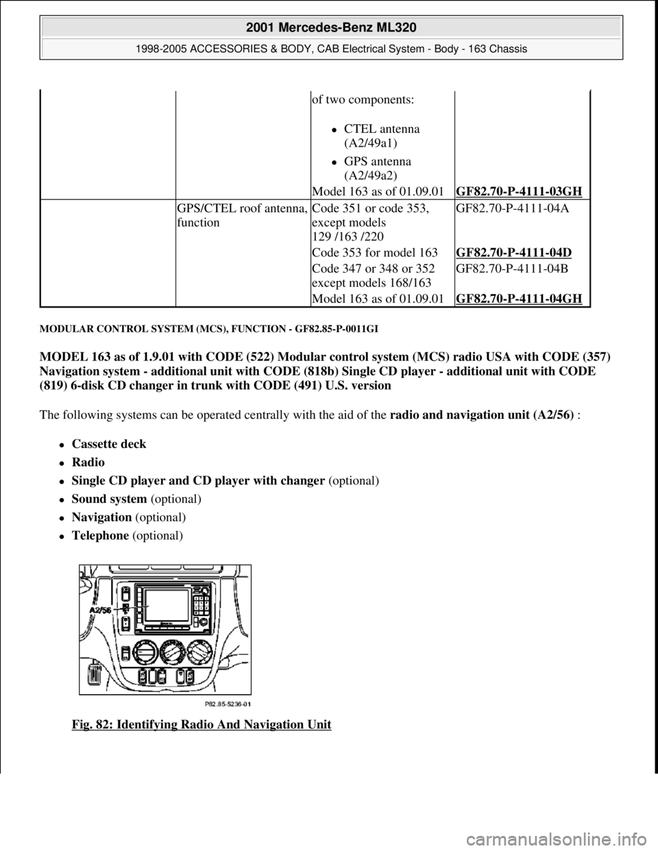
The following systems can be operated centrally with the aid of the radio and navigation unit (A2/56) :
Cassette deck
Radio
Single CD player and CD player with changer (optional)
Sound system (optional)
Navigation (optional)
Telephone (optional)
Fig. 82: Identifying Radio And Navigation Unit
of two components:
CTEL antenna
(A2/49a1)
GPS antenna
(A2/49a2)
Model 163 as of 01.09.01GF82.70-P-4111-03GH
GPS/CTEL roof antenna,
functionCode 351 or code 353,
except models
129 /163 /220GF82.70-P-4111-04A
Code 353 for model 163GF82.70-P-4111-04D
Code 347 or 348 or 352
except models 168/163GF82.70-P-4111-04B
Model 163 as of 01.09.01GF82.70-P-4111-04GH
2001 Mercedes-Benz ML320
1998-2005 ACCESSORIES & BODY, CAB Electrical System - Body - 163 Chassis
me
Saturday, October 02, 2010 3:30:06 PMPage 130 © 2006 Mitchell Repair Information Company, LLC.
Page 1654 of 4133
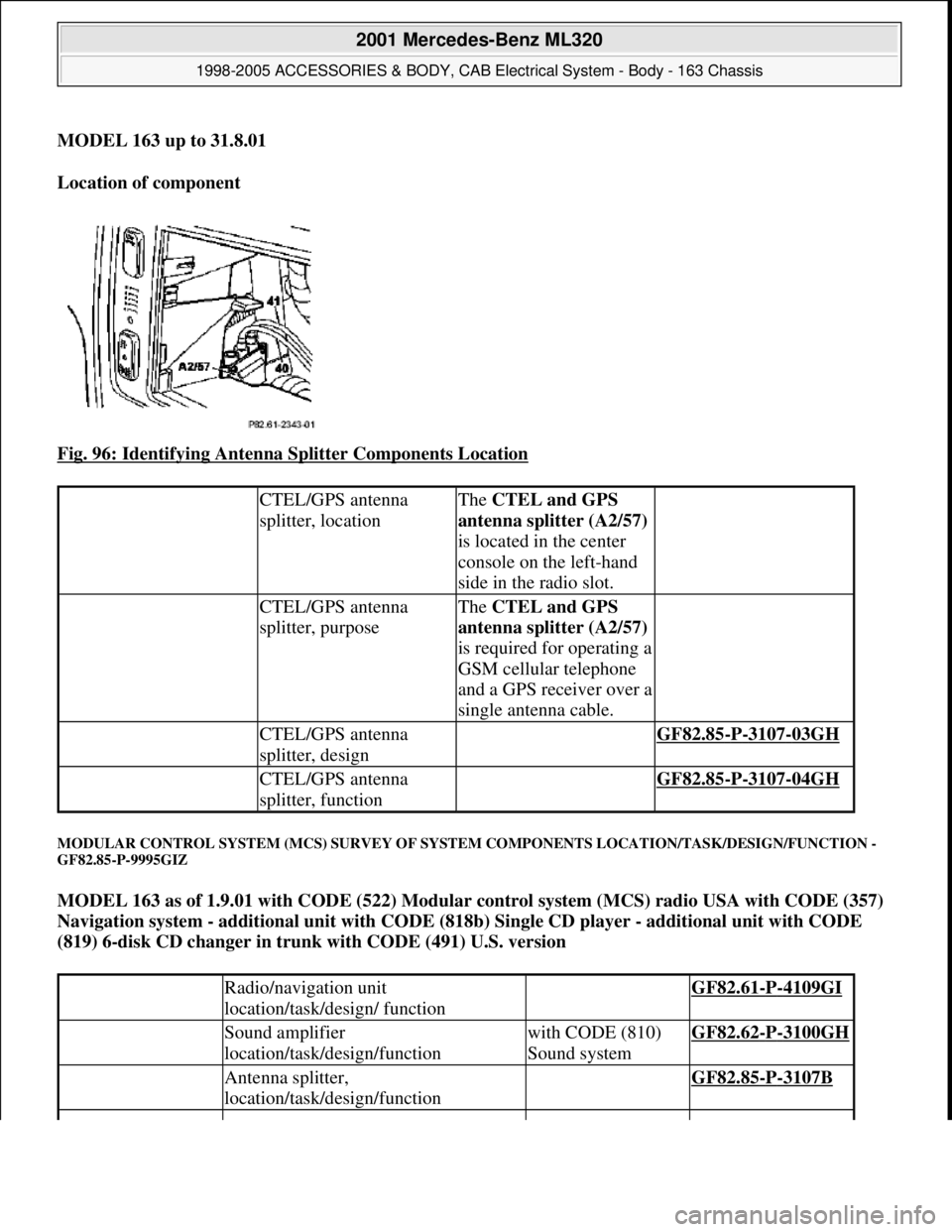
MODEL 163 up to 31.8.01
Location of component
Fig. 96: Identifying Antenna Splitter Components Location
MODULAR CONTROL SYSTEM (MCS) SURVEY OF SYSTEM COMPONENTS LOCATION/TASK/DESIGN/FUNCTION -
GF82.85-P-9995GIZ
MODEL 163 as of 1.9.01 with CODE (522) Modular control system (MCS) radio USA with CODE (357)
Navigation system - additional unit with CODE (818b) Single CD player - additional unit with CODE
(819) 6-disk CD changer in trunk with CODE (491) U.S. version
CTEL/GPS antenna
splitter, locationThe CTEL and GPS
antenna splitter (A2/57)
is located in the center
console on the left-hand
side in the radio slot.
CTEL/GPS antenna
splitter, purposeThe CTEL and GPS
antenna splitter (A2/57)
is required for operating a
GSM cellular telephone
and a GPS receiver over a
single antenna cable.
CTEL/GPS antenna
splitter, design GF82.85-P-3107-03GH
CTEL/GPS antenna
splitter, function GF82.85-P-3107-04GH
Radio/navigation unit
location/task/design/ function GF82.61-P-4109GI
Sound amplifier
location/task/design/functionwith CODE (810)
Sound systemGF82.62-P-3100GH
Antenna splitter,
location/task/design/function GF82.85-P-3107B
2001 Mercedes-Benz ML320
1998-2005 ACCESSORIES & BODY, CAB Electrical System - Body - 163 Chassis
me
Saturday, October 02, 2010 3:30:06 PMPage 159 © 2006 Mitchell Repair Information Company, LLC.