1997 MERCEDES-BENZ ML350 key battery
[x] Cancel search: key batteryPage 321 of 4133
271 Remote control
Te ch n ica l
data Instruments
and controlsOperation DrivingInstrument
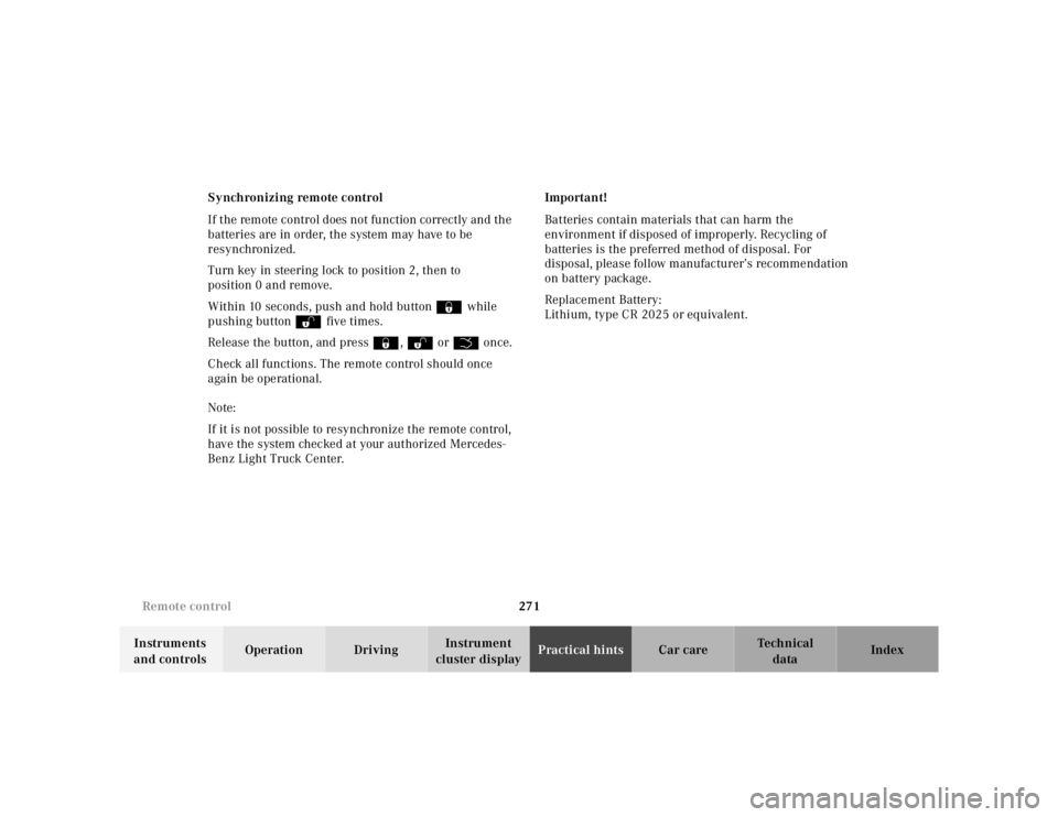
cluster displayPractical hintsCar care Index Synchronizing remote control
If the remote control does not function correctly and the
batteries are in order, the system may have to be
resynchronized.
Turn key in steering lock to position 2, then to
position 0 and remove.
Within 10 seconds, push and hold button‹ while
pushing buttonΠfive times.
Release the button, and press‹, Œ orŠ once.
Check all functions. The remote control should once
again be operational.
Note:
If it is not possible to resynchronize the remote control,
have the system checked at your authorized Mercedes-
Benz Light Truck Center.Important!
Batteries contain materials that can harm the
environment if disposed of improperly. Recycling of
batteries is the preferred method of disposal. For
disposal, please follow manufacturer’s recommendation
on battery package.
Replacement Battery:
Lithium, type CR 2025 or equivalent.
Page 358 of 4133
308 Index
Te ch n ica l
data Instruments
and controlsOperation DrivingInstrument
cluster displayPractical hints Car careIndex
Remote control ................................................................. 24
Battery replacement .................................................270
Changing batteries ...................................................270
Operation ..................................................................... 26
Synchronizing remote control ................................ 271
Removable cargo floor plates ....................................... 129
Replacement keys ............................................................ 25
Replacing bulbs ..............................................................260
Replacing wiper blade insert .......................................275
Reporting safety defects ................................................. 16
Reserve key ................................................................ 24, 25
Roadside assistance ......................................................... 10
Roadside assistance call
See Tele Aid ............................................................... 148
Roof rack ......................................................................... 276
SSafety guidelines for the seat belt, emergency
tensioning retractor and airbag ................................ 63
Screwdriver .....................................................................237
Seat belt warning lamp .................................................223
Seat belts ........................................................................... 46
Fastening ...................................................................... 48
Seat belt nonusage warning system ........................ 47Unfastening .................................................................. 50
Warning lamp ........................................................... 223
Seat belts and integrated restraint system .................. 46
Seat bench ....................................................................... 120
Seats, folding (Third row seats) ................................... 126
Seats, front ........................................................................37
Heated seats .................................................................44
Manual seats ................................................................39
Power seats .................................................................. 40
Service indicator
See Flexible service system (FSS) ............................ 87
Side marker lamp .......................................................... 264
Skyview Top ....................................................................109
Emergency operation .............................................. 273
Sliding/pop-up roof ........................................................107
Emergency operation .............................................. 272
Express opening ........................................................108
Synchronizing .......................................................... 272
Snow chains ....................................................................179
SOS-call
See Tele Aid ...............................................................148
Space-saver tire
Air pump ................................................................... 239
Spare parts service ....................................................... 284
Spare wheel ................................................................... 242
Space-saver tire ........................................................ 243
Page 368 of 4133
DISABLING SYSTEM
Before proceeding, see AIR BAG SAFETY PRECAUTIONS . Record radio presets and obtain anti-theft
code. Turn ignition switch to OFF position and remove ignition key. If welding on vehicle, disconnect negative
battery cable and disconnect air bag control module.
ACTIVATING SYSTEM
Ensure ignition is off. Reconnect air bag system co mponents (if disconnected). Reconnect negative battery
cable. Perform See SYSTEM OPERATION CHECK
.
DISPOSAL PROCEDURES
Several situations may arise requiring so me form of disposal action, including:
Scrapping a vehicle containing a deployed air bag module and-or ETR.
Scrapping a vehicle with a live air bag module and-or ETR.
Disposal of a live but electrically faulty air bag module and-or ETR.
Disposal of a deployed air bag module and-or ETR.
DEPLOYED AIR BAG OR ETR
Deployed air bag module and-or ETR unit can be thrown away. None of its components are reusable. Deployed
air bag module is NOT classified as hazardous material.
SCRAPPED VEHICLE
1. Before proceeding, follow service precautions. See AIR BAG SAFETY PRECAUTIONS . Move
vehicle outdoors to a remote area, away from work shop and other personnel. Disconnect and shield
negative battery cable. Open al l vehicle windows and doors.
2. Ensure air bag module is secured to steering wheel, and passenger air bag is secured to dash. Ensure ETR
seat belt assemblies are secured to "B" pillars and all seat belt buckles are latched. Remove loose ob
jects
CAUTION: On CL500, open doors before
disconnecting battery. Opening doors
allows windows to automa tically lower thus preventing roof seal damage.
WARNING: An undeployed air bag module or ET R should never be disposed of
without first being deplo yed. See SCRAPPED VEHICLE
. If deployment is
not possible, contact vehicle manuf acturer for further instructions.
WARNING: An undeployed air bag m odule and-or ETR seat belt CANNOT be disposed
of without first being de ployed. If this is not possible through procedures
outlined below, contact vehicle ma nufacturer for further instructions.
Perform remote deployment outdoors . Keep personnel at least 20 feet
away.
2001 Mercedes-Benz ML320
2000-01 ACCESSORIES/SAFETY EQUIPMENT Merc edes-Benz - Air Bag Restraint Systems
me
Saturday, October 02, 2010 3:44:45 PMPage 4 © 2006 Mitchell Repair Information Company, LLC.
Page 379 of 4133

module.
2. To install air bag module, reverse removal procedur e. Activate air bag system. Perform system operation
check to ensure system is functioning properly. See SYSTEM OPERATION CHECK
.
Removal & Installation (SLK 320)
1. Before proceeding, See AIR BAG SAFETY PRECAUTIONS . Disable air bag system. See
DISABLING & ACTIVATI NG AIR BAG SYSTEM
. Remove ignition key. Remove top section of
instrument panel. Fold vapor barrier toward front to reveal 2 screws. Disconnect passenger-side air bag
module connector. Remove 4 screws and passenger-side air bag module.
2. To install air bag module, reverse removal procedur e. Activate air bag system. Perform system operation
check to ensure system is functioning properly. See SYSTEM OPERATION CHECK
.
DIAGNOSTICS
Before proceeding, see AIR BAG SAFETY PRECAUTIONS
. The SRS control module is capable of
diagnosing air bag system components and ETR components. If a fault is detected by the SRS control module
or system is malfunctioning, SRS warning light will do one or more of the following:
SRS warning light goes out after 2 minutes. System fault is noted, however occupant protection is not
affected. See RETRIEVING FAULT CODES
.
SRS warning light illuminates cont inuously. System is faulty which may result in a non deployment or
false deployment. See RETRIEVING FAULT CODES
.
SRS warning light blinks continuous ly. Control module has been replaced without setting control module
parameters.
RETRIEVING FAULT CODES
1. Check vehicle fuses. Replace any blown fuses as nece ssary. Ensure vehicle battery voltage is 11 volts or
more. Ensure SRS warning light functions. Turn i gnition off. Connect Hand-Held Tester (HHT) (965 589
00 01) to Data Link Connector (DLC).
2. DLC is located in right rear corner of engine comp artment. It may be necessary to use Adapter (965 589
00 40 or 965 589 00 50) to connect HHT to DLC. Afte r HHT displays module number and version, press
return key to start diagnosis. Us ing HHT, follow HHT prompts to re trieve SRS fault codes. For SRS
control modules beginning with number 000, fault c ode 1 is valid. For SRS control modules beginning
with number 001, fault code 2 is valid. See Fig. 6
.
3. HHT will display a 3 digit fault code, and may display additional graphic information. This additional
graphic information will help in diagnosis of fault code. See Fig. 5
. During diagnosis HHT will display 4
different graphic displays info rming technician if a test passes or fail s, or if seat belt buckle is latched or
NOTE: After component replacement, perf
orm a system operation check to ensure
proper system operation. S ee SYSTEM OPERATION CHECK
.
NOTE: Fault codes may only be retrieved us ing Hand-Held Tester (965 589 00 01) and
Adapter (965 589 00 40 or 965 589 00 50).
2001 Mercedes-Benz ML320
2000-01 ACCESSORIES/SAFETY EQUIPMENT Merc edes-Benz - Air Bag Restraint Systems
me
Saturday, October 02, 2010 3:44:45 PMPage 15 © 2006 Mitchell Repair Information Company, LLC.
Page 502 of 4133
35
Antitheft alarm system
Te ch n ica l
data
Instruments
and controls Operation
Driving Instrument
cluster display Practical hints Car care Index
Antitheft alarm system
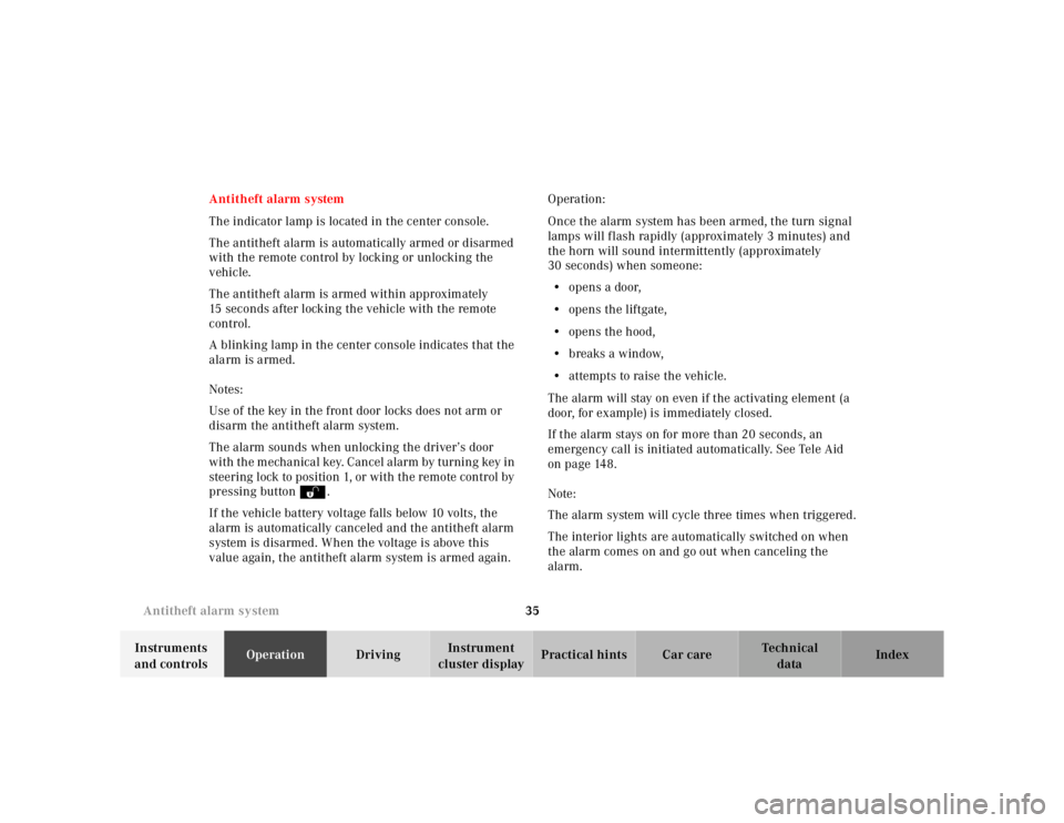
The indicator lamp is located in the center console.
The antitheft alarm is automatically armed or disarmed
with the remote control by locking or unlocking the
vehicle.
The antitheft alarm is armed within approximately
15 seconds after locking the vehicle with the remote
control.
A blinking lamp in the center console indicates that the
alarm is armed.
Notes:
Use of the key in the front door locks does not arm or
disarm the antitheft alarm system.
The alarm sounds when unlocking the driver’s door
with the mechanical key. Cancel alarm by turning key in
steering lock to position 1, or with the remote control by
pressing button Œ.
If the vehicle battery voltage falls below 10 volts, the
alarm is automatically canceled and the antitheft alarm
system is disarmed. When the voltage is above this
value again, the antitheft alarm system is armed again. Operation:
Once the alarm system has been armed, the turn signal
lamps will flash rapidly (approximately 3 minutes) and
the horn will sound intermittently (approximately
30 seconds) when someone:
• opens a door,
• opens the liftgate,
• opens the hood,
• breaks a window,
• attempts to raise the vehicle.
The alarm will stay on even if the activating element (a
door, for example) is immediately closed.
If the alarm stays on for more than 20 seconds, an
emergency call is initiated automatically. See Tele Aid
on page 148.
Note:
The alarm system will cycle three times when triggered.
The interior lights are automatically switched on when
the alarm comes on and go out when canceling the
alarm.
Page 555 of 4133

88
Flexible service system
Te ch n ica l
data
Instruments
and controls Operation
Driving Instrument
cluster display Practical hints Car care Index
Important!
The FSS indicator is not an engine oil level indicator.
See page 89 for engine oil level indicator.
Notes:
When disconnecting vehicle battery for one or more
days at a time, such days will not be counted. Any such
days not counted by the FSS can be added by your
Mercedes-Benz Light Truck Center.
The interval between services is determined by the type
of driving for which the vehicle is used. For example,
driving at extreme speeds, and cold starts combined
with short distance driving in which the engine does not
reach normal operating temperature, reduce the interval
between services.
Following a completed A or B service the Mercedes-
Benz Light Truck Center sets the counter mileage to
10 000 miles (Canada: 15 000 km) and 365 days.
The counter can also be set by any individual. To do so: 1. Turn the key in steering lock to position 2.
2. Immediately press button (1) twice within one second. 3. The present status for days or distance is displayed.
Within 10 seconds turn key in steering lock to
position 0.
4. Press and hold button (1), while turning key in steering lock to position 2 again. The present status
for days or distance is displayed once more.
Continue to hold button (1).
After approximately 10 seconds a signal sounds, and
the display shows 10 000 miles (Canada: 15 000 km)
for approximately 10 seconds.
5. Release button (1).
If the FSS counter was inadvertently reset, have it
corrected at a Mercedes-Benz Light Truck Center.
Notes:
The FSS allows for distances between 10 000 miles
(Canada: 15 000 km) and 20 000 miles (Canada:
30 000 km), or from 365 to 730 days between services.
However you choose to set your reference numbers, the
scheduled services as posted in the Service Booklet
must be followed to properly care for your vehicle.
Page 615 of 4133
148
Tele Aid
Te ch n ica l
data
Instruments
and controls Operation
Driving Instrument
cluster display Practical hints Car care Index
Tele Aid
Important!
The initial activation of the Tele Aid system may only be
performed by completing the subscriber agreement and
placing an acquaintance call using the “SOS” button.
Failure to complete either of these steps will result in a
system that is not activated. If the system is not
activated the indicator lamp in the “SOS” button stays
on after turning electronic key in starter switch to
position 2 and the message “TELE AID – NOT
ACTIVATED” will be shown in the MCS display for
approx. 10 seconds.
If you have any questions regarding activation, please
call the Response Center at 1-800-756-9018 (in the USA)
or 1-888-923-8367 (in Canada).
( Tele matic Alarm Identification on Demand)
The Tele Aid system consists of three types of response;
automatic and manual emergency, roadside assistance
and information. The Tele Aid system is operational providing that the
vehicle’s battery is charged, properly connected, not
damaged and cellular and GPS coverage is available.
The speaker volume of a Tele Aid call can be adjusted
using the volume control on the MCS unit. To activate,
press the “SOS” button, the Roadside Assistance
button • or the Information button ¡, depending
on the type of response required.
Shortly after the completion of your Acquaintance Call,
you will receive a user ID and password via first call
mail. By visiting www.mbusa.com and selecting
“Tele Aid” (USA only), you will have access to account
information, remote door unlock, Info Services
* profile
and more.
* OptionalSystem self-check
Initially, after turning the key in steering lock to
position 2, malfunctions are detected and indicated (the
indicator lamps in the “SOS” button, the Roadside
Assistance button • and Information button ¡
stay on longer than 10 seconds or do not come on). The
message “TELE AID – PLEASE VISIT WORKSHOP”
appears in the MCS display.
Page 630 of 4133
163
Steering lock
Te ch n ica l
data
Instruments
and controls Operation
Driving Instrument
cluster display Practical hints Car care Index
Caution!
To prevent accelerated battery discharge and a possible
dead battery, always remove the key from the steering
lock. Do not leave the key in steering lock position 0.
Notes:
A warning sounds when the driver’s door is opened
while the key is in steering lock position 1 or 0.
With the engine at idle speed, the charging rate of the
alternator (output) is limited. It is therefore recommended that you turn off
unnecessary electrical consumers while driving in stop-
and-go traffic. This precaution helps to avoid draining of
the battery.
Unnecessary strain on the battery and charging system
may be minimized by turning off the following power
consumers, for example: Heated seats, rear window
defroster.