1997 MERCEDES-BENZ ML350 key battery
[x] Cancel search: key batteryPage 1132 of 4133

328 IndexK
Key
Global locking 89
Global unlocking 89
Loss of 90
Positions in steering lock 33
Remote control with folding key 88
Unlocking liftgate 89
Unlocking the driver’s door, fuel filler
flap 89
Key positions in steering lock 33
Key, Mechanical 261
Key, Remote control
Unlocking with 32
Kickdown 123, 313
L
Labels, identification 292
Lamp bulbs, exterior 266
Lamps, exterior
Front 266
Rear 267Lamps, indicator and warning
4-ETS 251, 252
ABS 242
Adjustable steering column 253
AIRBAG OFF 63, 243
BAS 78, 245, 246, 247
Battery indicator lamp 254
Brake pad wear 254
Brakes 244
CHECK ENGINE 248
Coolant 249
EBP 245
Engine diagnostics 248
ESP 245, 246, 247, 251
Front fog lamps 253
Fuel reserve 252
Low engine oil level 253
LOW RANGE 252
Low washer system fluid level 253
Seat belts 253
Service indicator 232
SRS 255
Turn signals 25LATCH child seat anchors 72
LATCH child seat mounts 72
Layout of poly-V-belt drive 293
Leather upholstery
Cleaning 239
Lever
For cruise control 150
License plate lamps
Replacing bulbs 267, 271
Liftgate
Closing 92
Opening 89, 91
Opening from inside 91
Opening from outside 91
Light alloy wheels
Cleaning 238
Lighter
Rear center console 169
Lighter see cigarette lighter 168
Page 1137 of 4133

333 Index
Reading lamps 114
Rear automatic climate control 141
Adjusting air volume and air distribu-
tion manually 141
Automatic mode 141
Rear bench seat
Foldable 99
Rear door window
Blocking operation 73
Rear fog lamp 267
Bulb 267
Switching on 111
Rear lamp bulbs
Replacing 270
Rear parking lamp
Replacing bulbs 270
Rear passenger compartment ventilation
and climate control
Activating 141
Deactivating 141
Rear passenger compartment ventilation
and rear automatic climate
control 141Rear quarter windows* 146
Opening 146
Closing 147
Rear seats 99
Easy entry/exit feature* 101
Enlarging cargo area 99
Folding down backrest 100
Folding up 101
Folding up backrest 100
Fore and aft 99
Lowering 100
Third row* 102
Rear standing lamp
Replacing bulbs 270
Rear towing eyes 285
Rear view mirror automatic antiglare 126
Rear view mirrors see Mirrors
Rear window defroster 133
Activating 133
Deactivating 133Rear window wiper 131
Rain sensor* 131
Rear window wiper/washer 51
Reconnecting
Vehicle battery 279
Refrigerant
Air conditioning 302
Refueling 214
Regular checks 215
Reinstalling vehicle battery 279
Remote control
Changing battery 262
Global locking 89
Global unlocking 89
Synchronizing 263
Unlocking liftgate 89
Unlocking the driver’s door, fuel filler
flap 89
Unlocking with 32
Remote control with folding key 88
Page 1489 of 4133

AR54.10-P-0005GH
Remove/install battery
23.3.00
MODEL
163.113 /128 /136 /154 /157 /172 /174 /175
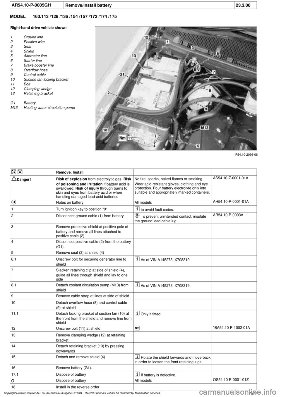
P54.10-2066-06
Right-hand drive vehicle shown
1
Ground line
2
Positive wire
3
Seal
4
Shield
5
Alternator line
6
Starter line
7
Brake booster line
8
Overflow hose
9
Control cable
10
Suction fan locking bracket
11
Bolt
12
Clamping wedge
13
Retaining bracket
G1 Battery
M13
Heating water circulation pump
Remove, Install
Danger!
Risk of explosion
from electrolytic gas.
Risk
of poisoning and irritation
if battery acid is
swallowed.
Risk of injury
through burns to
skin and eyes from battery acid or when
handling damaged lead-acid batteries
No fire, sparks, naked flames or smoking.
Wear acid-resistant gloves, clothing and eye
protection. Pour battery electrolyte only into
suitable and appropriately marked containers.
AS54.10-Z-0001-01A
Notes on battery
All models
AH54.10-P-0001-01A
1
Turn ignition key to position "0"
to avoid fault codes.
2
Disconnect ground cable (1) from battery
To prevent unintended contact, insulate
the ground lead cable lug.
AR54.10-P-0003A
3
Remove protective shield at positive pole of
battery and remove all lines attached to
positive cable (2)
4
Disconnect positive cable (2) from the battery
(G1).
5
Remove seal (3) at shield (4)
6.1
Unscrew bolt for securing generator line to
shield
As of VIN A145273, X708319.
7
Slacken retaining clip at side of shield (4),
guide all lines through shield and lay to one
side
8.1
Detach coolant circulation pump (M13) from
shield
As of VIN A145273, X708319.
9
Remove cable strap at lines at side of shield
10
Detach overflow hose (8) and control cable
(9) at shield
11.1
Detach locking bracket of suction fan (10) at
the front from the shield and remove line from
shield
Only if fitted.
12
Unscrew bolt (11) at shield
*BA54.10-P-1002-01A
13
Remove clamping wedge (12) at retaining
bracket
14
Detach retaining bracket (13) by pressing
downwards
15
Detach and remove shield (4)
Rotate the shield forwards and move back
in order to loosen the front retaining lugs.
16
Remove battery (G1).
17.1
Dispose of battery
If battery is defective.
o
Dispose of battery
All models
OS54.10-P-0001-01Z
18
Install in the reverse order
Copyright DaimlerChrysler AG 05.06.2006 CD-Ausgabe G/10/04 . This WIS print-out will not be recorde
d by Modification services.
Page 1
Page 1684 of 4133

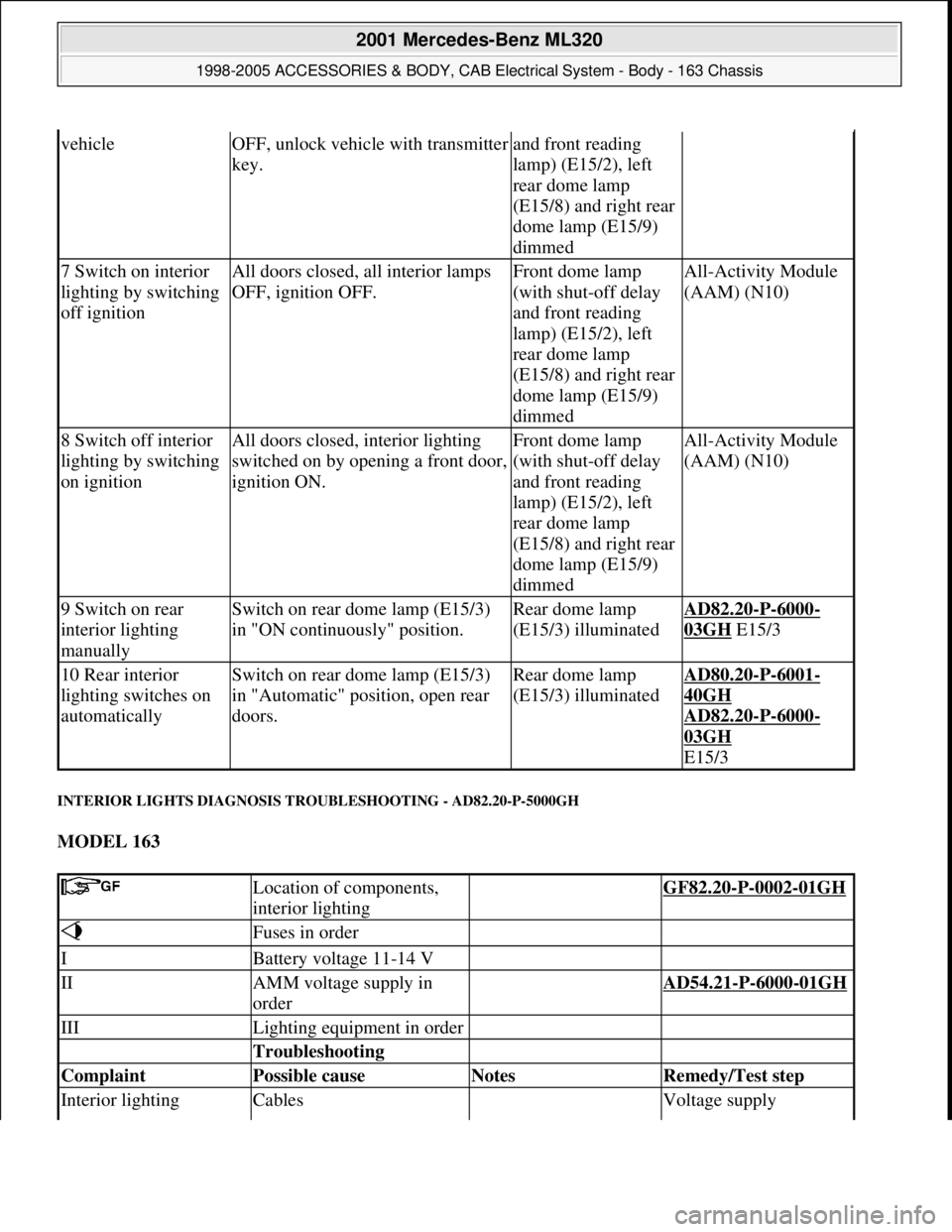
INTERIOR LIGHTS DIAGNOSIS TROUBLESHOOTING - AD82.20-P-5000GH
MODEL 163
vehicleOFF, unlock vehicle with transmitter
key.and front reading
lamp) (E15/2), left
rear dome lamp
(E15/8) and right rear
dome lamp (E15/9)
dimmed
7 Switch on interior
lighting by switching
off ignitionAll doors closed, all interior lamps
OFF, ignition OFF.Front dome lamp
(with shut-off delay
and front reading
lamp) (E15/2), left
rear dome lamp
(E15/8) and right rear
dome lamp (E15/9)
dimmedAll-Activity Module
(AAM) (N10)
8 Switch off interior
lighting by switching
on ignitionAll doors closed, interior lighting
switched on by opening a front door,
ignition ON.Front dome lamp
(with shut-off delay
and front reading
lamp) (E15/2), left
rear dome lamp
(E15/8) and right rear
dome lamp (E15/9)
dimmedAll-Activity Module
(AAM) (N10)
9 Switch on rear
interior lighting
manuallySwitch on rear dome lamp (E15/3)
in "ON continuously" position.Rear dome lamp
(E15/3) illuminatedAD82.20-P-6000-
03GH E15/3
10 Rear interior
lighting switches on
automaticallySwitch on rear dome lamp (E15/3)
in "Automatic" position, open rear
doors.Rear dome lamp
(E15/3) illuminatedAD80.20-P-6001-
40GH
AD82.20
-P-6000-
03GH
E15/3
Location of components,
interior lighting GF82.20-P-0002-01GH
Fuses in order
IBattery voltage 11-14 V
IIAMM voltage supply in
order AD54.21-P-6000-01GH
IIILighting equipment in order
Troubleshooting
Complaint Possible cause Notes Remedy/Test step
Interior lighting Cables Voltage supply
2001 Mercedes-Benz ML320
1998-2005 ACCESSORIES & BODY, CAB Electrical System - Body - 163 Chassis
me
Saturday, October 02, 2010 3:30:07 PMPage 189 © 2006 Mitchell Repair Information Company, LLC.
Page 1688 of 4133

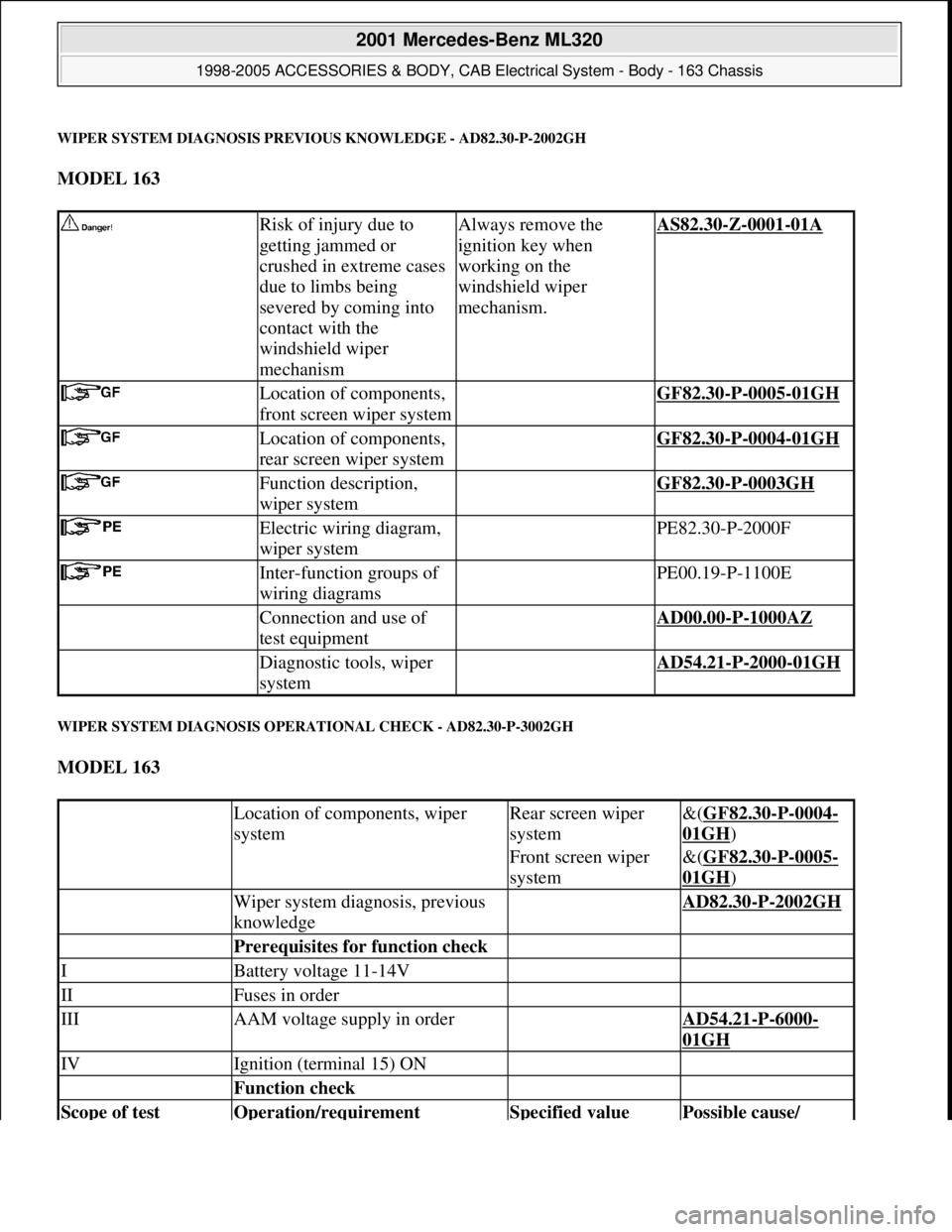
WIPER SYSTEM DIAGNOSIS PREVIOUS KNOWLEDGE - AD82.30-P-2002GH
MODEL 163
WIPER SYSTEM DIAGNOSIS OPERATIONAL CHECK - AD82.30-P-3002GH
MODEL 163
Risk of injury due to
getting jammed or
crushed in extreme cases
due to limbs being
severed by coming into
contact with the
windshield wiper
mechanismAlways remove the
ignition key when
working on the
windshield wiper
mechanism.AS82.30-Z-0001-01A
Location of components,
front screen wiper system GF82.30-P-0005-01GH
Location of components,
rear screen wiper system GF82.30-P-0004-01GH
Function description,
wiper system GF82.30-P-0003GH
Electric wiring diagram,
wiper system PE82.30-P-2000F
Inter-function groups of
wiring diagrams PE00.19-P-1100E
Connection and use of
test equipment AD00.00-P-1000AZ
Diagnostic tools, wiper
system AD54.21-P-2000-01GH
Location of components, wiper
systemRear screen wiper
system&(GF82.30-P-0004-
01GH)
Front screen wiper
system&(GF82.30-P-0005-
01GH)
Wiper system diagnosis, previous
knowledge AD82.30-P-2002GH
Prerequisites for function check
IBattery voltage 11-14V
IIFuses in order
IIIAAM voltage supply in order AD54.21-P-6000-
01GH
IVIgnition (terminal 15) ON
Function check
Scope of test Operation/requirement Specified value Possible cause/
2001 Mercedes-Benz ML320
1998-2005 ACCESSORIES & BODY, CAB Electrical System - Body - 163 Chassis
me
Saturday, October 02, 2010 3:30:07 PMPage 193 © 2006 Mitchell Repair Information Company, LLC.
Page 1695 of 4133

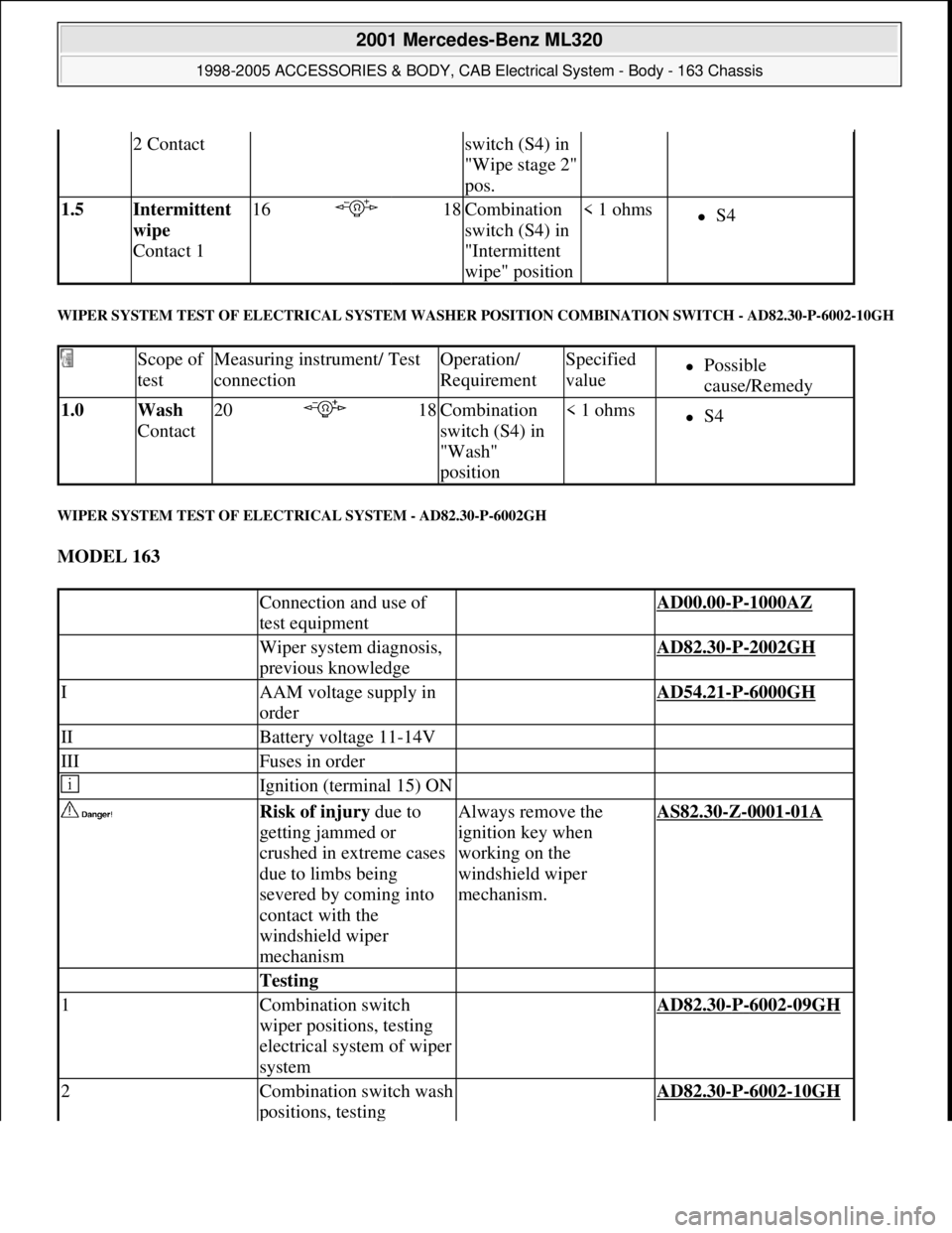
WIPER SYSTEM TEST OF ELECTRICAL SYSTEM WASHER POSITION COMBINATION SWITCH - AD82.30-P-6002-10GH
WIPER SYSTEM TEST OF ELECTRICAL SYSTEM - AD82.30-P-6002GH
MODEL 163
2 Contactswitch (S4) in
"Wipe stage 2"
pos.
1.5 Intermittent
wipe
Contact 116 18Combination
switch (S4) in
"Intermittent
wipe" position< 1 ohmsS4
Scope of
testMeasuring instrument/ Test
connectionOperation/
RequirementSpecified
valuePossible
cause/Remedy
1.0 Wash
Contact20 18Combination
switch (S4) in
"Wash"
position< 1 ohmsS4
Connection and use of
test equipment AD00.00-P-1000AZ
Wiper system diagnosis,
previous knowledge AD82.30-P-2002GH
IAAM voltage supply in
order AD54.21-P-6000GH
IIBattery voltage 11-14V
IIIFuses in order
Ignition (terminal 15) ON
Risk of injury due to
getting jammed or
crushed in extreme cases
due to limbs being
severed by coming into
contact with the
windshield wiper
mechanismAlways remove the
ignition key when
working on the
windshield wiper
mechanism.AS82.30-Z-0001-01A
Testing
1Combination switch
wiper positions, testing
electrical system of wiper
system AD82.30-P-6002-09GH
2Combination switch wash
positions, testing AD82.30-P-6002-10GH
2001 Mercedes-Benz ML320
1998-2005 ACCESSORIES & BODY, CAB Electrical System - Body - 163 Chassis
me
Saturday, October 02, 2010 3:30:07 PMPage 200 © 2006 Mitchell Repair Information Company, LLC.
Page 2139 of 4133

GF54.21-P-4106-01GH
Extended Activity Module - Task
n
The primary tasks of the Extended Activity Module (EAM, N10/1) are
as follows:
D
To control the door sill lights
D
To suppress the auto-dimming mirror function
D
To control the headlight cleaning system (HCS)
D
To control the rear window defroster
D
To control seat heating
D
To control the power supply via control console to tilt/sliding or
louvered sunroof switch
D
To control the PTC heater booster (R22/3)
D
To control the auxiliary fan (M4)
D
To read the cruise control switch (S40) and relay data to control
module (DAS, N73/1)
D
To read the contacts for wiper speed settings 1 and 2 on
combination switch (S4) for diagnosis.
To perform these tasks the Extended Activity Module (EAM, N10/1)
reads various signals and switch settings directly.
The Extended Activity Module (EAM, N10/1) interfaces with other
control modules via the engine compartment CAN.
-----------------------------------------------------------------------------------------
Diagnosis
Diagnosis is performed using the Star diagnostic tool. To facilitate
this task, the Extended Activity Module (EAM, N10/1) is equipped
with its own diagnostics cable.
This cable is also used to diagnose the
All Activity Module (AAM,
N10)
and the
transfer case control module (N78)
.
The Extended Activity Module (EAM, N10/1) is linked to the All
Activity Module (AAM, N10) via the
engine compartment CAN
.
Data communication between the All Activity Module (AAM,
N10) and the Extended Activity Module (EAM, N10/1) is
assumed by the
CAN (N10 - N10/1)
when terminal 15 is off.
The CAN (N10 - N10/1)
is an independent CAN bus located
between the All Activity Module (AAM, N10) and the Extended
Activity Module (EAM, N10/1).
No other
control modules are
connected to the CAN (N10 - N10/1).
-----------------------------------------------------------------------------------------
Details:
Door sill lights
When the front interior light is on and one of the front doors is open,
or when the rear interior light is on and one of the back doors is open,
the door sill lights for the open door will illuminate.
Headlight cleaning system (HCS)
Activating a separate switch causes the EAM to send a turn-on signal
to the HCS pump relay.
EAM will send an additional turn-on signal to the HCS pump relay
only after the cleaning operation is completed and a "rest period" of
approximately 2.5 sec. has passed.
Auto-dimming mirror function
The auto-dimming mirror function is suppressed when the interior
light is on or reverse gear is engaged.
Auto-dimming suppression for the outside rearview mirror (slave) is
activated by the inside rearview mirror (master).
Heater booster/PTC air heater for diesel engines
EAM monitors system voltage and adjusts heater booster capacity to
minimize load on battery.
Rear window defroster
EAM sets maximum ON time for rear window defroster depending
on outdoor temperature and current vehicle speed.
D
Standard ON time:
10 min.
D
Outdoor temperature < 5
o
C:
Additional 5 min.
D
Speed >80 km/h:
Additional 3 min.
Seat heating
Sets maximum seat heating time.
D
Setting 1: max. 20 min.
D
Setting 2: max. 5 min.
Tilt/sliding or louvered sunroofs
Signal via AAM2 allows operation of tilt/sliding or louvered sunroofs
when ignition is on (standard mode) or off (keyless mode).
Ignition authorization via CAN
The EAM issues ignition authorization to AAM2 via the engine
compartment CAN depending on the requirements of the engine
control unit in connection with the FBM.
Copyright DaimlerChrysler AG 18.05.2006 CD-Ausgabe G/10/04 . This WIS print-out will not be recorde
d by Modification services.
Page 1
Page 2883 of 4133
![MERCEDES-BENZ ML350 1997 Complete Repair Manual MODELS 124, 129, 140, 163 up to 30.11.99, 163 as of 1.9.01, 168, 170, 201, 202, 208, 210, 215, 220
EXPLANATION OF SYMBOLS FOR TESTERS AND COMPONENTS - AD00.00-P-2000-01A
0.0 [] 1Key to diagnostics
s MERCEDES-BENZ ML350 1997 Complete Repair Manual MODELS 124, 129, 140, 163 up to 30.11.99, 163 as of 1.9.01, 168, 170, 201, 202, 208, 210, 215, 220
EXPLANATION OF SYMBOLS FOR TESTERS AND COMPONENTS - AD00.00-P-2000-01A
0.0 [] 1Key to diagnostics
s](/manual-img/4/57306/w960_57306-2882.png)
MODELS 124, 129, 140, 163 up to 30.11.99, 163 as of 1.9.01, 168, 170, 201, 202, 208, 210, 215, 220
EXPLANATION OF SYMBOLS FOR TESTERS AND COMPONENTS - AD00.00-P-2000-01A
0.0 [] 1Key to diagnostics
symbols AD00.00-P-2001A
0.0 [] 2Diagnosis assignmentexcept models 215, 220AD00.00-P-2002A
0.0 [] 3Connect test equipment
diagnosisexcept model 215AD00.00-P-2003A
0.0 [] 4Diagnostic procedureonly for vehicle systems
that can be diagnosed using
STAR DIAGNOSISAD00.00-P-2004A
DescriptionLogoDescriptionLogoDescriptionLogo
ABS Adapter Battery Short-circuit
35-pin socket
box Direct current
generator Short-circuit to
ground
126-pin socket
box Direct current
motor Open-circuit
Function
generator Capacitor Multimeter
alternating
voltage type of
measurement
Hand-Held
Tester Coil Multimeter
resistance type of
measurement
Pulse counter Resistance Function
generator square-
wave signal shape
Lambda control
tester Ground Function
generator
sinusoidal signal
shape
Pressure gauge In order Oscilloscope
Multimeter Fault Adapter cable
with light-
emitting diode
Decade resistor Greater than > Multimeter direct
current type of
measurement
Bridge Less than < Multimeter
alternating
current type of
measurement
2004 Mercedes-Benz ML350
1998-2005 GENINFO Overall vehicle - 163 Chassis
me
Saturday, October 02, 2010 3:47:48 PMPage 238 © 2006 Mitchell Repair Information Company, LLC.