1997 MERCEDES-BENZ ML350 steering angle sensor
[x] Cancel search: steering angle sensorPage 1184 of 4133
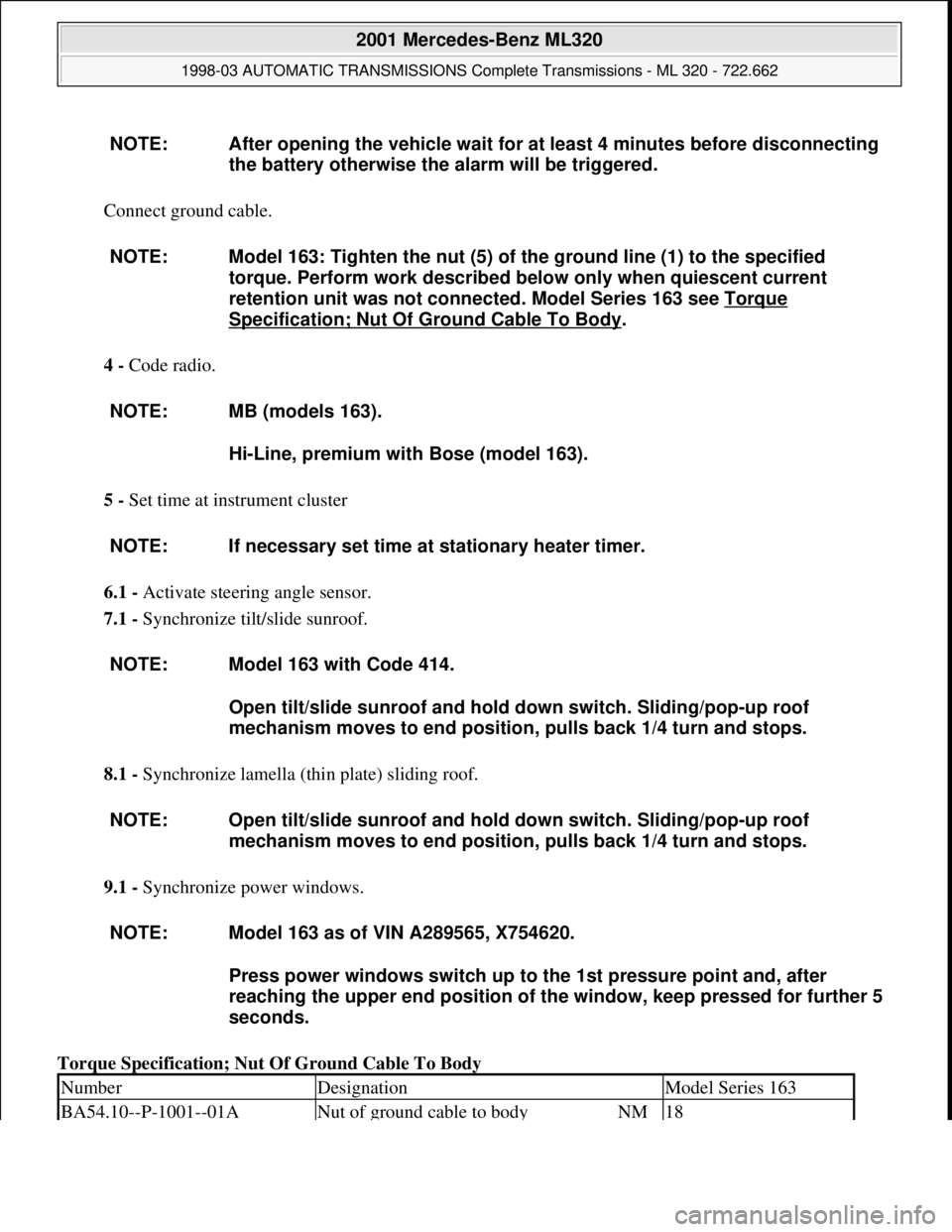
Connect ground cable.
4 - Code radio.
5 - Set time at instrument cluster
6.1 - Activate steering angle sensor.
7.1 - Synchronize tilt/slide sunroof.
8.1 - Synchronize lamella (thin plate) sliding roof.
9.1 - Synchronize power windows.
Torque Specification; Nut Of Ground Cable To Body NOTE: After opening the vehicle wait for at least 4 minutes before disconnecting
the battery otherwise the alarm will be triggered.
NOTE: Model 163: Tighten the nut (5) of the ground line (1) to the specified
torque. Perform work described below only when quiescent current
retention unit was not connected. Model Series 163 see Torque
Specification; Nut Of Ground Cable To Body.
NOTE: MB (models 163).
Hi-Line, premium with Bose (model 163).
NOTE: If necessary set time at stationary heater timer.
NOTE: Model 163 with Code 414.
Open tilt/slide sunroof and hold down switch. Sliding/pop-up roof
mechanism moves to end position, pulls back 1/4 turn and stops.
NOTE: Open tilt/slide sunroof and hold down switch. Sliding/pop-up roof
mechanism moves to end position, pulls back 1/4 turn and stops.
NOTE: Model 163 as of VIN A289565, X754620.
Press power windows switch up to the 1st pressure point and, after
reaching the upper end position of the window, keep pressed for further 5
seconds.
NumberDesignationModel Series 163
BA54.10--P-1001--01ANut of ground cable to bodyNM18
2001 Mercedes-Benz ML320
1998-03 AUTOMATIC TRANSMISSIONS Complete Transmissions - ML 320 - 722.662
me
Saturday, October 02, 2010 3:15:25 PMPage 15 © 2006 Mitchell Repair Information Company, LLC.
Page 2042 of 4133

3. Normalize side power windows. See NORMALIZING POWER WINDOWS .
4. Start engine and run at idle. Turn steering wheel from one lock position to the other to activate steering
angle sensor. Center steering wheel. Message "EI. STAB. PROGRAM GO TO GARAGE" should erase
from multifunction display panel.
5. If equipped, normalize tilting/sliding roof. See NORMALIZING TILTING/SLIDING ROOF
.
6. If equipped, normalize memory power seats, steering column and outside mirror if components are
installed. See NORMALIZING MEMORY POWER SEATS, STEERING COLUMN & OUTSIDE
MIRROR .
Normalizing Power Windows
1. Completely close each window with manual switch. Hold switch in closed position for .3 second.
2. Repeat procedure for each power window.
Normalizing Memory Power Seats, Steering Column & Outside Mirror
1. Using manual switch, move seat to each end position and hold for .3 second. Repeat procedure for each
switch except rear stop of backrest.
2. Repeat procedure for end positions of steering wheel and outside mirrors.
Normalizing Tilting/Sliding Roof
Open roof with SR switch until mechanical stop is reached. Continue to press switch for .5 seconds.
Setting Time
1. Use bottom left button on steering wheel to scroll through menus on instrument cluster to "Settings"
menu.
2. Move selection marker with + or - button to "Time" submenu.
3. Press up or down arrows to "Clock, hours" setting. Confirm selection marker is on the hour setting.
4. Press + or - to set hour. Press reset knob in instrument cluster to confirm.
5. Move selection marker with + or - button to "Time" submenu.
6. Press up or down arrows to "Clock, minutes" setting. Confirm selection marker is on the minutes setting.
7. Press + or - to set minute. Press reset knob in instrument cluster to confirm.
TESTING
If generator malfunctions, check for Diagnostic Trouble Codes (DTCs) in Motor Electronics Sequential Fuel
Injection (ME-SFI) system. See appropriate SELF-DIAGNOSTICS article in ENGINE PERFORMANCE. If
cause of generator malfunction is not engine performance related, replace generator.
RETRIEVING & ERASING DIAGNOSTIC TROUBLE CODES
NOTE: Before replacing any component that scan tool suggests are faulty, ensure that
all wiring connections and harness connectors are okay. Ensure that power and
2001 Mercedes-Benz ML320
2001-04 STARTING & CHARGING SYSTEMS Generators & Regulators - 163 Chassis
me
Saturday, October 02, 2010 3:20:32 PMPage 8 © 2006 Mitchell Repair Information Company, LLC.
Page 2145 of 4133
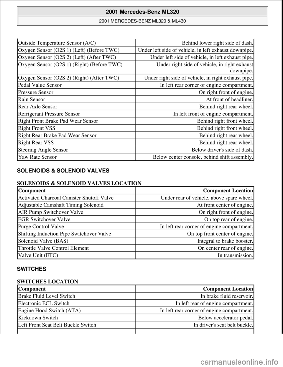
SOLENOIDS & SOLENOID VALVES
SOLENOIDS & SOLENOID VALVES LOCATION
SWITCHES
SWITCHES LOCATION
Outside Temperature Sensor (A/C)Behind lower right side of dash.
Oxygen Sensor (O2S 1) (Left) (Before TWC)Under left side of vehicle, in left exhaust downpipe.
Oxygen Sensor (O2S 2) (Left) (After TWC)Under left side of vehicle, in left exhaust pipe.
Oxygen Sensor (O2S 1) (Right) (Before TWC)Under right side of vehicle, in right exhaust
downpipe.
Oxygen Sensor (O2S 2) (Right) (After TWC)Under right side of vehicle, in right exhaust pipe.
Pedal Value SensorIn left rear corner of engine compartment.
Pressure SensorOn right front of engine.
Rain SensorAt front of headliner.
Rear Axle SensorBehind right rear wheel.
Refrigerant Pressure SensorIn left front of engine compartment.
Right Front Brake Pad Wear SensorBehind right front wheel.
Right Front VSSBehind right front wheel.
Right Rear Brake Pad Wear SensorBehind right rear wheel.
Right Rear VSSBehind right rear wheel.
Steering Angle SensorBelow driver's side of dash.
Yaw Rate SensorBelow center console, behind shift assembly.
ComponentComponent Location
Activated Charcoal Canister Shutoff ValveUnder rear of vehicle, above spare wheel.
Adjustable Camshaft Timing SolenoidAt front center of engine.
AIR Pump Switchover ValveOn right front of engine.
EGR Switchover ValveOn top rear of engine.
Purge Control ValveIn left rear corner of engine compartment.
Shifting Induction Pipe Switchover ValveOn top front center of engine.
Solenoid Valve (BAS)Integral to brake booster.
Throttle Valve Control ElementOn center rear of engine.
Valve Unit (ETC)In transmission.
ComponentComponent Location
Brake Fluid Level SwitchIn brake fluid reservoir.
Electronic ECL SwitchIn left rear of engine compartment.
Engine Hood Switch (ATA)In left rear corner of engine compartment.
Kickdown SwitchBelow accelerator pedal.
Left Front Seat Belt Buckle SwitchIn driver's seat belt buckle.
2001 Mercedes-Benz ML320
2001 MERCEDES-BENZ ML320 & ML430
me
Saturday, October 02, 2010 3:21:17 PMPage 5 © 2006 Mitchell Repair Information Company, LLC.
Page 3039 of 4133
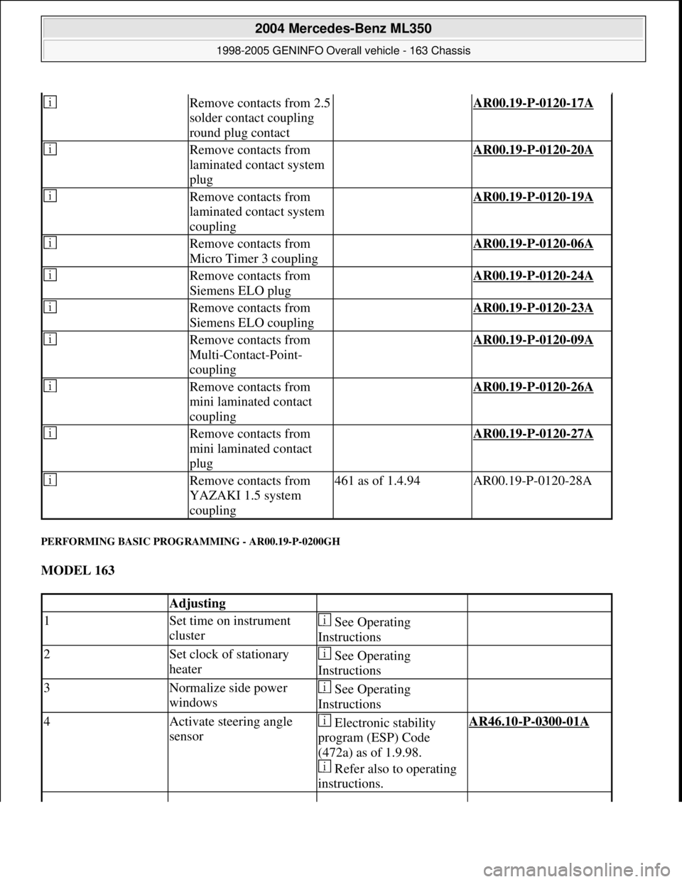
PERFORMING BASIC PROGRAMMING - AR00.19-P-0200GH
MODEL 163
Remove contacts from 2.5
solder contact coupling
round plug contact AR00.19-P-0120-17A
Remove contacts from
laminated contact system
plug AR00.19-P-0120-20A
Remove contacts from
laminated contact system
coupling AR00.19-P-0120-19A
Remove contacts from
Micro Timer 3 coupling AR00.19-P-0120-06A
Remove contacts from
Siemens ELO plug AR00.19-P-0120-24A
Remove contacts from
Siemens ELO coupling AR00.19-P-0120-23A
Remove contacts from
Multi-Contact-Point-
coupling AR00.19-P-0120-09A
Remove contacts from
mini laminated contact
coupling AR00.19-P-0120-26A
Remove contacts from
mini laminated contact
plug AR00.19-P-0120-27A
Remove contacts from
YAZAKI 1.5 system
coupling461 as of 1.4.94AR00.19-P-0120-28A
Adjusting
1Set time on instrument
cluster See Operating
Instructions
2Set clock of stationary
heater See Operating
Instructions
3Normalize side power
windows See Operating
Instructions
4Activate steering angle
sensor Electronic stability
program (ESP) Code
(472a) as of 1.9.98.
Refer also to operating
instructions.AR46.10-P-0300-01A
2004 Mercedes-Benz ML350
1998-2005 GENINFO Overall vehicle - 163 Chassis
me
Saturday, October 02, 2010 3:47:52 PMPage 394 © 2006 Mitchell Repair Information Company, LLC.
Page 3885 of 4133
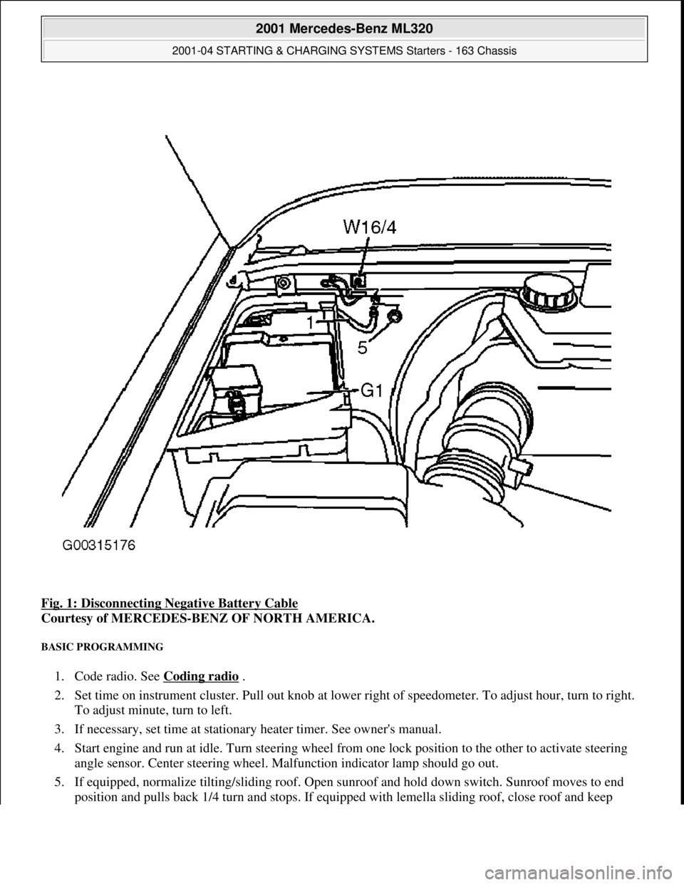
Fig. 1: Disconnecting Negative Battery Cable
Courtesy of MERCEDES-BENZ OF NORTH AMERICA.
BASIC PROGRAMMING
1. Code radio. See Coding radio .
2. Set time on instrument cluster. Pull out knob at lowe r right of speedometer. To adjust hour, turn to right.
To adjust minute, turn to left.
3. If necessary, set time at stationary heater timer. See owner's manual.
4. Start engine and run at idle. Turn steering wheel fr om one lock position to the other to activate steering
angle sensor. Center steering wheel. Ma lfunction indicator lamp should go out.
5. If equipped, normalize ti lting/sliding roof. Open sunroof and hold down switch. Sunroof moves to end
position and pulls back 1/4 turn and stops. If equipped with lemella slidin
g roof, close roof and keep
2001 Mercedes-Benz ML320
2001-04 STARTING & CHARGING SYSTEMS Starters - 163 Chassis
me
Saturday, October 02, 2010 3:19:47 PMPage 3 © 2006 Mitchell Repair Information Company, LLC.