Page 3587 of 4133

Seat belts/belt tensioners
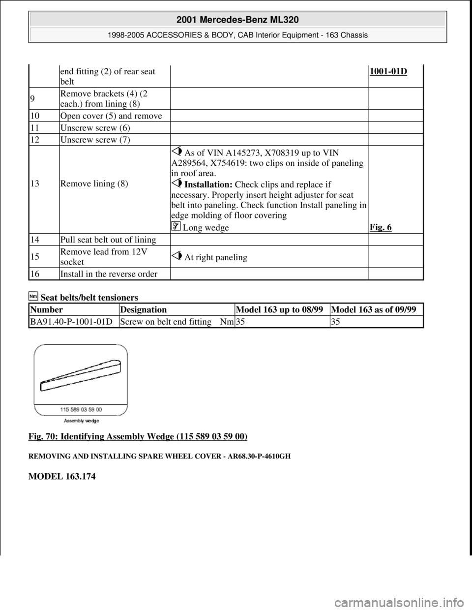
Fig. 70: Identifying Assembly Wedge (115 589 03 59 00)
REMOVING AND INSTALLING SPARE WHEEL COVER - AR68.30-P-4610GH
MODEL 163.174
end fitting (2) of rear seat
belt1001-01D
9Remove brackets (4) (2
each.) from lining (8)
10Open cover (5) and remove
11Unscrew screw (6)
12Unscrew screw (7)
13Remove lining (8)
As of VIN A145273, X708319 up to VIN
A289564, X754619: two clips on inside of paneling
in roof area.
Installation: Check clips and replace if
necessary. Properly insert height adjuster for seat
belt into paneling. Check function Install paneling in
edge molding of floor covering
Long wedgeFig. 6
14Pull seat belt out of lining
15Remove lead from 12V
socket At right paneling
16Install in the reverse order
NumberDesignationModel 163 up to 08/99Model 163 as of 09/99
BA91.40-P-1001-01DScrew on belt end fittingNm3535
2001 Mercedes-Benz ML320
1998-2005 ACCESSORIES & BODY, CAB Interior Equipment - 163 Chassis
me
Saturday, October 02, 2010 3:35:22 PMPage 69 © 2006 Mitchell Repair Information Company, LLC.
Page 3588 of 4133
Fig. 71: Identifying Spare Wheel Cover Components
Wheels
REMOVE/INSTALL PANELING ON B-PILLAR - AR68.30-P-4700GH
Removal, installation
1Remove cargo space cover See Owner's Manual.
2Loosen retaining straps (2) and remove
spare wheel cover front section (1)
3Remove spare wheel *BA40.10-P-
1002-01A
4Remove electric air pump (3)
5Unscrew screws (4) and remove spare
wheel mount (5)
6Remove bracket (6) Turn in clockwise direction until
bracket (6) releases at D-pillar.
7Remove rear wall on spare wheel cover 2 screws.
8Install in opposite order
NumberDesignationModel 163.174
BA40.10-P-1002-01ABolt for spare wheel on inside of spare wheel mountNm50
2001 Mercedes-Benz ML320
1998-2005 ACCESSORIES & BODY, CAB Interior Equipment - 163 Chassis
me
Saturday, October 02, 2010 3:35:22 PMPage 70 © 2006 Mitchell Repair Information Company, LLC.
Page 3604 of 4133

AR68.20-P-4810GH
Removing and installing luggage compartment floor covering
28.2.97
MODEL
163.113 /128 /136 /154 /157 /172 /174 /175
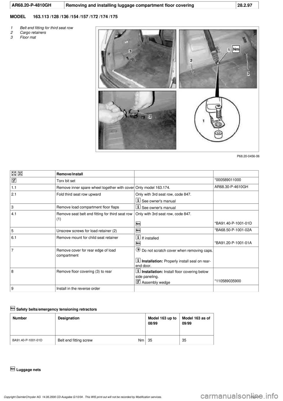
P68.20-0456-06
1
Belt end fitting for third seat row
2
Cargo retainers
3
Floor mat
Remove/install
Torx bit set
*000589011000
1.1
Remove inner spare wheel together with cover
Only model 163.174.
AR68.30-P-4610GH
2.1
Fold third seat row upward
Only with 3rd seat row, code 847.
See owner's manual
3
Remove load compartment floor flaps
See owner's manual
4.1
Remove seat belt end fitting for third seat row
(1)
Only with 3rd seat row, code 847.
*BA91.40-P-1001-01D
5
Unscrew screws for load retainer (2)
*BA68.50-P-1001-02A
6.1
Remove mount for child seat retainer
If installed
*BA91.20-P-1001-01A
7
Remove cover for rear edge of load
compartment
Do not scratch cover when removing caps.
Installation:
Properly install seal on rear-
end door.
8
Remove floor covering (3) to rear
Installation:
Install floor covering below
side paneling.
Assembly wedge
*110589035900
9
Install in the reverse order
Safety belts/emergency tensioning retractors
Number
Designation
Model 163 up to
08/99
Model 163 as of
09/99
BA91.40-P-1001-01DBelt end fitting screw
Nm
3535
Luggage nets
Copyright DaimlerChrysler AG 14.06.2006 CD-Ausgabe G/10/04 . This WIS print-out will not be recorde
d by Modification services.
Page 1
Page 3777 of 4133

AR40.10-P-1030A
Replace tire
27.1.95
MODELS
124, 129, 140, 163, 168, 170, 171, 202, 203, 208, 209, 210, 211, 215, 220, 230, 240
MODEL
414
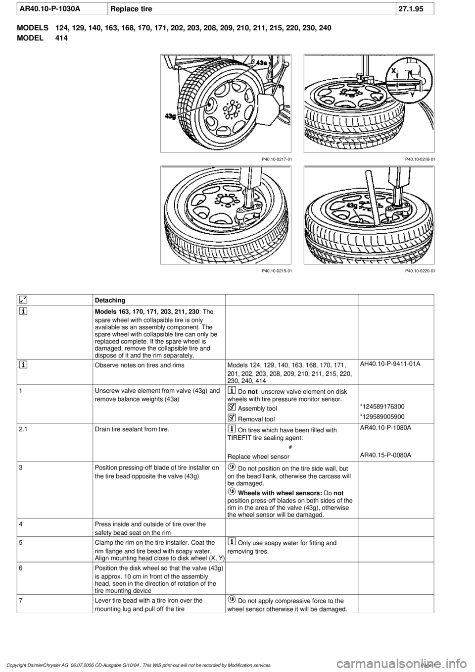
P40.10-0218-01
P40.10-0217-01
P40.10-0219-01 P40.10-0220-01
Detaching
Models 163, 170, 171, 203, 211, 230
: The
spare wheel with collapsible tire is only
available as an assembly component. The
spare wheel with collapsible tire can only be
replaced complete. If the spare wheel is
damaged, remove the collapsible tire and
dispose of it and the rim separately.
Observe notes on tires and rims
Models 124, 129, 140, 163, 168, 170, 171,
201, 202, 203, 208, 209, 210, 211, 215, 220,
230, 240, 414
AH40.10-P-9411-01A
1
Unscrew valve element from valve (43g) and
remove balance weights (43a)
Do
not
unscrew valve element on disk
wheels with tire pressure monitor sensor.
Assembly tool
*124589176300
Removal tool
*129589005900
2.1
Drain tire sealant from tire.
On tires which have been filled with
TIREFIT tire sealing agent:
#
AR40.10-P-1080A
Replace wheel sensor
AR40.15-P-0080A
3
Position pressing-off blade of tire installer on
the tire bead opposite the valve (43g)
Do not position on the tire side wall, but
on the bead flank, otherwise the carcass will
be damaged.
Wheels with wheel sensors:
Do
not
position press-off blades on both sides of the
rim in the area of the valve (43g), otherwise
the wheel sensor will be damaged.
4
Press inside and outside of tire over the
safety bead seat on the rim
5
Clamp the rim on the tire installer. Coat the
rim flange and tire bead with soapy water.
Align mounting head close to disk wheel (X, Y)
Only use soapy water for fitting and
removing tires.
6
Position the disk wheel so that the valve (43g)
is approx. 10 cm in front of the assembly
head, seen in the direction of rotation of the
tire mounting device
7
Lever tire bead with a tire iron over the
mounting lug and pull off the tire
Do not apply compressive force to the
wheel sensor otherwise it will be damaged.
Copyright DaimlerChrysler AG 06.07.2006 CD-Ausgabe G/10/04 . This WIS print-out will not be recorde
d by Modification services.
Page 1
Page 3838 of 4133
AR68.30-P-4610GH
Removing and installing spare wheel cover
28.4.99
MODEL
163.174
P68.30-2161-06
1
Spare wheel cover front section
2
Retaining straps
3
Electric air pump
4
Screws
5
Spare wheel mount
6
Bracket
7
Screws
Removal, installation
1
Remove cargo space cover
See Owner's Manual.
2
Loosen retaining straps (2) and remove spare
wheel cover front section (1)
3
Remove spare wheel
*BA40.10-P-1002-01A
4
Remove electric air pump (3)
5
Unscrew screws (4) and remove spare wheel
mount (5)
6
Remove bracket (6)
Turn in clockwise direction until bracket
(6) releases at D-pillar.
7
Remove rear wall on spare wheel cover
2 screws.
8
Install in opposite order
Wheels
Number
Designation
Model
163.174
BA40.10-P-1002-01A
Bolt for spare wheel on inside of spare wheel mount
Nm
50
Copyright DaimlerChrysler AG 14.06.2006 CD-Ausgabe G/10/04 . This WIS print-out will not be recorde
d by Modification services.
Page 1
Page 3839 of 4133
AR68.30-P-4610GH
Removing and installing spare wheel cover
28.4.99
MODEL
163.174
P68.30-2161-06
1
Spare wheel cover front section
2
Retaining straps
3
Electric air pump
4
Screws
5
Spare wheel mount
6
Bracket
7
Screws
Removal, installation
1
Remove cargo space cover
See Owner's Manual.
2
Loosen retaining straps (2) and remove spare
wheel cover front section (1)
3
Remove spare wheel
*BA40.10-P-1002-01A
4
Remove electric air pump (3)
5
Unscrew screws (4) and remove spare wheel
mount (5)
6
Remove bracket (6)
Turn in clockwise direction until bracket
(6) releases at D-pillar.
7
Remove rear wall on spare wheel cover
2 screws.
8
Install in opposite order
Wheels
Number
Designation
Model
163.174
BA40.10-P-1002-01A
Bolt for spare wheel on inside of spare wheel mount
Nm
50
Copyright DaimlerChrysler AG 17.05.2006 CD-Ausgabe G/10/04 . This WIS print-out will not be recorde
d by Modification services.
Page 1
Page 3840 of 4133
AR68.30-P-4610GH
Removing and installing spare wheel cover
28.4.99
MODEL
163.174
P68.30-2161-06
1
Spare wheel cover front section
2
Retaining straps
3
Electric air pump
4
Screws
5
Spare wheel mount
6
Bracket
7
Screws
Removal, installation
1
Remove cargo space cover
See Owner's Manual.
2
Loosen retaining straps (2) and remove spare
wheel cover front section (1)
3
Remove spare wheel
*BA40.10-P-1002-01A
4
Remove electric air pump (3)
5
Unscrew screws (4) and remove spare wheel
mount (5)
6
Remove bracket (6)
Turn in clockwise direction until bracket
(6) releases at D-pillar.
7
Remove rear wall on spare wheel cover
2 screws.
8
Install in opposite order
Wheels
Number
Designation
Model
163.174
BA40.10-P-1002-01A
Bolt for spare wheel on inside of spare wheel mount
Nm
50
Copyright DaimlerChrysler AG 17.05.2006 CD-Ausgabe G/10/04 . This WIS print-out will not be recorde
d by Modification services.
Page 1
Page 3909 of 4133

1998-2005 SUSPENSION
Suspension - 163 Chassis
GENERAL INFORMATION
GENERAL NOTES ON WORKING ON VEHICLES WITH LEVEL CONTROL/ADS - AH32.00-P-0002-01A
All models with code 216b, 216c, 217a, 480
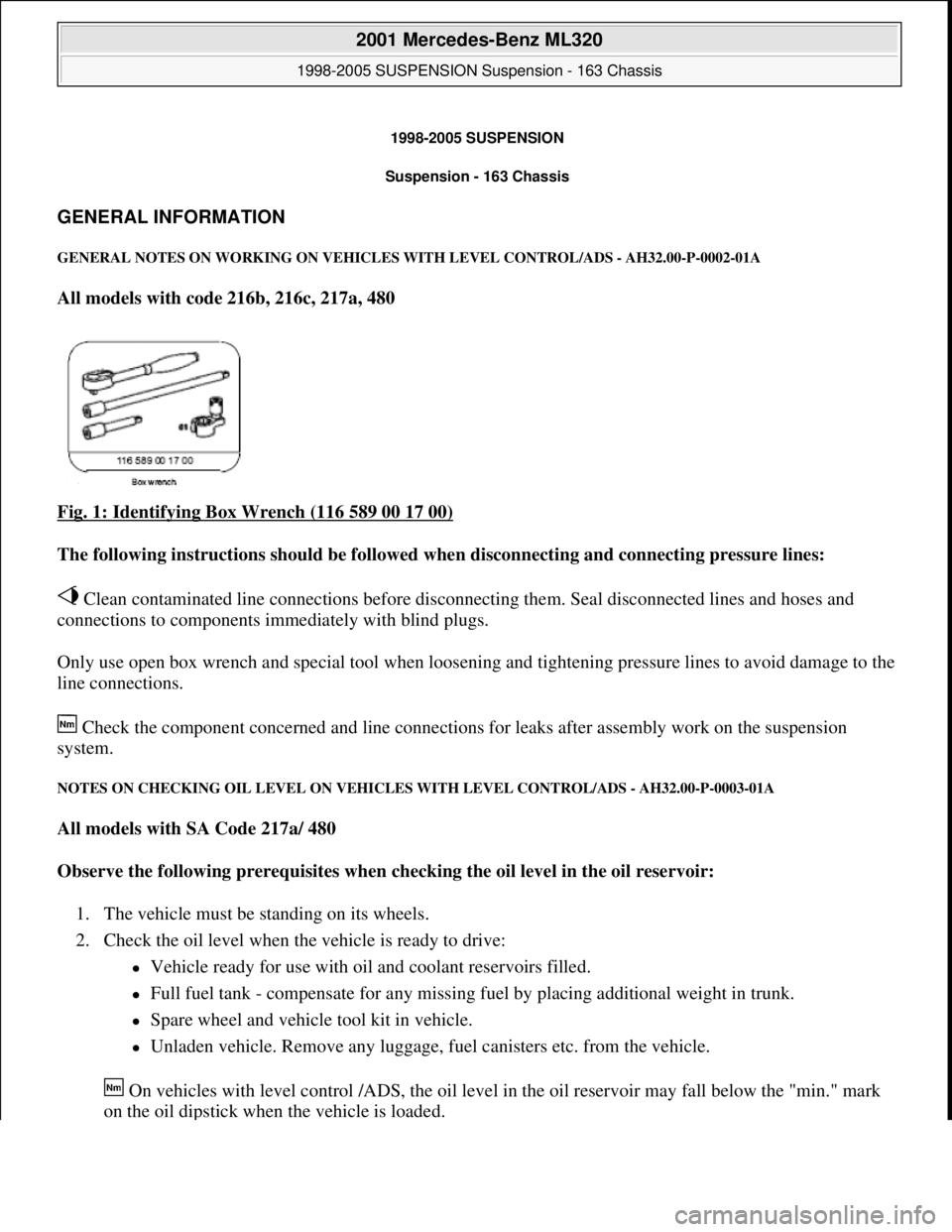
Fig. 1: Identifying Box Wrench (116 589 00 17 00)
The following instructions should be followed when disconnecting and connecting pressure lines:
Clean contaminated line connections before disconnecting them. Seal disconnected lines and hoses and
connections to components immediately with blind plugs.
Only use open box wrench and special tool when loosening and tightening pressure lines to avoid damage to the
line connections.
Check the component concerned and line connections for leaks after assembly work on the suspension
system.
NOTES ON CHECKING OIL LEVEL ON VEHICLES WITH LEVEL CONTROL/ADS - AH32.00-P-0003-01A
All models with SA Code 217a/ 480
Observe the following prerequisites when checking the oil level in the oil reservoir:
1. The vehicle must be standing on its wheels.
2. Check the oil level when the vehicle is ready to drive:
Vehicle ready for use with oil and coolant reservoirs filled.
Full fuel tank - compensate for any missing fuel by placing additional weight in trunk.
Spare wheel and vehicle tool kit in vehicle.
Unladen vehicle. Remove any luggage, fuel canisters etc. from the vehicle.
On vehicles with level control /ADS, the oil level in the oil reservoir may fall below the "min." mark
on the oil dipstick when the vehicle is loaded.
2001 Mercedes-Benz ML320
1998-2005 SUSPENSION Suspension - 163 Chassis
2001 Mercedes-Benz ML320
1998-2005 SUSPENSION Suspension - 163 Chassis
me
Saturday, October 02, 2010 3:37:35 PMPage 1 © 2006 Mitchell Repair Information Company, LLC.
me
Saturday, October 02, 2010 3:37:38 PMPage 1 © 2006 Mitchell Repair Information Company, LLC.