1997 MERCEDES-BENZ ML320 spare wheel
[x] Cancel search: spare wheelPage 2145 of 4133
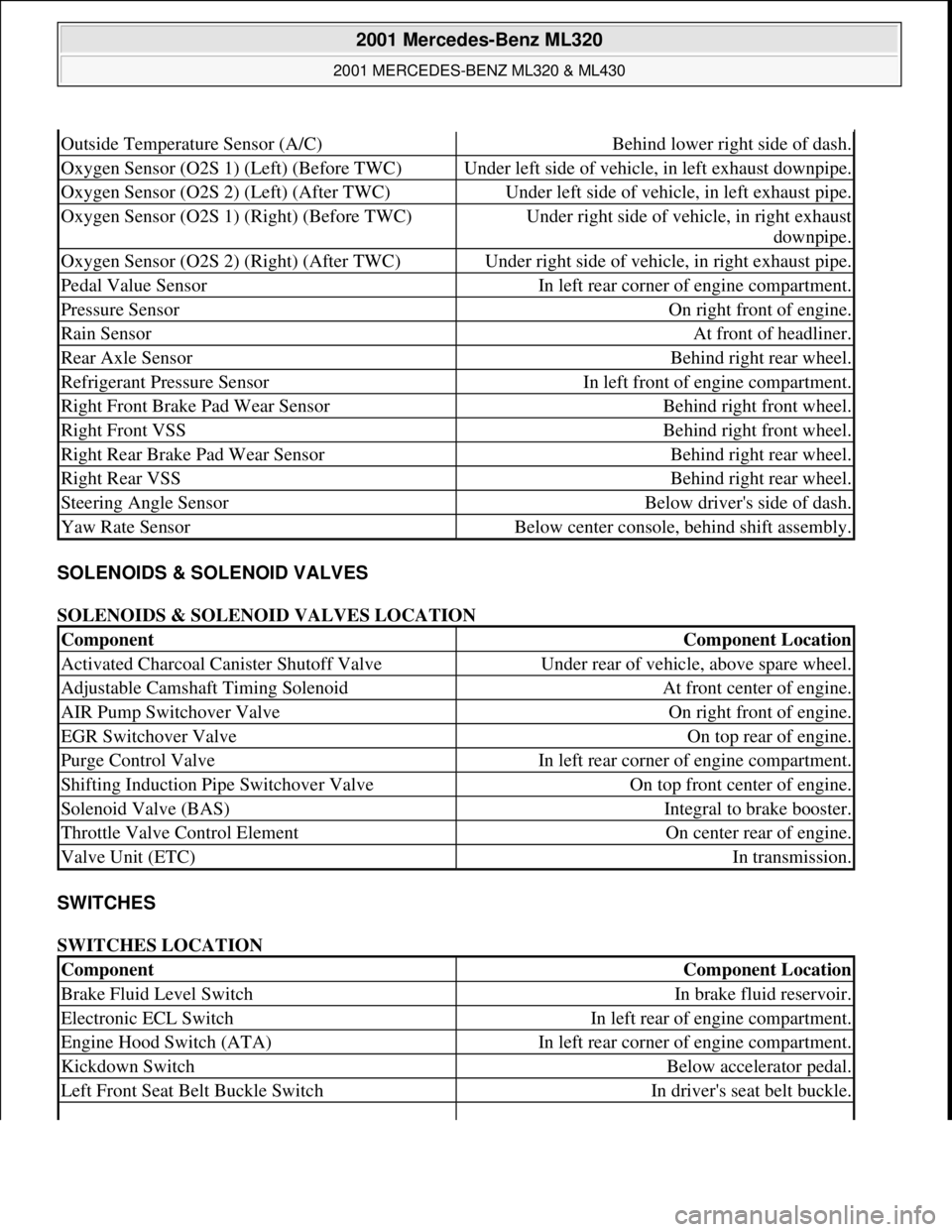
SOLENOIDS & SOLENOID VALVES
SOLENOIDS & SOLENOID VALVES LOCATION
SWITCHES
SWITCHES LOCATION
Outside Temperature Sensor (A/C)Behind lower right side of dash.
Oxygen Sensor (O2S 1) (Left) (Before TWC)Under left side of vehicle, in left exhaust downpipe.
Oxygen Sensor (O2S 2) (Left) (After TWC)Under left side of vehicle, in left exhaust pipe.
Oxygen Sensor (O2S 1) (Right) (Before TWC)Under right side of vehicle, in right exhaust
downpipe.
Oxygen Sensor (O2S 2) (Right) (After TWC)Under right side of vehicle, in right exhaust pipe.
Pedal Value SensorIn left rear corner of engine compartment.
Pressure SensorOn right front of engine.
Rain SensorAt front of headliner.
Rear Axle SensorBehind right rear wheel.
Refrigerant Pressure SensorIn left front of engine compartment.
Right Front Brake Pad Wear SensorBehind right front wheel.
Right Front VSSBehind right front wheel.
Right Rear Brake Pad Wear SensorBehind right rear wheel.
Right Rear VSSBehind right rear wheel.
Steering Angle SensorBelow driver's side of dash.
Yaw Rate SensorBelow center console, behind shift assembly.
ComponentComponent Location
Activated Charcoal Canister Shutoff ValveUnder rear of vehicle, above spare wheel.
Adjustable Camshaft Timing SolenoidAt front center of engine.
AIR Pump Switchover ValveOn right front of engine.
EGR Switchover ValveOn top rear of engine.
Purge Control ValveIn left rear corner of engine compartment.
Shifting Induction Pipe Switchover ValveOn top front center of engine.
Solenoid Valve (BAS)Integral to brake booster.
Throttle Valve Control ElementOn center rear of engine.
Valve Unit (ETC)In transmission.
ComponentComponent Location
Brake Fluid Level SwitchIn brake fluid reservoir.
Electronic ECL SwitchIn left rear of engine compartment.
Engine Hood Switch (ATA)In left rear corner of engine compartment.
Kickdown SwitchBelow accelerator pedal.
Left Front Seat Belt Buckle SwitchIn driver's seat belt buckle.
2001 Mercedes-Benz ML320
2001 MERCEDES-BENZ ML320 & ML430
me
Saturday, October 02, 2010 3:21:17 PMPage 5 © 2006 Mitchell Repair Information Company, LLC.
Page 2609 of 4133

Remove, Install
Danger!
Risk of explosion
from fuel igniting,
risk of
poisoning
from inhaling and swallowing fuel
as well as
risk of injury
to eyes and skin
from contact with fuel.
Fire, sparks, open flames or smoking
forbidden.
Pour fuels only into suitable and appropriately
marked containers.
Wear protective clothing when handling fuel.
AS47.00-Z-0001-01A
1
Drain fuel tank
Via fuel pump. NOT for model 163.113/128.
AR47.10-P-4001GH
If fuel pump faulty, and model 163.113/128.
AR47.10-P-4000GH
*BF47.10-P-1001-01A
2
Unscrew filler cap (2) and detach from filler
cap attachment (4)
3.1
Remove left seat of 3rd seat row
If installed. See owner's manual
4
Unclip cover of left-hand side panel (1)
5.1
Detach fuel lines of expansion reservoir and
separate from filler neck
As of VIN A289565. NOT for model
163.113/128.
6
Detach fuel filler neck from guide funnel
Installation:
Check O-ring and replace if
necessary. Ensure that the bayonet-lock
remains above
the pressure sensor.
Ensure it is correctly located when installed.
Open bayonet lock (3) to do this.
7
Pull filler neck through toward interior
Screw on cap again in order to avoid fuel
flowing out.
8.1
Remove fuel tank pressure sensor (B4/3)
Only USA version
AR47.10-P-8022GH
9.1
Detach bolted connection of fuel tank filler
neck/ground (X36/4) from filler neck
NOT for model 163.113/128.
10.1
Cut cable strap for retaining clips of fuel lines
at filler neck and remove retaining clips
As of VIN A289565. NOT for model
163.113/128.
Danger!
Risk of fatal accident
from vehicle slipping
or toppling off the lift platform
Align vehicle between the columns of lifting
platform and position the four support plates
below the support strongpoints specified by
the vehicle manufacturer.
AS00.00-Z-0010-01A
11
Place the vehicle on lifting platform
AR00.60-P-1000GH
12
Separate rubber seal (5) from underside of
vehicle and remove filler neck from interior
Do not damage fuel lines at filler neck.
13
Remove left rear wheel
e
Removing and installing wheels, rotating if
necessary
AP40.10-P-4050GH
14
Remove spare wheel and spare wheel carrier
complete
NOT in the case of spare wheel
holder/spare wheel, code 849.
15
Cut a large safety cable strap for filler neck at
bracket on longitudinal frame member
16
Remove bracket from longitudinal frame
member
17
Disconnect connection for regeneration (77/2)
and fresh air connection (77/4) on activated
charcoal canister (77)
Installation
: Connect up lines as per
connection diagram:
#
Engine 111
AR47.30-P-8212-01GJ
Engines 112, 113
AR47.30-P-8212-01GI
Engines 112, 113 version
I
AR47.30-P-8212-01GH
Charcoal canister and fuel tank form a
single unit.
NOT for model 163.113/128.
18
Detach vent hose
At rear differential to rear of activated
charcoal reservoir.
19
Remove rear exhaust system heat shield.
Do not damage boot at rear axle shaft.
20
Disconnect rear propeller shaft at differential
Installation:
Install new self-locking bolts.
Tie up propeller shaft e.g. using welding
wire
Heat bolts with hot air fan to facilitate
removing. Mark propeller shaft and differential
gear flange for correct installed position.
*BA41.10-P-1002-01C
Copyright DaimlerChrysler AG 28.05.2006 CD-Ausgabe G/10/04 . This WIS print-out will not be recorde
d by Modification services.
Page 2
Page 3056 of 4133
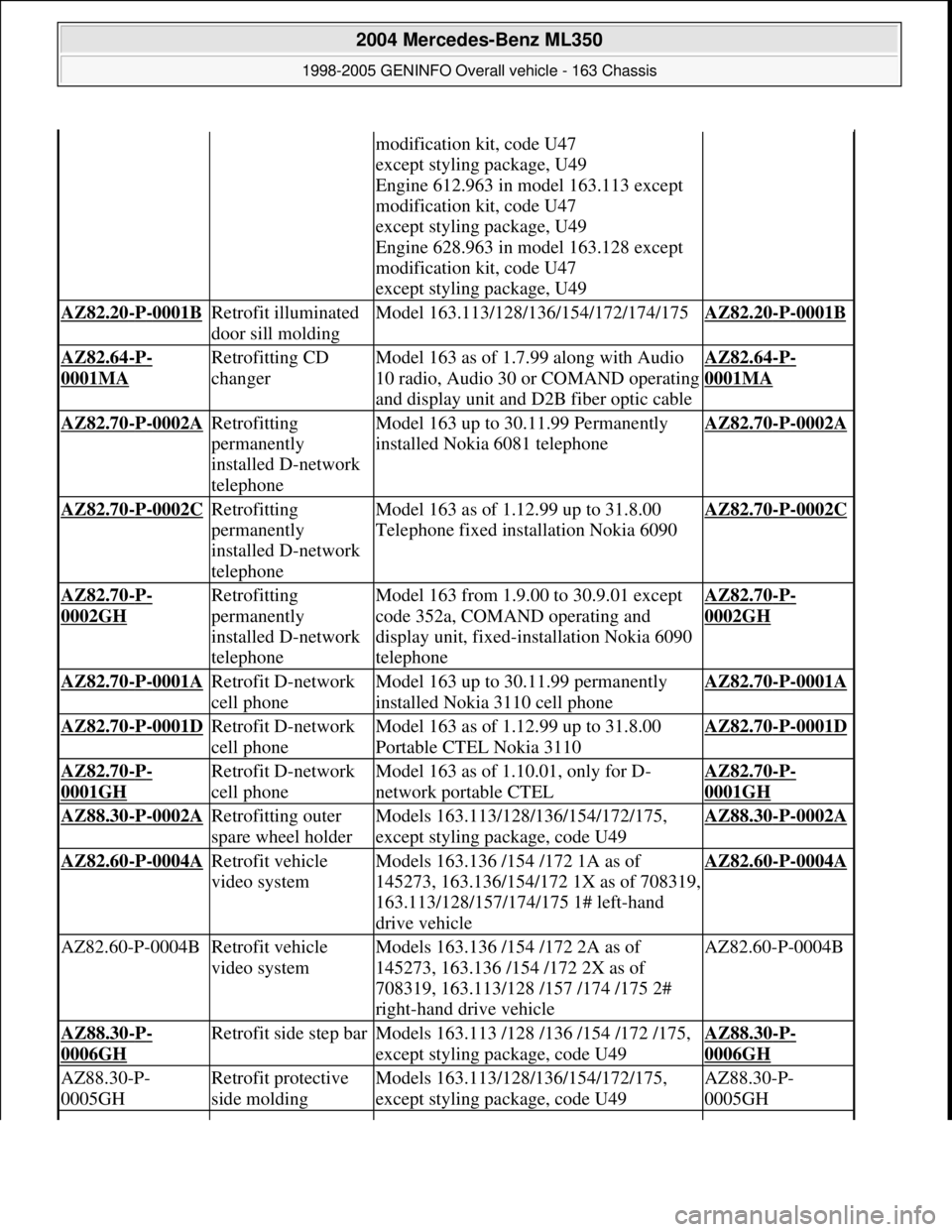
modification kit, code U47
except styling package, U49
Engine 612.963 in model 163.113 except
modification kit, code U47
except styling package, U49
Engine 628.963 in model 163.128 except
modification kit, code U47
except styling package, U49
AZ82.20-P-0001B Retrofit illuminated
door sill moldingModel 163.113/128/136/154/172/174/175AZ82.20-P-0001B
AZ82.64-P-
0001MA
Retrofitting CD
changerModel 163 as of 1.7.99 along with Audio
10 radio, Audio 30 or COMAND operating
and display unit and D2B fiber optic cableAZ82.64-P-
0001MA
AZ82.70-P-0002A Retrofitting
permanently
installed D-network
telephoneModel 163 up to 30.11.99 Permanently
installed Nokia 6081 telephoneAZ82.70-P-0002A
AZ82.70-P-0002C Retrofitting
permanently
installed D-network
telephoneModel 163 as of 1.12.99 up to 31.8.00
Telephone fixed installation Nokia 6090AZ82.70-P-0002C
AZ82.70-P-
0002GH
Retrofitting
permanently
installed D-network
telephoneModel 163 from 1.9.00 to 30.9.01 except
code 352a, COMAND operating and
display unit, fixed-installation Nokia 6090
telephoneAZ82.70-P-
0002GH
AZ82.70-P-0001A Retrofit D-network
cell phoneModel 163 up to 30.11.99 permanently
installed Nokia 3110 cell phoneAZ82.70-P-0001A
AZ82.70-P-0001D Retrofit D-network
cell phoneModel 163 as of 1.12.99 up to 31.8.00
Portable CTEL Nokia 3110AZ82.70-P-0001D
AZ82.70-P-
0001GH
Retrofit D-network
cell phoneModel 163 as of 1.10.01, only for D-
network portable CTELAZ82.70-P-
0001GH
AZ88.30-P-0002A Retrofitting outer
spare wheel holderModels 163.113/128/136/154/172/175,
except styling package, code U49AZ88.30-P-0002A
AZ82.60-P-0004A Retrofit vehicle
video systemModels 163.136 /154 /172 1A as of
145273, 163.136/154/172 1X as of 708319,
163.113/128/157/174/175 1# left-hand
drive vehicleAZ82.60-P-0004A
AZ82.60-P-0004BRetrofit vehicle
video systemModels 163.136 /154 /172 2A as of
145273, 163.136 /154 /172 2X as of
708319, 163.113/128 /157 /174 /175 2#
right-hand drive vehicleAZ82.60-P-0004B
AZ88.30-P-
0006GH
Retrofit side step barModels 163.113 /128 /136 /154 /172 /175,
except styling package, code U49AZ88.30-P-
0006GH
AZ88.30-P-
0005GHRetrofit protective
side moldingModels 163.113/128/136/154/172/175,
except styling package, code U49AZ88.30-P-
0005GH
2004 Mercedes-Benz ML350
1998-2005 GENINFO Overall vehicle - 163 Chassis
me
Saturday, October 02, 2010 3:47:52 PMPage 411 © 2006 Mitchell Repair Information Company, LLC.
Page 3058 of 4133
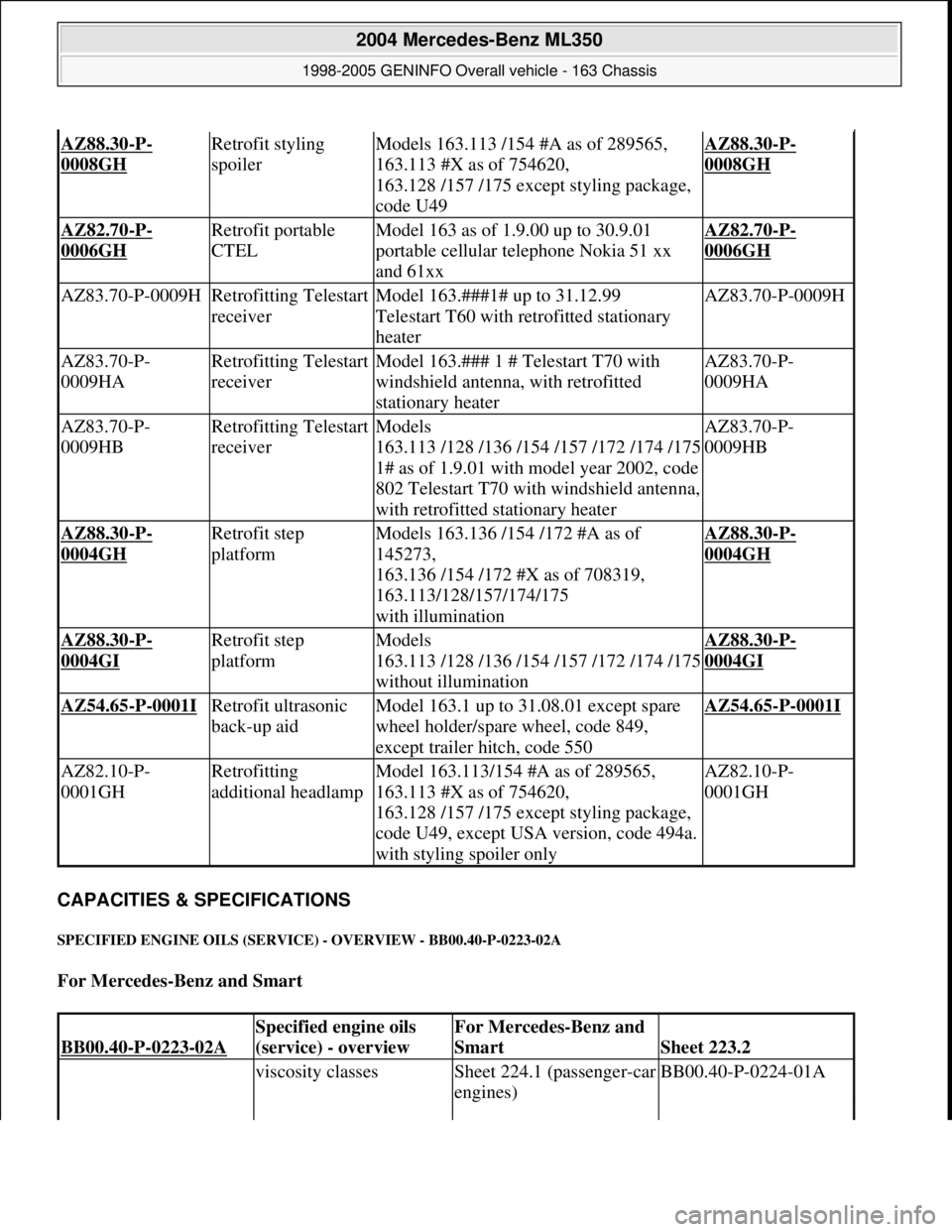
CAPACITIES & SPECIFICATIONS
SPECIFIED ENGINE OILS (SERVICE) - OVERVIEW - BB00.40-P-0223-02A
For Mercedes-Benz and Smart
AZ88.30-P-
0008GH
Retrofit styling
spoilerModels 163.113 /154 #A as of 289565,
163.113 #X as of 754620,
163.128 /157 /175 except styling package,
code U49AZ88.30-P-
0008GH
AZ82.70-P-
0006GH
Retrofit portable
CTELModel 163 as of 1.9.00 up to 30.9.01
portable cellular telephone Nokia 51 xx
and 61xxAZ82.70-P-
0006GH
AZ83.70-P-0009HRetrofitting Telestart
receiverModel 163.###1# up to 31.12.99
Telestart T60 with retrofitted stationary
heaterAZ83.70-P-0009H
AZ83.70-P-
0009HARetrofitting Telestart
receiverModel 163.### 1 # Telestart T70 with
windshield antenna, with retrofitted
stationary heaterAZ83.70-P-
0009HA
AZ83.70-P-
0009HBRetrofitting Telestart
receiverModels
163.113 /128 /136 /154 /157 /172 /174 /175
1# as of 1.9.01 with model year 2002, code
802 Telestart T70 with windshield antenna,
with retrofitted stationary heaterAZ83.70-P-
0009HB
AZ88.30-P-
0004GH
Retrofit step
platformModels 163.136 /154 /172 #A as of
145273,
163.136 /154 /172 #X as of 708319,
163.113/128/157/174/175
with illuminationAZ88.30-P-
0004GH
AZ88.30-P-
0004GI
Retrofit step
platformModels
163.113 /128 /136 /154 /157 /172 /174 /175
without illuminationAZ88.30-P-
0004GI
AZ54.65-P-0001I Retrofit ultrasonic
back-up aidModel 163.1 up to 31.08.01 except spare
wheel holder/spare wheel, code 849,
except trailer hitch, code 550AZ54.65-P-0001I
AZ82.10-P-
0001GHRetrofitting
additional headlampModel 163.113/154 #A as of 289565,
163.113 #X as of 754620,
163.128 /157 /175 except styling package,
code U49, except USA version, code 494a.
with styling spoiler onlyAZ82.10-P-
0001GH
BB00.40-P-0223-02A
Specified engine oils
(service) - overviewFor Mercedes-Benz and
Smart
Sheet 223.2
viscosity classesSheet 224.1 (passenger-car
engines)BB00.40-P-0224-01A
2004 Mercedes-Benz ML350
1998-2005 GENINFO Overall vehicle - 163 Chassis
me
Saturday, October 02, 2010 3:47:52 PMPage 413 © 2006 Mitchell Repair Information Company, LLC.
Page 3485 of 4133

Rims
D
When changing wheels, for instance, when replacing steel
wheels with light-alloy rims, ensure that the wheel bolts
required for the spare wheel are stored in a clearly visible
location.
D
Since December 1994 models 202 and 124 with special
equipment light alloy disk wheels, are supplied with a sheet
steel spare wheel instead of a light alloy spare wheel. The
necessary wheel bolts are included with the steel spare wheel.
D
Only use approved Mercedes-Benz rims of the same version.
D
Reinforced steel rims are identified by a sticker on the wheel
disc.
D
The wheel bolts on steel and light-alloy rims should always be
tightened to the specified tightening torque using a torque
wrench.
It is not necessary to retorque the lug bolts after approximately
100 to 500 km.
D
The seat for the tire bead must display no corrosion marks.
D
Before inserting a new rubber valve, clean the contact surfaces
on the disk wheel.
On sheet steel-disk wheel wheel trims must be fitted to support
the rubber valve.
Damaged or deformed rims must not be repaired.
Tire pressure monitor
D
Before replacing a tire, check the date of manufacturer of the
wheel sensor: wheel sensors which are more than 5 years old
must be replaced.
D
Use STAR DIAGNOSIS to read out the actual values of the tire
pressure monitor. Check the remaining life of the wheel sensor
battery, replace the wheel sensor if necessary.
Copyright DaimlerChrysler AG 06.07.2006 CD-Ausgabe G/10/04 . This WIS print-out will not be recorde
d by Modification services.
Page 2
Page 3533 of 4133
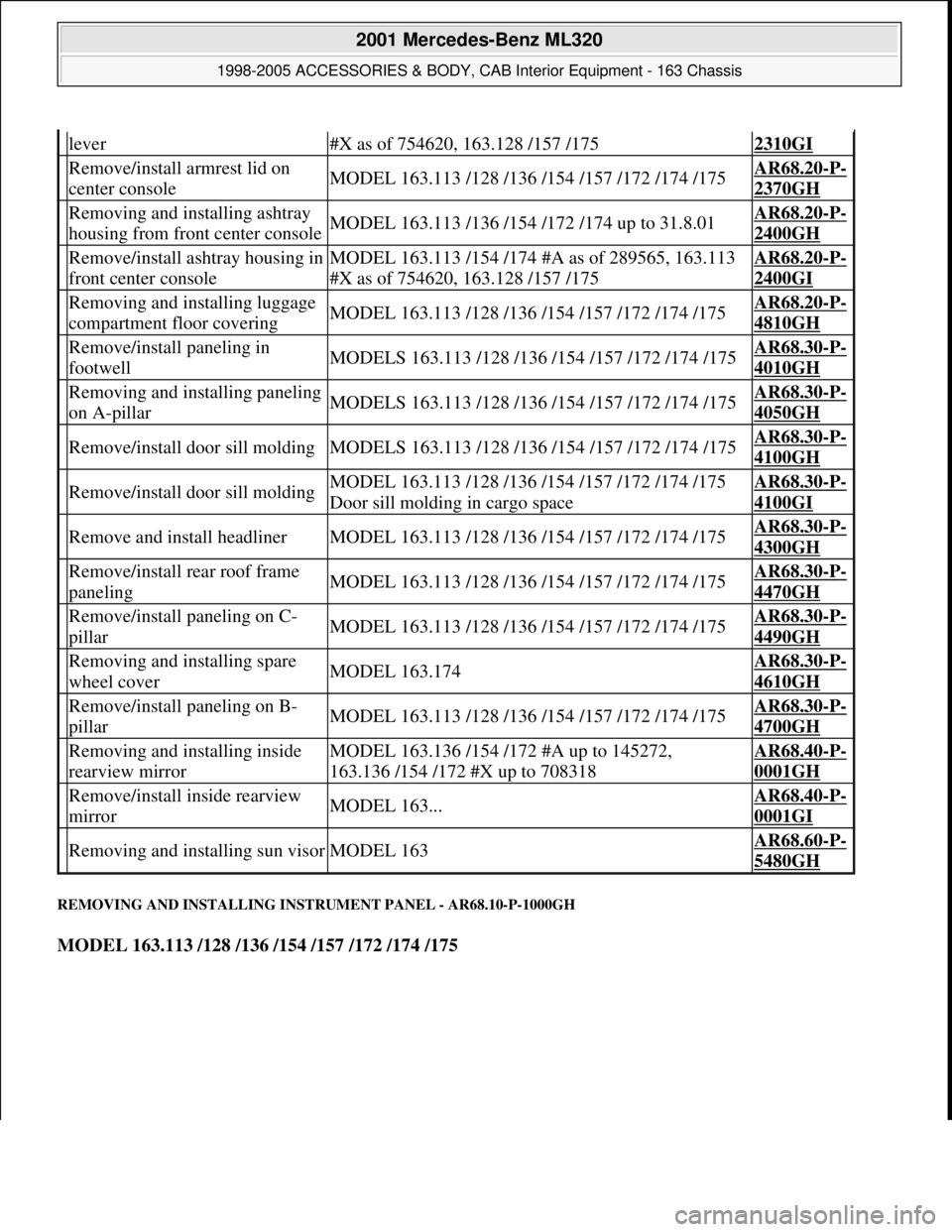
REMOVING AND INSTALLING INSTRUMENT PANEL - AR68.10-P-1000GH
MODEL 163.113 /128 /136 /154 /157 /172 /174 /175
lever#X as of 754620, 163.128 /157 /1752310GI
Remove/install armrest lid on
center consoleMODEL 163.113 /128 /136 /154 /157 /172 /174 /175AR68.20-P-
2370GH
Removing and installing ashtray
housing from front center consoleMODEL 163.113 /136 /154 /172 /174 up to 31.8.01AR68.20-P-
2400GH
Remove/install ashtray housing in
front center consoleMODEL 163.113 /154 /174 #A as of 289565, 163.113
#X as of 754620, 163.128 /157 /175AR68.20-P-
2400GI
Removing and installing luggage
compartment floor coveringMODEL 163.113 /128 /136 /154 /157 /172 /174 /175AR68.20-P-
4810GH
Remove/install paneling in
footwellMODELS 163.113 /128 /136 /154 /157 /172 /174 /175AR68.30-P-
4010GH
Removing and installing paneling
on A-pillarMODELS 163.113 /128 /136 /154 /157 /172 /174 /175AR68.30-P-
4050GH
Remove/install door sill moldingMODELS 163.113 /128 /136 /154 /157 /172 /174 /175AR68.30-P-
4100GH
Remove/install door sill moldingMODEL 163.113 /128 /136 /154 /157 /172 /174 /175
Door sill molding in cargo spaceAR68.30-P-
4100GI
Remove and install headlinerMODEL 163.113 /128 /136 /154 /157 /172 /174 /175AR68.30-P-
4300GH
Remove/install rear roof frame
panelingMODEL 163.113 /128 /136 /154 /157 /172 /174 /175AR68.30-P-
4470GH
Remove/install paneling on C-
pillarMODEL 163.113 /128 /136 /154 /157 /172 /174 /175AR68.30-P-
4490GH
Removing and installing spare
wheel coverMODEL 163.174AR68.30-P-
4610GH
Remove/install paneling on B-
pillarMODEL 163.113 /128 /136 /154 /157 /172 /174 /175AR68.30-P-
4700GH
Removing and installing inside
rearview mirrorMODEL 163.136 /154 /172 #A up to 145272,
163.136 /154 /172 #X up to 708318AR68.40-P-
0001GH
Remove/install inside rearview
mirrorMODEL 163...AR68.40-P-
0001GI
Removing and installing sun visorMODEL 163AR68.60-P-
5480GH
2001 Mercedes-Benz ML320
1998-2005 ACCESSORIES & BODY, CAB Interior Equipment - 163 Chassis
me
Saturday, October 02, 2010 3:35:21 PMPage 15 © 2006 Mitchell Repair Information Company, LLC.
Page 3574 of 4133
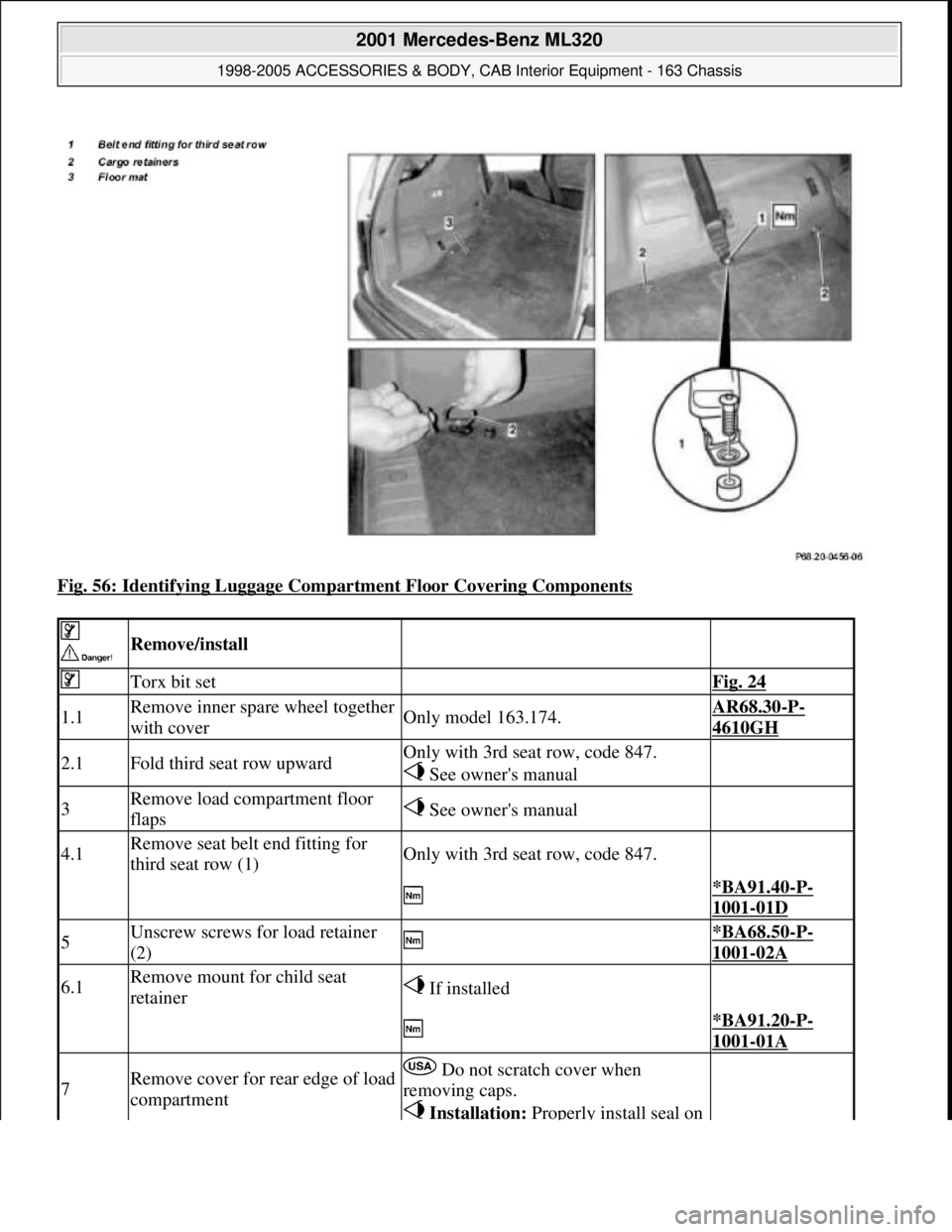
Fig. 56: Identifying Luggage Compartment Floor Covering Components
Remove/install
Torx bit set Fig. 24
1.1Remove inner spare wheel together
with coverOnly model 163.174.AR68.30-P-
4610GH
2.1Fold third seat row upwardOnly with 3rd seat row, code 847.
See owner's manual
3Remove load compartment floor
flaps See owner's manual
4.1Remove seat belt end fitting for
third seat row (1)Only with 3rd seat row, code 847.
*BA91.40-P-
1001-01D
5Unscrew screws for load retainer
(2) *BA68.50-P-
1001-02A
6.1Remove mount for child seat
retainer If installed
*BA91.20-P-
1001-01A
7Remove cover for rear edge of load
compartment Do not scratch cover when
removing caps.
Installation: Properly install seal on
2001 Mercedes-Benz ML320
1998-2005 ACCESSORIES & BODY, CAB Interior Equipment - 163 Chassis
me
Saturday, October 02, 2010 3:35:22 PMPage 56 © 2006 Mitchell Repair Information Company, LLC.
Page 3586 of 4133
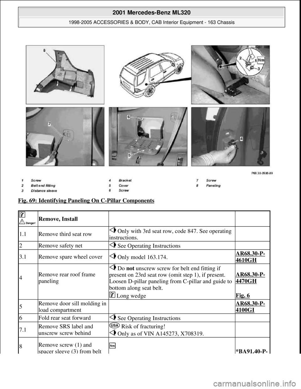
Fig. 69: Identifying Paneling On C-Pillar Components
Remove, Install
1.1Remove third seat row Only with 3rd seat row, code 847. See operating
instructions.
2Remove safety net See Operating Instructions
3.1Remove spare wheel cover Only model 163.174.AR68.30-P-
4610GH
4Remove rear roof frame
paneling
Do not unscrew screw for belt end fitting if
present on 23rd seat row (omit step 1), if present.
Loosen D-pillar paneling from C-pillar and guide to
bottom along seat belt.
AR68.30-P-
4470GH
Long wedgeFig. 6
5Remove door sill molding in
load compartment AR68.30-P-
4100GI
6Fold rear seat forward See Operating Instructions
7.1Remove SRS label and
unscrew screw behind Risk of fracturing!
Only as of VIN A145273, X708319.
8Remove screw (1) and
spacer sleeve (3) from belt *BA91.40-P-
2001 Mercedes-Benz ML320
1998-2005 ACCESSORIES & BODY, CAB Interior Equipment - 163 Chassis
me
Saturday, October 02, 2010 3:35:22 PMPage 68 © 2006 Mitchell Repair Information Company, LLC.