1997 MERCEDES-BENZ ML320 transmission
[x] Cancel search: transmissionPage 3757 of 4133

3.1
Remove viscous fan (1)
Engine 112.942 /970 and 113.942.
Right-hand thread!
AR20.40-P-5660C
3.2
Remove electric fan
Only Engine 113.965 /981.
AR20.40-P-5000GH
4.1
Pull off plate clamps of fan shroud (2)
Only for Engine 112.942, from 5/98.
5.1
Remove fan shroud (3)
Only for Engine 112.942 /970 und
113.942. Unscrew the bolts at bottom of fan
shroud for this step
Installation:
If installing a new radiator
with integral power steering pump oil cooler, a
new fan shroud is required if a radiator
without integral oil cooler was previously
installed.
6
Remove headlamp (7).
AR82.10-P-4730GH
7
Remove radiator crossmember (8)
AR62.30-P-2300GH
8
Detach coolant line (4, 6) and expansion
reservoir coolant line (5) at the radiator
Installation:
Replace the hose clamps on
the radiator fitting for the coolant hose, as
they could cause damage to the screw/thread.
Hose clamp
*BA20.20-P-1004-01A
9
Remove the rubber seal on radiator (9)
10.1
Remove oil line (return line of radiator
!
power steering pump expansion reservoir)
(18) and oil line (feed line of steering gear
!
radiator) (19)
From 5/98 only, seal off the connections.
Set of plugs
*129589009100
11
Unscrew ATF lines (10) at the radiator
Seal off the connections.
*BA20.20-P-1001-01A
*BA20.20-P-1003-01A
Set of plugs
*129589009100
12.1
Detach the connector from the fan and
remove the fan grille (11)
Only for Engine 112.942 /970 and 113.942.
13
Unscrew the condenser from the radiator
Do not disconnect the lines.
14
Remove fasteners (20) and damper rubber
(21)
The damper rubber (21) is designed to
prevent possible vibrations between the
condenser and radiator (15) during off-road
driving.
15
Remove air conditioning system fluid
reservoir (14) from the radiator
Place aside with the lines connected.
Detach the condenser from the radiator.
16
Remove radiator (15)
When installing, the spigots on the
radiator must be inserted in the rubber
grommets in the bottom crossmember.
Installation:
On Model 163.154 with
Engine 112.942 before VIN end number
043553, when installing a new radiator with
integral power steering pump oil cooler,
additional operations are required, if they
have not already been carried out:
#
v
Retrofit the bracket for the oil cooler line of
the power steering pump
SM46.30-P-0002A
k
Radiator with integral oil cooler for the power
steering pump
BT20.20-P-0001-01A
17
Detach air guides (12)
Replace the clamps on air guides (13).
18
Install in the reverse order
19
Pour in coolant
AR20.00-P-1142HA
20
Check the headlamp setting and correct if
necessary
e
Check and adjust the headlamp setting
AP82.10-P-8260GH
Danger!
Risk of accident
caused by vehicle starting
off when engine is running.
Risk of injury
caused by contusions and burns when
working in engine during starting procedure
Secure the vehicle to prevent it from moving.
Wear closed and snug-fitting work clothes.
Do not grasp hot or rotating parts.
AS00.00-Z-0005-01A
21
Check the oil level in the automatic
transmission and correct if necessary
AR27.00-P-0101A
22
Check the cooling system for leaks
AR20.00-P-1010HA
Radiator, coolant hoses
Copyright DaimlerChrysler AG 12.05.2006 CD-Ausgabe G/10/04 . This WIS print-out will not be recorde
d by Modification services.
Page 2
Page 3758 of 4133
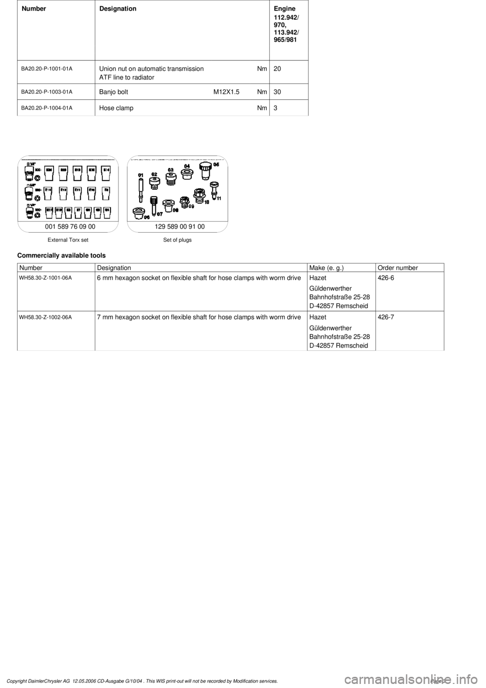
Number
Designation
Engine
112.942/
970,
113.942/
965/981
BA20.20-P-1001-01A
Union nut on automatic transmission
ATF line to radiatorNm
20
BA20.20-P-1003-01A
Banjo bolt
M12X1.5
Nm
30
BA20.20-P-1004-01A
Hose clamp
Nm
3
129 589 00 91 00
Set of plugs
External Torx set
001 589 76 09 00
Commercially available tools
Number
Designation
Make (e. g.)
Order number
WH58.30-Z-1001-06A
6 mm hexagon socket on flexible shaft for hose clamps with worm drive
Hazet
Güldenwerther
Bahnhofstraße 25-28
D-42857 Remscheid
426-6
WH58.30-Z-1002-06A
7 mm hexagon socket on flexible shaft for hose clamps with worm drive
Hazet
Güldenwerther
Bahnhofstraße 25-28
D-42857 Remscheid
426-7
Copyright DaimlerChrysler AG 12.05.2006 CD-Ausgabe G/10/04 . This WIS print-out will not be recorde
d by Modification services.
Page 3
Page 3852 of 4133
ENGINE 119.980 /981 /982 /985
ENGINE 120.982/983
ENGINE 137.970
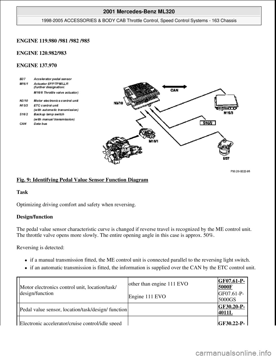
Fig. 9: Identifying Pedal Value Sensor Function Diagram
Task
Optimizing driving comfort and safety when reversing.
Design/function
The pedal value sensor characteristic curve is changed if reverse travel is recognized by the ME control unit.
The throttle valve opens more slowly. The entire opening angle in this case is approx. 50%.
Reversing is detected:
if a manual transmission fitted, the ME control unit is connected parallel to the reversing light switch.
if an automatic transmission is fitted, the information is supplied over the CAN by the ETC control unit.
Motor electronics control unit, location/task/
design/functionother than engine 111 EVOGF07.61-P-
5000F
Engine 111 EVOGF07.61-P-
5000GS
Pedal value sensor, location/task/design/ function GF30.20-P-
4011L
Electronic accelerator/cruise control/idle speed GF30.22-P-
2001 Mercedes-Benz ML320
1998-2005 ACCESSORIES & BODY CAB Throttle Control, Speed Control Systems - 163 Chassis
me
Saturday, October 02, 2010 3:36:27 PMPage 12 © 2006 Mitchell Repair Information Company, LLC.
Page 3853 of 4133
ELECTRONIC ACCELERATOR PEDAL EMERGENCY RUNNING MODE FUNCTION - GF30.20-P-4026E
ENGINE 104.941 /943 /944 /991 /994 as of 1/8/96
ENGINE 104.995
with CODE (494a) USA version
with CODE (807) Model year 1997
with CODE (808) Model year 1998
with CODE (498) as of Model year 97 Japanese version
ENGINE 111.921 /942 as of 1.9.98,
111.946 as of 1.6.98,
111.944/975 as of 1.8.96,
111.943 /947 /951 /952 /955 /956 /957 /958 /973 /982 /983
ENGINE 111.945
in MODEL 202.020 /080 as of 1.9.98,
208.335/435 as of 1.6.98
ENGINE 111.974
with CODE (494a) USA version
with CODE (807) Model year 1997
with CODE (808) Model year 1998
ENGINE
112.910 /911 /912 /913 /914 /916 /917 /920 /921 /922 /923 /940 /941 /942 /943 /944 /946 /947 /949 /953 /954 /9
5
control actuator location/task/design/function4010F
Throttle valve actuator, location/task/design/
functionEngine 111 EVOGF30.22-P-
4101GS
ETC control unit, location/task
Information on selector lever position
P/N and gear engaged in the case of
automatic transmission.
Transmission 722.6
GF27.19-P-
4012G
2001 Mercedes-Benz ML320
1998-2005 ACCESSORIES & BODY CAB Throttle Control, Speed Control Systems - 163 Chassis
me
Saturday, October 02, 2010 3:36:27 PMPage 13 © 2006 Mitchell Repair Information Company, LLC.
Page 3857 of 4133
different engine loads, e.g. power steering turned to full lock, engaging drive mode, switching on AC
compressor
different mixture, e.g. from activated charcoal canister if purging activated (depending on activated
charcoal charge)
Function
The actuator EFP/TPM/LLR (additional designation: throttle valve actuator) regulates the idling speed by
changing the throttle valve position. It is actuated by the ME-SFI control unit.
The ME-SFI control unit actuates the throttle valve motor (M16/1 m1) in line with the input signals received at
the ME-SFI control unit (N3/10).
Heating speed of the catalytic converter
In order to warm up the catalytic converter more rapidly to operating temperature, engine speed is increased in
the idle speed range to 1100 up to 1500 rpm for about 20 seconds after each starting procedure at coolant
temperatures of < 40 °C. When a Drive position is engaged, engine speed is immediately controlled to a lower
value.
Automatic transmission
When a drive position is engaged, a lower engine speed is controlled in order to reduce the creeping tendency o
f
the vehicle. The information "Drive position engaged/not engaged" is transmitted by the ETC control unit
(N15/3) over the CAN databus to the ME-SFI control unit.
Ignition angle
To assist the idle speed control, the ignition angle can be retarded by as much as 36° crank angle or advanced by
as much as 20° crank angle from the calculated specified value.
The control in the idle speed range by altering the ignition angle reacts more rapidly than altering the position o
f
the throttle valve.
The idling speed can be influenced with HHT or the STAR DIAGNOSIS.
AC compressor
In order to avoid engine speed dropping in the idle speed range when the AC compressor is engaged, the AC
push-button control unit (N19) or automatic air conditioning push-button control unit (N22) supplies a signal to
the ME-SFI control unit (as of approx. 6/96 over CAN) and the opening cross-section of the throttle valve is
enlarged.
When the air conditionin
g unit is switched on and the external temperature exceeds 35° C the idling speed on
2001 Mercedes-Benz ML320
1998-2005 ACCESSORIES & BODY CAB Throttle Control, Speed Control Systems - 163 Chassis
me
Saturday, October 02, 2010 3:36:27 PMPage 17 © 2006 Mitchell Repair Information Company, LLC.
Page 3859 of 4133
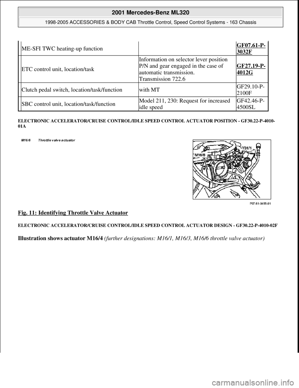
ELECTRONIC ACCELERATOR/CRUISE CONTROL/IDLE SPEED CONTROL ACTUATOR POSITION - GF30.22-P-4010-
01A
Fig. 11: Identifying Throttle Valve Actuator
ELECTRONIC ACCELERATOR/CRUISE CONTROL/IDLE SPEED CONTROL ACTUATOR DESIGN - GF30.22-P-4010-02F
Illustration shows actuator M16/4 (further designations: M16/1, M16/3, M16/6 throttle valve actuator)
ME-SFI TWC heating-up function GF07.61-P-
3032F
ETC control unit, location/task
Information on selector lever position
P/N and gear engaged in the case of
automatic transmission.
Transmission 722.6
GF27.19-P-
4012G
Clutch pedal switch, location/task/functionwith MTGF29.10-P-
2100F
SBC control unit, location/task/functionModel 211, 230: Request for increased
idle speedGF42.46-P-
4500SL
2001 Mercedes-Benz ML320
1998-2005 ACCESSORIES & BODY CAB Throttle Control, Speed Control Systems - 163 Chassis
me
Saturday, October 02, 2010 3:36:27 PMPage 19 © 2006 Mitchell Repair Information Company, LLC.
Page 3867 of 4133
Vehicles with EZS control unit without column sleeve module (MRM)
The signals from the push-button switch for the cruise control are detected by the control unit EIS and
transmitted to the CAN data bus.
Vehicles without EZS control unit
The signals from the cruise control switch are transmitted directly to the engine control unit.
Vehicles with manual transmission (MT)
Cruise control remains active during gear change, in other words the cruise control is not switched off when the
clutch is operated.
Traction systems control unit
Transmits the vehicle speed signal via CAN to the ME control unit.
CRUISE CONTROL SWITCH, LOCATION/TASK/DESIGN/FUNCTION - GF30.30-P-3100F
ENGINE 104 (except 104.98),
Motor electronics control unit, location/task/
design/functionother than engine 111 EVOGF07.61-P-
5000F
Engine 111 EVOGF07.61-P-
5000GS
Cruise control switch, location/task/design/
functionwith cruise control or Distronic GF30.30-P-
3100F
Variable cruise control switch, location/task/
design/functionwith cruise control or Distronic except
GF30.30-P-
3101A
Electronic accelerator/cruise control/idle speed
control actuator location/task/design/function GF30.22-P-
4010F
Throttle valve actuator, location/task/design/
functionEngine 111 EVOGF30.22-P-
4101GS
Stop lamp switch, location/task/function GF42.10-P-
4000A
Clutch pedal switch, location/task/functionwith MTGF29.10-P-
2100F
Variable speed limiter, functionAdditional cruise control function except
GF30.30-P-
3001A
ETC control unit, location/task
Transmits information about the selector
lever position P/N and the driving mode
selected via CAN.
Transmission 722.6
GF27.19-P-
4012G
2001 Mercedes-Benz ML320
1998-2005 ACCESSORIES & BODY CAB Throttle Control, Speed Control Systems - 163 Chassis
me
Saturday, October 02, 2010 3:36:27 PMPage 27 © 2006 Mitchell Repair Information Company, LLC.
Page 3870 of 4133
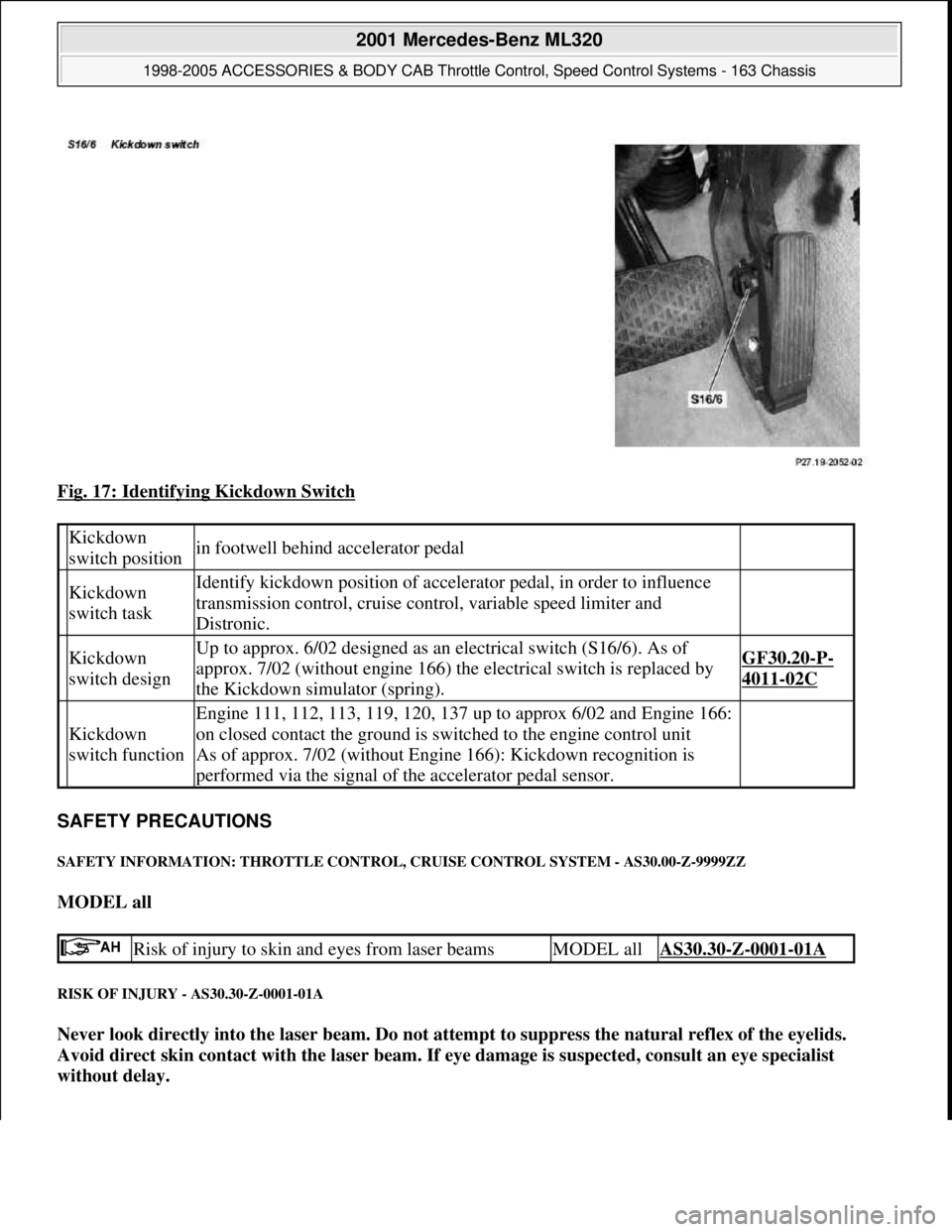
Fig. 17: Identifying Kickdown Switch
SAFETY PRECAUTIONS
SAFETY INFORMATION: THROTTLE CONTROL, CRUISE CONTROL SYSTEM - AS30.00-Z-9999ZZ
MODEL all
RISK OF INJURY - AS30.30-Z-0001-01A
Never look directly into the laser beam. Do not attempt to suppress the natural reflex of the eyelids.
Avoid direct skin contact with the laser beam. If eye damage is suspected, consult an eye specialist
without delay.
Kickdown
switch positionin footwell behind accelerator pedal
Kickdown
switch taskIdentify kickdown position of accelerator pedal, in order to influence
transmission control, cruise control, variable speed limiter and
Distronic.
Kickdown
switch designUp to approx. 6/02 designed as an electrical switch (S16/6). As of
approx. 7/02 (without engine 166) the electrical switch is replaced by
the Kickdown simulator (spring).GF30.20-P-
4011-02C
Kickdown
switch function
Engine 111, 112, 113, 119, 120, 137 up to approx 6/02 and Engine 166:
on closed contact the ground is switched to the engine control unit
As of approx. 7/02 (without Engine 166): Kickdown recognition is
performed via the signal of the accelerator pedal sensor.
Risk of injury to skin and eyes from laser beamsMODEL allAS30.30-Z-0001-01A
2001 Mercedes-Benz ML320
1998-2005 ACCESSORIES & BODY CAB Throttle Control, Speed Control Systems - 163 Chassis
me
Saturday, October 02, 2010 3:36:27 PMPage 30 © 2006 Mitchell Repair Information Company, LLC.