1997 MERCEDES-BENZ ML320 transmission
[x] Cancel search: transmissionPage 3465 of 4133
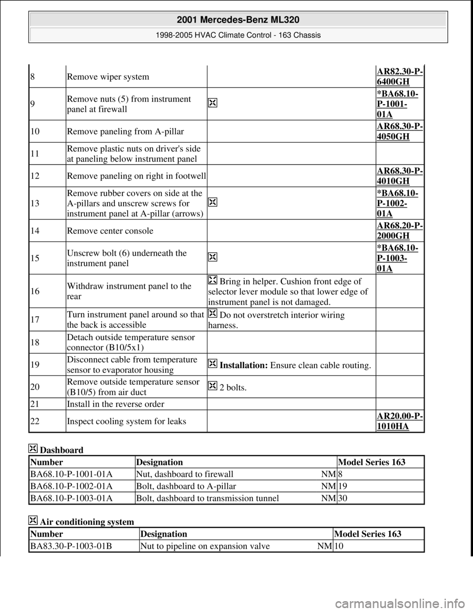
Dashboard
Air conditioning system
8Remove wiper system AR82.30-P-
6400GH
9Remove nuts (5) from instrument
panel at firewall
*BA68.10-
P-1001-
01A
10Remove paneling from A-pillar AR68.30-P-
4050GH
11Remove plastic nuts on driver's side
at paneling below instrument panel
12Remove paneling on right in footwell AR68.30-P-
4010GH
13
Remove rubber covers on side at the
A-pillars and unscrew screws for
instrument panel at A-pillar (arrows)
*BA68.10-
P-1002-
01A
14Remove center console AR68.20-P-
2000GH
15Unscrew bolt (6) underneath the
instrument panel
*BA68.10-
P-1003-
01A
16Withdraw instrument panel to the
rear Bring in helper. Cushion front edge of
selector lever module so that lower edge of
instrument panel is not damaged.
17Turn instrument panel around so that
the back is accessible Do not overstretch interior wiring
harness.
18Detach outside temperature sensor
connector (B10/5x1)
19Disconnect cable from temperature
sensor to evaporator housing Installation: Ensure clean cable routing.
20Remove outside temperature sensor
(B10/5) from air duct 2 bolts.
21Install in the reverse order
22Inspect cooling system for leaks AR20.00-P-
1010HA
NumberDesignationModel Series 163
BA68.10-P-1001-01ANut, dashboard to firewallNM8
BA68.10-P-1002-01ABolt, dashboard to A-pillarNM19
BA68.10-P-1003-01ABolt, dashboard to transmission tunnelNM30
NumberDesignationModel Series 163
BA83.30-P-1003-01BNut to pipeline on expansion valveNM10
2001 Mercedes-Benz ML320
1998-2005 HVAC Climate Control - 163 Chassis
me
Saturday, October 02, 2010 3:23:19 PMPage 221 © 2006 Mitchell Repair Information Company, LLC.
Page 3479 of 4133

BT27.00-Z-9999AZ
Technical modifications: Passenger cars: Automatic transmission
30.4.97
MODEL all
Vacuum unit for modulating pressure modified
TRANSMISSION 722.3 /5 as of 15.8.92
BT27.10-P-0001-01A
Secondary pump dispensed with
TRANSMISSION 722.5## ## as of 3652931
BT27.10-P-0002-01A
Control pressure cable with vacuum actuators
standardized
TRANSMISSION 722.3 /4 /5 as of 1.7.93
BT27.10-P-0003-01A
Sump volume modified
TRANSMISSION 722.7## ## as of 0054011
as of 29.7.99
BT27.10-P-0004-01A
Additional shim between deep-groove ball
bearing and output flange
TRANSMISSION 722 ...
BT27.10-P-0005-01A
Oil pan and overflow tube modified
TRANSMISSION 722.901
BT27.10-P-0006-01W
Retaining lug added to electrohydraulic
control module
TRANSMISSION 722.6## # as of 0026195
BT27.19-P-0001-01A
Caps for solenoid valve, new
TRANSMISSION 722.6 as of 1.8.97
BT27.19-P-0003-01A
Oil drain plug on torque converter deleted
TRANSMISSION 722.6## /6## ## as of
1772285 as of 22.9.99
BT27.20-P-0001-01A
Small intermediate plate modified
TRANSMISSION 722.5## ## as of 3987361
as of 15.3.94
BT27.35-P-0001-01A
Installation of a pressure feed valve
TRANSMISSION 722.6## # as of 0027083
BT27.35-P-0002-01A
Primary pump non-return valve dispensed with
TRANSMISSION 722.5## ## as of 3652931
BT27.35-P-0003-01A
Strainer for modulating pressure and shift
pressure control solenoid valve, new
TRANSMISSION 722.6## ## as of 0538312
BT27.35-P-0004-01A
Strainer in inlet to converter lock-up control
solenoid valve, newTRANSMISSION 722.6## ## as of 0485895
BT27.35-P-0005-01A
Feed B1 enlarged
TRANSMISSION 722.5 as of 15.8.91
BT27.40-P-0001-01A
Fluid reservoir deleted
TRANSMISSION 722.7## ## as of 0111673
as of 11.9.00
BT27.40-P-0002-01A
Magnet in oil pan, new part
TRANSMISSION 722.6## ## as of 2871384
as of 17.4.01, 722.7## ## as of 0153700 as
of 9.7.01
BT27.40-P-0003-01A
Piston B1 modified
TRANSMISSION 722.5## ## as of 3746852
as of 15.6.92, 722.3## ## as of 3969172
BT27.50-P-0002-01A
Plain bearing of input shaft changed to an anti-
friction bearing
TRANSMISSION 722 ...
BT27.50-P-0002-02A
One-way valve dispensed with
TRANSMISSION 722.5## ## as of 3652931
BT27.50-P-0007-01A
Outer multiple-disc carrier B1 modified
TRANSMISSION 722.6## # as of 0005900
BT27.50-P-0008-01A
Peak-to-valley height on piston B2 modified
TRANSMISSION 722.6## # as of 0023104
BT27.50-P-0009-01A
Piston B2 changed
TRANSMISSION 722.6## ## as of 0552036
as of 1.8.97
BT27.50-P-0010-01A
Friction bearing in sun wheel of rear planet
gear set converted to anti-friction bearing
TRANSMISSION 722 ...
BT27.50-P-0011-01A
Conversion from 18° to 23° gearing in front
and rear planetary gear system
TRANSMISSION 722 ...
BT27.50-P-0012-01A
Multi-disks for B1, K1 and K3 changed
TRANSMISSION 722.6## ## as of 3947440
as of 2.9.02
BT27.50-P-0013-01A
Thickness of friction and steel disks K3
changed
TRANSMISSION 722.6
BT27.51-P-0001-01A
Thickness of steel plates of B1, K1 and K2
modified
TRANSMISSION 722.6## ## as of 1596205
as of 15.6.99
BT27.51-P-0002-01A
Additional dished washer in multi-plate set K2
TRANSMISSION 722.6## ## as of 1596205
as of 15.6.99
BT27.51-P-0003-01A
Center shift modified
TRANSMISSION 722.6
BT27.60-P-0001-01A
Deletion shift lock cable ignition lock to
transmission
TRANSMISSION 722.7 in MODEL
WDB168.### ## as of 548031 as of 10.1.01
BT27.60-P-0001-02A
Selector lever soldered
TRANSMISSION 722.6 as of 1.5.96
BT27.60-P-0002-01A
Deletion of lever for shift lock cable ignition
lock at transmission
TRANSMISSION 722.700 ## as of 0129631
as of 24.1.01, 722.701 ## as of 0132072 as
of 8.2.01
BT27.60-P-0003-01A
Copyright DaimlerChrysler AG 28.05.2006 CD-Ausgabe G/10/04 . This WIS print-out will not be recorde
d by Modification services.
Page 1
Page 3499 of 4133
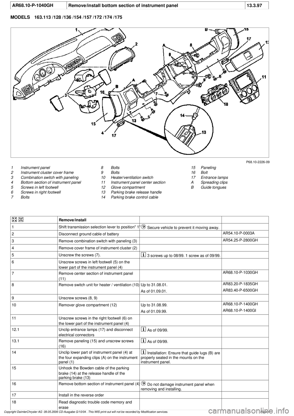
AR68.10-P-1040GH
Remove/install bottom section of instrument panel
13.3.97
MODELS
163.113 /128 /136 /154 /157 /172 /174 /175
P68.10-2226-09
1
Instrument panel
2
Instrument cluster cover frame
3
Combination switch with paneling
4
Bottom section of instrument panel
5
Screws in left footwell
6
Screws in right footwell
7
Bolts
15
Paneling
16
Bolt
17
Entrance lamps
A
Spreading clips
B
Guide tongues
8
Bolts
9
Bolts
10
Heater/ventilation switch
11
Instrument panel center section
12
Glove compartment
13
Parking brake release handle
14
Parking brake control cable
Remove/install
1
Shift transmission selection lever to position" 1"
Secure vehicle to prevent it moving away.
2
Disconnect ground cable of battery
AR54.10-P-0003A
3
Remove combination switch with paneling (3)
AR54.25-P-2800GH
4
Remove cover frame of instrument cluster (2)
5
Unscrew the screws (7).
3 screws up to 08/99. 1 screw as of 09/99.
6
Unscrew screws in left footwell (5) on the
lower part of the instrument panel (4)
7
Remove center section of instrument panel
(11)
AR68.10-P-1030GH
8
Remove switch unit for heater / ventilation (10)
Up to 31.08.01.
AR83.20-P-1835GH
As of 01.09.01.
AR83.40-P-6500GH
9
Unscrew screws (8, 9)
10
Remover glove compartment (12)
Up to 31.08.99.
AR68.10-P-1400GH
As of 01.09.99.
AR68.10-P-1400GI
11
Unscrew screws in the right footwell (6) on
the lower part of the instrument panel (4)
12.1
Unclip entrance lamps (17) and disconnect
electrical connectors
As of 09/99.
13.1
Remove paneling (15) and unscrew screws
(16)
As of 09/99.
14
Unclip lower part of instrument panel (4) at
the four expanding clips (A) on the instrument
panel (1)
Installation: Ensure that guide lugs (B) are
properly seated in the mounts on the
instrument panel.
15
Unhook the Bowden cable of the parking
brake (14) at the release handle of the
parking brake (13)
16
Remove bottom section of instrument panel (4)
Do not damage instrument panel when
removing and installing.
17
Install in the reverse order
18
Read diagnostic trouble code memory and
erase
Copyright DaimlerChrysler AG 09.05.2006 CD-Ausgabe G/10/04 . This WIS print-out will not be recorde
d by Modification services.
Page 1
Page 3523 of 4133
AUTOMATIC DIMMING INSIDE REARVIEW MIRROR, FUNCTION - GF68.49-P-0003GH
MODEL 163 as of 1.9.99 with CODE (249b) Automatic dimming inside rearview and outside rearview
mirror (driver)
Function requirements
No overvoltage or undervoltage
Term. 15R or 15 ON
Reverse gear not engaged
Interior lighting not switched on
Function
The glass of the inside rearview mirror (A67) can be electro-chromatically dimmed. The mirror glass between
the reflector and the glass cover contains a layer of electrolyte gel. The light transmission ratio of this gel
changes when a voltage is applied to it.
The light hitting the surface of the mirror is more or less reflected due to the variable of the actuation voltage.
The actuation voltage is controlled by the electronic circuitry in the inside rearview mirror. This is
accomplished depending on the ambient light and the light hitting the mirror.
The two input parameters are detected by the mirror dimming to rear sensor (A67h2) in the mirror housing
(rear) and by the mirror dimming forward sensor (A67h1) in the mirror glass of the inside rearview mirror
(A67).
The inside rearview mirror unit (A67) also acts as the master for the outside mirror dimming function
(driver's side).
CONTENTS - FUNCTION DESCRIPTION, AUTOMATIC DIMMING INSIDE REARVIEW MIRROR - GF68.49-P-0999GH
MODEL 163 as of 1.9.99 with CODE (249a) Automatic dimming inside rearview mirror
TROUBLE DIAGNOSIS
FRONT ASHTRAY DOES NOT OPEN SOFTLY OR IS STUCK - AF68.20-P-6000A
Garage door opener transmitter, location/ purpose GF68.05-P-1100A
Contents, function description of garage door opener GF68.05-P-0999A
Automatically dimming driver-side outside mirror, function GF88.79-P-2003GH
Function description, automatic dimming inside rearview mirror GF68.49-P-0003GH
Automatic dimming outside rearview mirror on driver's side, function GF88.79-P-2003GH
2001 Mercedes-Benz ML320
1998-2005 ACCESSORIES & BODY, CAB Interior Equipment - 163 Chassis
me
Saturday, October 02, 2010 3:35:21 PMPage 5 © 2006 Mitchell Repair Information Company, LLC.
Page 3538 of 4133
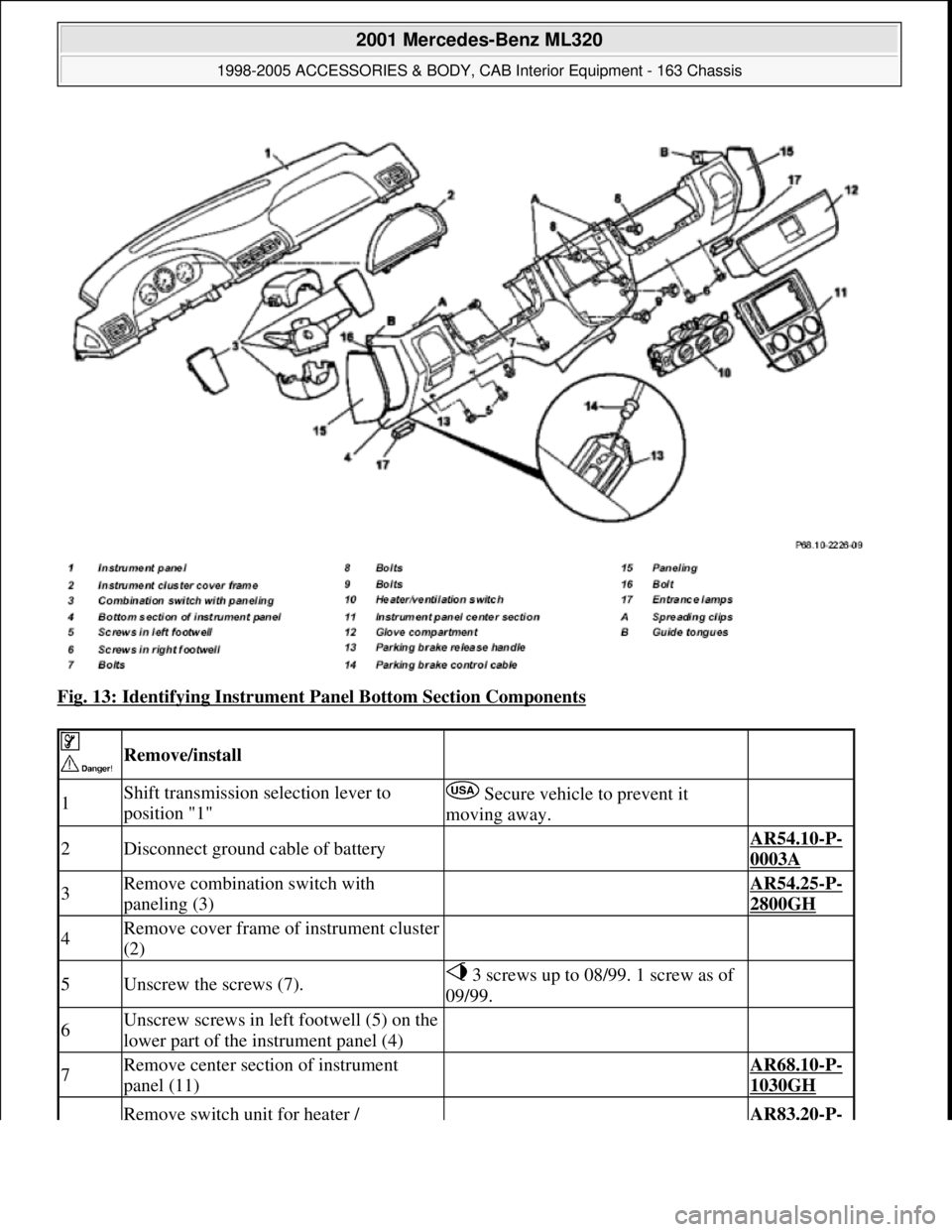
Fig. 13: Identifying Instrument Panel Bottom Section Components
Remove/install
1Shift transmission selection lever to
position "1" Secure vehicle to prevent it
moving away.
2Disconnect ground cable of battery AR54.10-P-
0003A
3Remove combination switch with
paneling (3) AR54.25-P-
2800GH
4Remove cover frame of instrument cluster
(2)
5Unscrew the screws (7). 3 screws up to 08/99. 1 screw as of
09/99.
6Unscrew screws in left footwell (5) on the
lower part of the instrument panel (4)
7Remove center section of instrument
panel (11) AR68.10-P-
1030GH
Remove switch unit for heater / AR83.20-P-
2001 Mercedes-Benz ML320
1998-2005 ACCESSORIES & BODY, CAB Interior Equipment - 163 Chassis
me
Saturday, October 02, 2010 3:35:21 PMPage 20 © 2006 Mitchell Repair Information Company, LLC.
Page 3562 of 4133
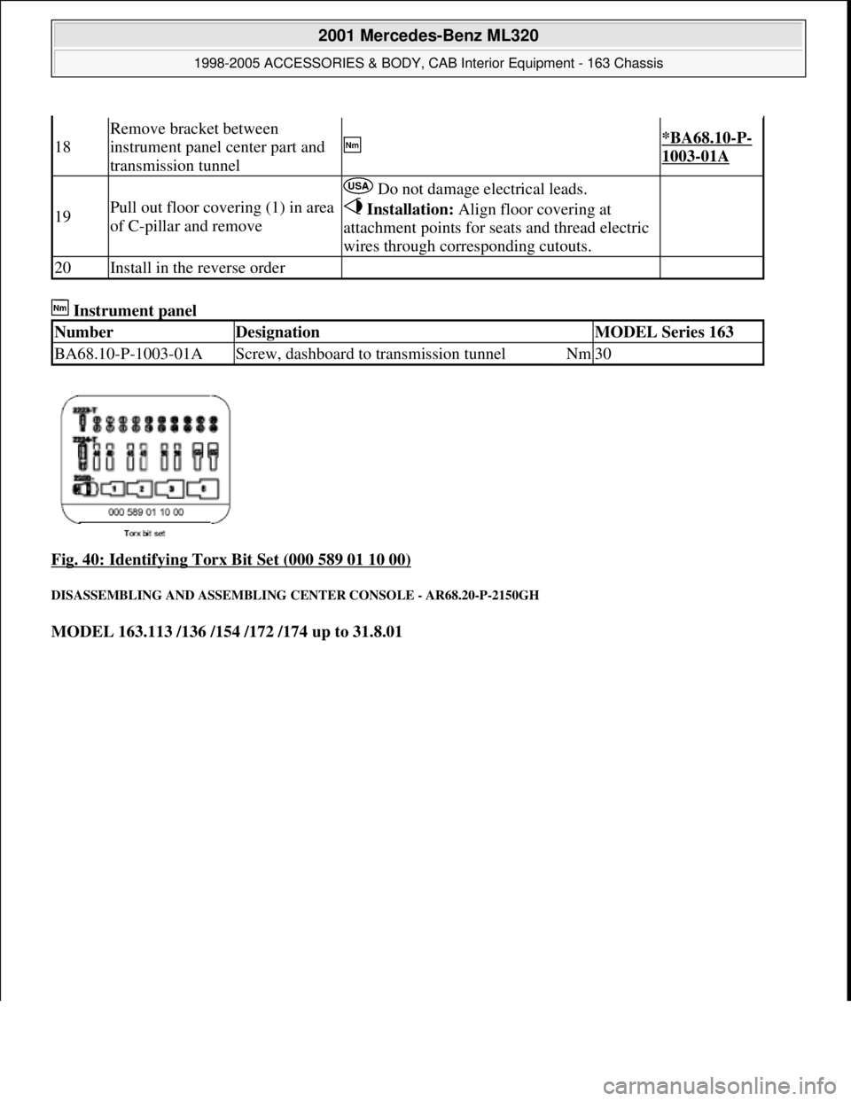
Instrument panel
Fig. 40: Identifying Torx Bit Set (000 589 01 10 00)
DISASSEMBLING AND ASSEMBLING CENTER CONSOLE - AR68.20-P-2150GH
MODEL 163.113 /136 /154 /172 /174 up to 31.8.01
18
Remove bracket between
instrument panel center part and
transmission tunnel
*BA68.10-P-
1003-01A
19Pull out floor covering (1) in area
of C-pillar and remove
Do not damage electrical leads.
Installation: Align floor covering at
attachment points for seats and thread electric
wires through corresponding cutouts.
20Install in the reverse order
NumberDesignationMODEL Series 163
BA68.10-P-1003-01AScrew, dashboard to transmission tunnelNm30
2001 Mercedes-Benz ML320
1998-2005 ACCESSORIES & BODY, CAB Interior Equipment - 163 Chassis
me
Saturday, October 02, 2010 3:35:22 PMPage 44 © 2006 Mitchell Repair Information Company, LLC.
Page 3606 of 4133

BT27.40-P-0003-01A
Magnet in oil pan, new part
TRANSMISSION
722.6## ## as of 2871384 as of 17.4.01,
722.7## ## as of 0153700 as of 9.7.01
P27.40-2027-01
To avoid malfunctions from metal particles, a magnet is placed in the oil pan.
The magnet can be retrofitted in the field.
Copyright DaimlerChrysler AG 28.05.2006 CD-Ausgabe G/10/04 . This WIS print-out will not be recorde
d by Modification services.
Page 1
Page 3715 of 4133
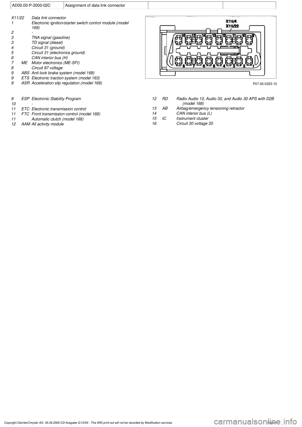
AD00.00-P-2000-02C
Assignment of data link connector
P07.00-0323-10
X11/22
Data link connector
1
Electronic ignition/starter switch control module (model
168)
2 -
3
TNA signal (gasoline)
3
TD signal (diesel)
4
Circuit 31 (ground)
5
Circuit 31 (electronics ground)
6
CAN interior bus (H)
7
ME
Motor electronics (ME-SFI)
8
Circuit 87 voltage
9
ABS
Anti-lock brake system (model 168)
9
ETS
Electronic traction system (model 163)
9
ASR
Acceleration slip regulation (model 168)
9
ESP
Electronic Stability Program
10
-
11 ETC
Electronic transmission control
11
FTC
Front transmission control (model 168)
11
Automatic clutch (model 168)
12
AAM
All activity module
12
RD
Radio Audio 10, Audio 30, and Audio 30 APS with D2B
(model 168)
13
AB
Airbag/emergency tensioning retractor
14
CAN interior bus (L)
15 IC
Instrument cluster
16
Circuit 30 voltage 30
Copyright DaimlerChrysler AG 05.06.2006 CD-Ausgabe G/10/04 . This WIS print-out will not be recorde
d by Modification services.
Page 1