Page 335 of 4133
285 Technical data
Te ch n ica l
data Instruments
and controlsOperation DrivingInstrument
cluster displayPractical hints Car care Index Identification labels
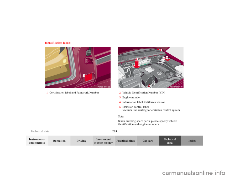
1Certification label and Paintwork Number2Vehicle Identification Number (VIN)
3Engine number
4Information label, California version
5Emission control label
Vacuum line routing for emission control system
Note:
When ordering spare parts, please specify vehicle
identification and engine numbers.
Page 752 of 4133
285
Technical data
Te ch n ica l
data
Instruments
and controls Operation Driving
Instrument
cluster display Practical hints Car care Index
Identification labels
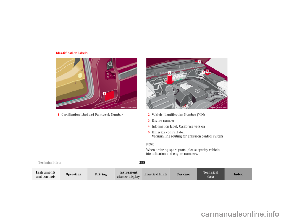
1 Certification label and Paintwork Number 2Vehicle Identification Number (VIN)
3 Engine number
4 Information label, California version
5 Emission control label
Vacuum line routing for emission control system
Note:
When ordering spare parts, please specify vehicle
identification and engine numbers.
Page 1096 of 4133
292 Technical dataIdentification labels
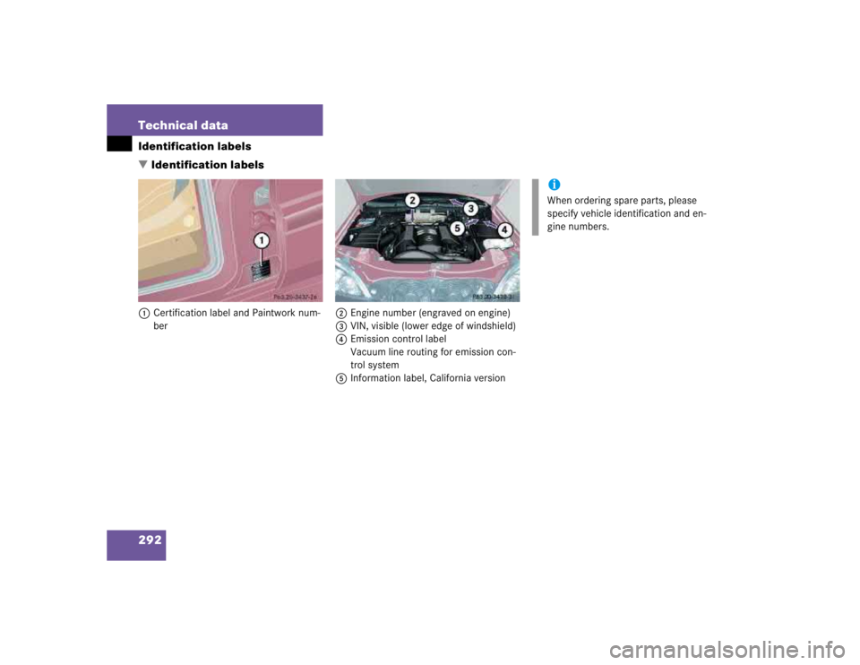
�Identification labels1Certification label and Paintwork num-
ber2Engine number (engraved on engine)
3VIN, visible (lower edge of windshield)
4Emission control label
Vacuum line routing for emission con-
trol system
5Information label, California version
iWhen ordering spare parts, please
specify vehicle identification and en-
gine numbers.
Page 1155 of 4133
interconnected flap shafts are closed by means of vacuum by the intake manifold switchover diaphragm unit.
When the variable intake manifold switchover valve is open, the vacuum is supplied from a vacuum reservoir
with check valve in the intake manifold. The reservoir volume is designed for about 5 operations without
renewed evacuation.
The variable flaps open by means of spring force.
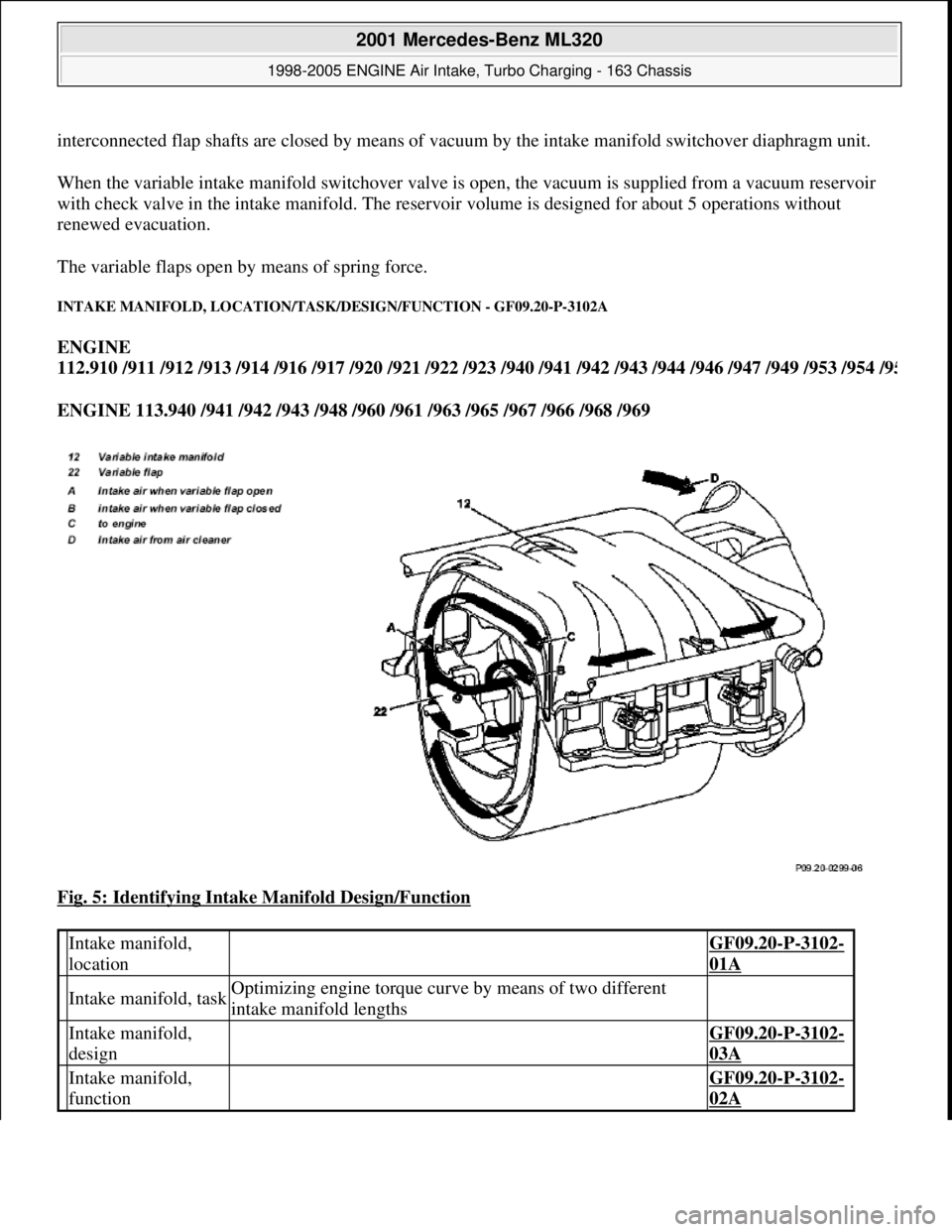
INTAKE MANIFOLD, LOCATION/TASK/DESIGN/FUNCTION - GF09.20-P-3102A
ENGINE
112.910 /911 /912 /913 /914 /916 /917 /920 /921 /922 /923 /940 /941 /942 /943 /944 /946 /947 /949 /953 /954 /9
5
ENGINE 113.940 /941 /942 /943 /948 /960 /961 /963 /965 /967 /966 /968 /969
Fig. 5: Identifying Intake Manifold Design/Function
Intake manifold,
location GF09.20-P-3102-
01A
Intake manifold, taskOptimizing engine torque curve by means of two different
intake manifold lengths
Intake manifold,
design GF09.20-P-3102-
03A
Intake manifold,
function GF09.20-P-3102-
02A
2001 Mercedes-Benz ML320
1998-2005 ENGINE Air Intake, Turbo Charging - 163 Chassis
me
Saturday, October 02, 2010 3:16:57 PMPage 4 © 2006 Mitchell Repair Information Company, LLC.
Page 1163 of 4133
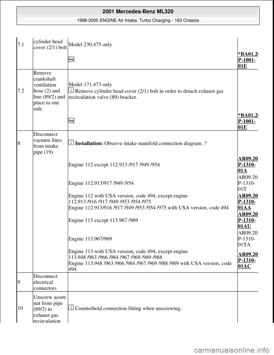
7.1cylinder head
cover (2/1) boltModel 230.475 only
*BA01.20
P-1001-
01E
7.2
Remove
crankshaft
ventilation
hose (2) and
line (89/2) and
place to one
side
Model 171.473 only
Remove cylinder head cover (2/1) bolt in order to detach exhaust gas
recirculation valve (89) bracket.
*BA01.20
P-1001-
01E
8
Disconnect
vacuum lines
from intake
pipe (19)
Installation: Observe intake manifold connection diagram. ?
Engine 112 except 112.913 /917 /949 /954AR09.20
-
P-1310-
01A
Engine 112.913/917 /949 /954AR09.20
-
P-1310-
01T
Engine 112 with USA version, code 494, except engine
112.913 /916 /917 /949 /953 /954 /975
Engine 112.913/916 /917 /949 /953 /954 /975 with USA version, code 494AR09.20-
P-1310-
01AA
Engine 113 except 113.967 /969AR09.20
-
P-1310-
01AU
Engine 113.967/969AR09.20
-
P-1310-
01TA
Engine 113 with USA version, code 494, except engine
113.948 /963 /966 /984 /967 /969 /989 /988
Engine 113.948 /963 /966 /984 /967 /969 /988 /989 with USA version, code
494AR09.20-
P-1310-
01AC
9
Disconnect
electrical
connectors
10
Unscrew acorn
nut from pipe
(89/2) to
exhaust gas
recirculation
Counterhold connection fitting when unscrewing.
2001 Mercedes-Benz ML320
1998-2005 ENGINE Air Intake, Turbo Charging - 163 Chassis
me
Saturday, October 02, 2010 3:16:57 PMPage 12 © 2006 Mitchell Repair Information Company, LLC.
Page 2133 of 4133
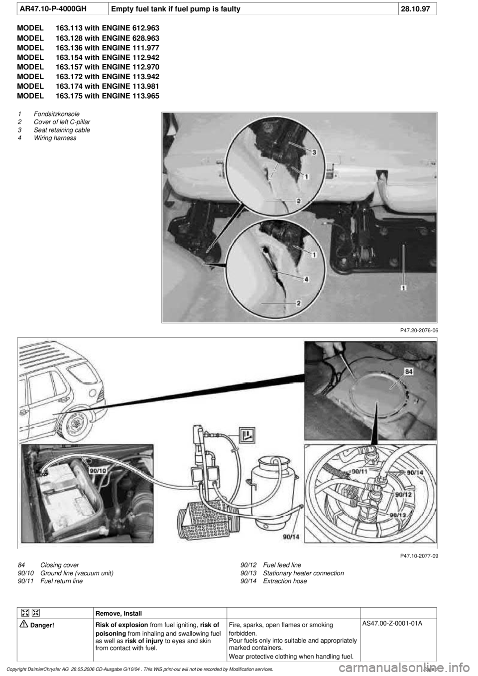
AR47.10-P-4000GH
Empty fuel tank if fuel pump is faulty
28.10.97
MODEL
163.113 with ENGINE 612.963
MODEL
163.128 with ENGINE 628.963
MODEL
163.136 with ENGINE 111.977
MODEL
163.154 with ENGINE 112.942
MODEL
163.157 with ENGINE 112.970
MODEL
163.172 with ENGINE 113.942
MODEL
163.174 with ENGINE 113.981
MODEL
163.175 with ENGINE 113.965
P47.20-2076-06
1
Fondsitzkonsole
2
Cover of left C-pillar
3
Seat retaining cable
4
Wiring harness
P47.10-2077-09
84
Closing cover
90/10
Ground line (vacuum unit)
90/11
Fuel return line
90/12
Fuel feed line
90/13
Stationary heater connection
90/14
Extraction hose
Remove, Install
Danger!
Risk of explosion
from fuel igniting,
risk of
poisoning
from inhaling and swallowing fuel
as well as
risk of injury
to eyes and skin
from contact with fuel.
Fire, sparks, open flames or smoking
forbidden.
Pour fuels only into suitable and appropriately
marked containers.
Wear protective clothing when handling fuel.
AS47.00-Z-0001-01A
Copyright DaimlerChrysler AG 28.05.2006 CD-Ausgabe G/10/04 . This WIS print-out will not be recorde
d by Modification services.
Page 1
Page 2141 of 4133
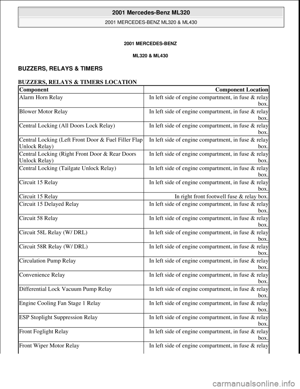
2001 MERCEDES-BENZ
ML320 & ML430
BUZZERS, RELAYS & TIMERS
BUZZERS, RELAYS & TIMERS LOCATION
ComponentComponent Location
Alarm Horn RelayIn left side of engine compartment, in fuse & relay
box.
Blower Motor RelayIn left side of engine compartment, in fuse & relay
box.
Central Locking (All Doors Lock Relay)In left side of engine compartment, in fuse & relay
box.
Central Locking (Left Front Door & Fuel Filler Flap
Unlock Relay)In left side of engine compartment, in fuse & relay
box.
Central Locking (Right Front Door & Rear Doors
Unlock Relay)In left side of engine compartment, in fuse & relay
box.
Central Locking (Tailgate Unlock Relay)In left side of engine compartment, in fuse & relay
box.
Circuit 15 RelayIn left side of engine compartment, in fuse & relay
box.
Circuit 15 RelayIn right front footwell fuse & relay box.
Circuit 15 Delayed RelayIn left side of engine compartment, in fuse & relay
box.
Circuit 58 RelayIn left side of engine compartment, in fuse & relay
box.
Circuit 58L Relay (W/ DRL)In left side of engine compartment, in fuse & relay
box.
Circuit 58R Relay (W/ DRL)In left side of engine compartment, in fuse & relay
box.
Circulation Pump RelayIn left side of engine compartment, in fuse & relay
box.
Convenience RelayIn left side of engine compartment, in fuse & relay
box.
Differential Lock Vacuum Pump RelayIn left side of engine compartment, in fuse & relay
box.
Engine Cooling Fan Stage 1 RelayIn left side of engine compartment, in fuse & relay
box.
ESP Stoplight Suppression RelayIn left side of engine compartment, in fuse & relay
box.
Front Foglight RelayIn left side of engine compartment, in fuse & relay
box.
Front Wiper Motor RelayIn left side of engine compartment, in fuse & relay
2001 Mercedes-Benz ML320
2001 MERCEDES-BENZ ML320 & ML430
2001 Mercedes-Benz ML320
2001 MERCEDES-BENZ ML320 & ML430
me
Saturday, October 02, 2010 3:21:17 PMPage 1 © 2006 Mitchell Repair Information Company, LLC.
me
Saturday, October 02, 2010 3:21:20 PMPage 1 © 2006 Mitchell Repair Information Company, LLC.
Page 2143 of 4133
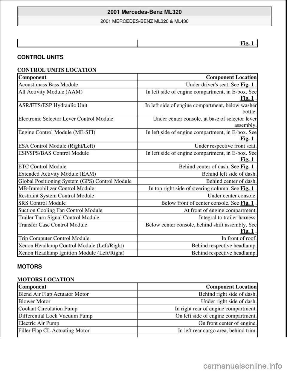
CONTROL UNITS
CONTROL UNITS LOCATION
MOTORS
MOTORS LOCATION
Fig. 1 .
ComponentComponent Location
Acoustimass Bass ModuleUnder driver's seat. See Fig. 1 .
All Activity Module (AAM)In left side of engine compartment, in E-box. See
Fig. 1
.
ASR/ETS/ESP Hydraulic UnitIn left side of engine compartment, below washer
bottle.
Electronic Selector Lever Control ModuleUnder center console, at base of selector lever
assembly.
Engine Control Module (ME-SFI)In left side of engine compartment, in E-box. See
Fig. 1
.
ESA Control Module (Right/Left)Under respective front seat.
ESP/SPS/BAS Control ModuleIn left side of engine compartment, in E-box. See
Fig. 1
.
ETC Control ModuleBehind center of dash. See Fig. 1 .
Extended Activity Module (EAM)Behind left side of dash.
Global Positioning System (GPS) Control ModuleBehind center of dash.
MB-Immobilizer Control ModuleIn top right side of steering column. See Fig. 1 .
Restraint System Control ModuleUnder center console.
SRS Control ModuleBelow front of center console. See Fig. 1 .
Suction Cooling Fan Control ModuleAt front of engine compartment.
Trailer Turn Signal Control ModuleIntegral to trailer harness.
Transfer Case Control ModuleBelow center console, behind shift assembly. See
Fig. 1
.
Trip Computer Control ModuleIn front of roof.
Xenon Headlamp Control Module (Left/Right)Behind respective headlamp.
Xenon Headlamp Ignition Module (Left/Right)Behind respective headlamp.
ComponentComponent Location
Blend Air Flap Actuator MotorBehind right side of dash.
Blower MotorUnder right side of dash.
Coolant Circulation PumpIn right rear of engine compartment.
Differential Lock Vacuum PumpOn left side of engine compartment.
Electric Air PumpOn front center of engine.
Filler Flap CL Actuating MotorIn left rear cargo area, behind trim.
2001 Mercedes-Benz ML320
2001 MERCEDES-BENZ ML320 & ML430
me
Saturday, October 02, 2010 3:21:17 PMPage 3 © 2006 Mitchell Repair Information Company, LLC.