Page 1489 of 4133
AR54.10-P-0005GH
Remove/install battery
23.3.00
MODEL
163.113 /128 /136 /154 /157 /172 /174 /175
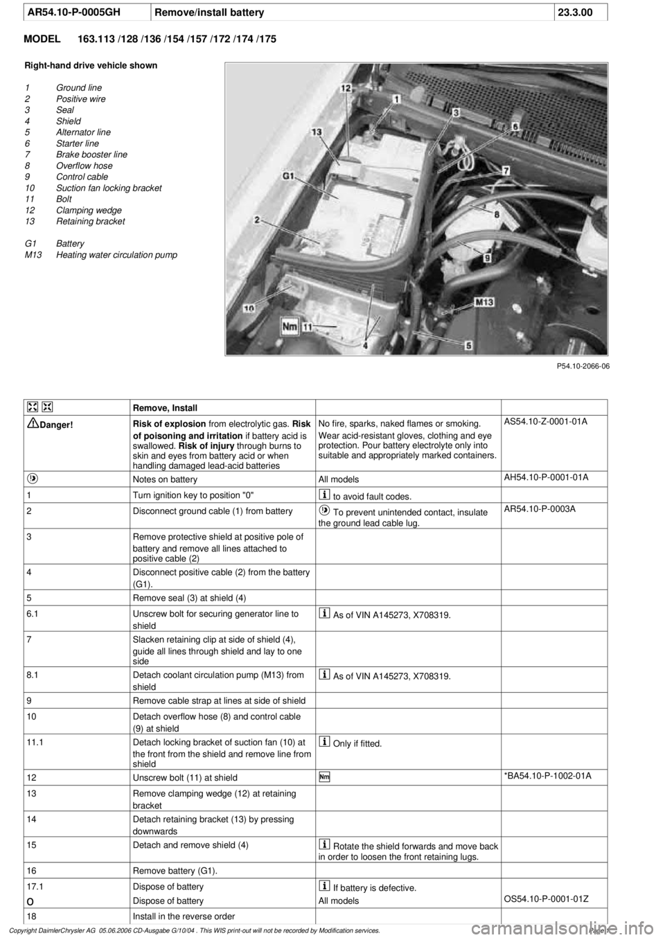
P54.10-2066-06
Right-hand drive vehicle shown
1
Ground line
2
Positive wire
3
Seal
4
Shield
5
Alternator line
6
Starter line
7
Brake booster line
8
Overflow hose
9
Control cable
10
Suction fan locking bracket
11
Bolt
12
Clamping wedge
13
Retaining bracket
G1 Battery
M13
Heating water circulation pump
Remove, Install
Danger!
Risk of explosion
from electrolytic gas.
Risk
of poisoning and irritation
if battery acid is
swallowed.
Risk of injury
through burns to
skin and eyes from battery acid or when
handling damaged lead-acid batteries
No fire, sparks, naked flames or smoking.
Wear acid-resistant gloves, clothing and eye
protection. Pour battery electrolyte only into
suitable and appropriately marked containers.
AS54.10-Z-0001-01A
Notes on battery
All models
AH54.10-P-0001-01A
1
Turn ignition key to position "0"
to avoid fault codes.
2
Disconnect ground cable (1) from battery
To prevent unintended contact, insulate
the ground lead cable lug.
AR54.10-P-0003A
3
Remove protective shield at positive pole of
battery and remove all lines attached to
positive cable (2)
4
Disconnect positive cable (2) from the battery
(G1).
5
Remove seal (3) at shield (4)
6.1
Unscrew bolt for securing generator line to
shield
As of VIN A145273, X708319.
7
Slacken retaining clip at side of shield (4),
guide all lines through shield and lay to one
side
8.1
Detach coolant circulation pump (M13) from
shield
As of VIN A145273, X708319.
9
Remove cable strap at lines at side of shield
10
Detach overflow hose (8) and control cable
(9) at shield
11.1
Detach locking bracket of suction fan (10) at
the front from the shield and remove line from
shield
Only if fitted.
12
Unscrew bolt (11) at shield
*BA54.10-P-1002-01A
13
Remove clamping wedge (12) at retaining
bracket
14
Detach retaining bracket (13) by pressing
downwards
15
Detach and remove shield (4)
Rotate the shield forwards and move back
in order to loosen the front retaining lugs.
16
Remove battery (G1).
17.1
Dispose of battery
If battery is defective.
o
Dispose of battery
All models
OS54.10-P-0001-01Z
18
Install in the reverse order
Copyright DaimlerChrysler AG 05.06.2006 CD-Ausgabe G/10/04 . This WIS print-out will not be recorde
d by Modification services.
Page 1
Page 1799 of 4133
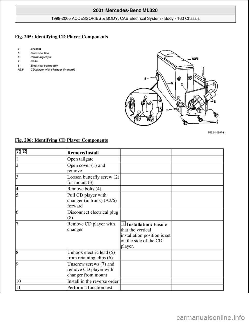
Fig. 205: Identifying CD Player Components
Fig. 206: Identifying CD Player Components
Remove/Install
1Open tailgate
2Open cover (1) and
remove
3Loosen butterfly screw (2)
for mount (3)
4Remove bolts (4).
5Pull CD player with
changer (in trunk) (A2/6)
forward
6Disconnect electrical plug
(8)
7Remove CD player with
changer Installation: Ensure
that the vertical
installation position is set
on the side of the CD
player.
8Unhook electric lead (5)
from retaining clips (6)
9Unscrew screws (7) and
remove CD player with
changer from mount
10Install in the reverse order
11Perform a function test
2001 Mercedes-Benz ML320
1998-2005 ACCESSORIES & BODY, CAB Electrical System - Body - 163 Chassis
me
Saturday, October 02, 2010 3:30:10 PMPage 304 © 2006 Mitchell Repair Information Company, LLC.
Page 1878 of 4133
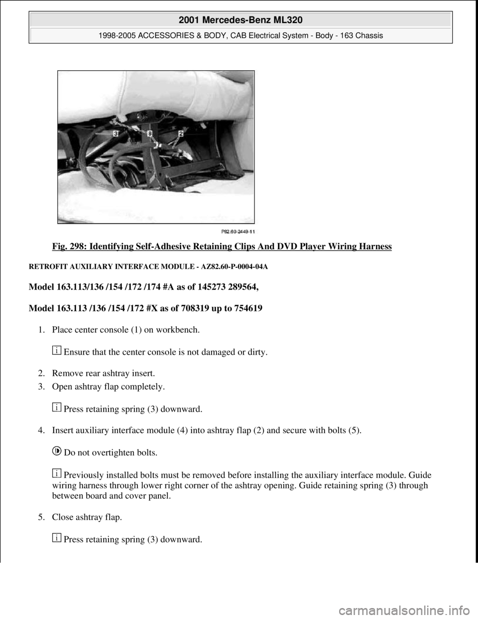
Fig. 298: Identifying Self-Adhesive Retaining Clips And DVD Player Wiring Harness
RETROFIT AUXILIARY INTERFACE MODULE - AZ82.60-P-0004-04A
Model 163.113/136 /154 /172 /174 #A as of 145273 289564,
Model 163.113 /136 /154 /172 #X as of 708319 up to 754619
1. Place center console (1) on workbench.
Ensure that the center console is not damaged or dirty.
2. Remove rear ashtray insert.
3. Open ashtray flap completely.
Press retaining spring (3) downward.
4. Insert auxiliary interface module (4) into ashtray flap (2) and secure with bolts (5).
Do not overtighten bolts.
Previously installed bolts must be removed before installing the auxiliary interface module. Guide
wiring harness through lower right corner of the ashtray opening. Guide retaining spring (3) through
between board and cover panel.
5. Close ashtray flap.
Press retainin
g spring (3) downward.
2001 Mercedes-Benz ML320
1998-2005 ACCESSORIES & BODY, CAB Electrical System - Body - 163 Chassis
me
Saturday, October 02, 2010 3:30:12 PMPage 383 © 2006 Mitchell Repair Information Company, LLC.
Page 1879 of 4133
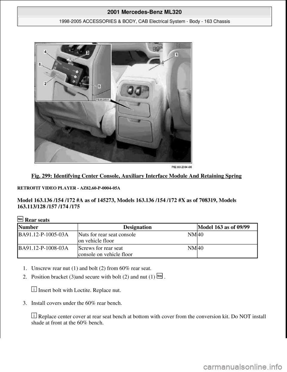
Fig. 299: Identifying Center Console, Auxiliary Interface Module And Retaining Spring
RETROFIT VIDEO PLAYER - AZ82.60-P-0004-05A
Model 163.136 /154 /172 #A as of 145273, Models 163.136 /154 /172 #X as of 708319, Models
163.113/128 /157 /174 /175
Rear seats
1. Unscrew rear nut (1) and bolt (2) from 60% rear seat.
2. Position bracket (3)and secure with bolt (2) and nut (1) .
Insert bolt with Loctite. Replace nut.
3. Install covers under the 60% rear bench.
Replace center cover at rear seat bench at bottom with cover from the conversion kit. Do NOT install
shade at front at the 60% bench.
NumberDesignationModel 163 as of 09/99
BA91.12-P-1005-03ANuts for rear seat console
on vehicle floorNM40
BA91.12-P-1008-03AScrews for rear seat
console on vehicle floorNM40
2001 Mercedes-Benz ML320
1998-2005 ACCESSORIES & BODY, CAB Electrical System - Body - 163 Chassis
me
Saturday, October 02, 2010 3:30:12 PMPage 384 © 2006 Mitchell Repair Information Company, LLC.
Page 2016 of 4133
AR68.20-P-2210GH
Remove/install rear center console switch module
25.5.01
MODEL
163.113 /154 /174 #A as of 289565,
163.113 #X as of 754620,
163.128 /157 /175
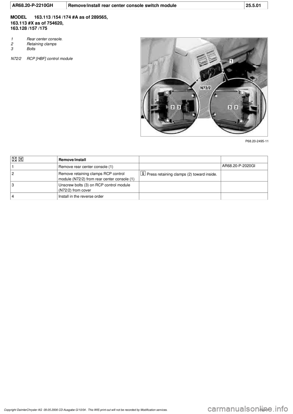
P68.20-2495-11
1
Rear center console.
2
Retaining clamps
3
Bolts
N72/2
RCP [HBF] control module
Remove/install
1
Remove rear center console (1)
AR68.20-P-2020GI
2
Remove retaining clamps RCP control
module (N72/2) from rear center console (1)
Press retaining clamps (2) toward inside.
3
Unscrew bolts (3) on RCP control module
(N72/2) from cover
4
Install in the reverse order
Copyright DaimlerChrysler AG 09.05.2006 CD-Ausgabe G/10/04 . This WIS print-out will not be recorde
d by Modification services.
Page 1
Page 2024 of 4133
AR68.20-P-2370GH
Remove/install armrest lid on center console
15.4.97
MODEL
163.113 /128 /136 /154 /157 /172 /174 /175
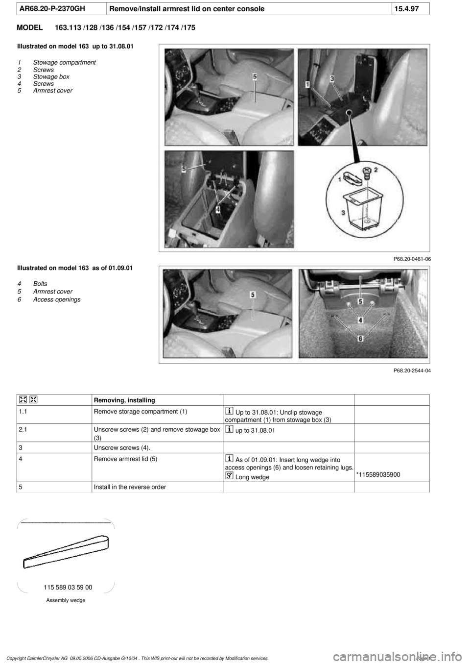
P68.20-0461-06
Illustrated on model 163 up to 31.08.01
1
Stowage compartment
2
Screws
3
Stowage box
4
Screws
5
Armrest cover
P68.20-2544-04
Illustrated on model 163 as of 01.09.01
4
Bolts
5
Armrest cover
6
Access openings
Removing, installing
1.1
Remove storage compartment (1)
Up to 31.08.01: Unclip stowage
compartment (1) from stowage box (3)
2.1
Unscrew screws (2) and remove stowage box
(3)
up to 31.08.01
3
Unscrew screws (4).
4
Remove armrest lid (5)
As of 01.09.01: Insert long wedge into
access openings (6) and loosen retaining lugs.
Long wedge
*115589035900
5
Install in the reverse order
Assembly wedge
115 589 03 59 00
Copyright DaimlerChrysler AG 09.05.2006 CD-Ausgabe G/10/04 . This WIS print-out will not be recorde
d by Modification services.
Page 1
Page 2057 of 4133
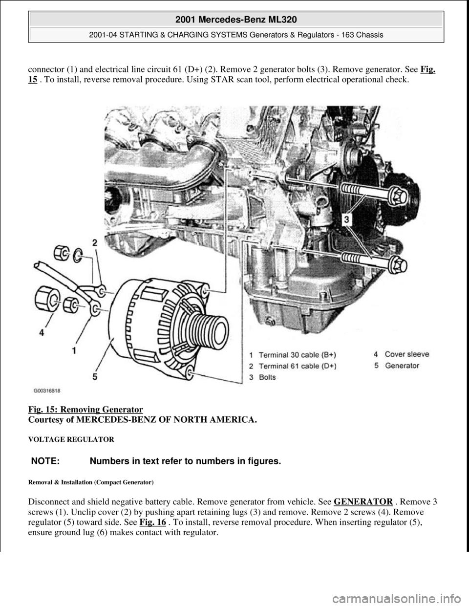
connector (1) and electrical line circuit 61 (D+) (2). Remove 2 generator bolts (3). Remove generator. See Fig.
15 . To install, reverse removal procedure. Using STAR scan tool, perform electrical operational check.
Fig. 15: Removing Generator
Courtesy of MERCEDES-BENZ OF NORTH AMERICA.
VOLTAGE REGULATOR
Removal & Installation (Compact Generator)
Disconnect and shield negative battery cable. Remove generator from vehicle. See GENERATOR . Remove 3
screws (1). Unclip cover (2) by pushing apart retaining lugs (3) and remove. Remove 2 screws (4). Remove
regulator (5) toward side. See Fig. 16
. To install, reverse removal procedure. When inserting regulator (5),
ensure
ground lug (6) makes contact with regulator.
NOTE: Numbers in text refer to numbers in figures.
2001 Mercedes-Benz ML320
2001-04 STARTING & CHARGING SYSTEMS Generators & Regulators - 163 Chassis
me
Saturday, October 02, 2010 3:20:32 PMPage 23 © 2006 Mitchell Repair Information Company, LLC.
Page 2110 of 4133
AR72.10-P-2100GH
Remove/install door catch
11.2.97
MODEL
163.113 /128 /136 /154 /157 /172 /174 /175
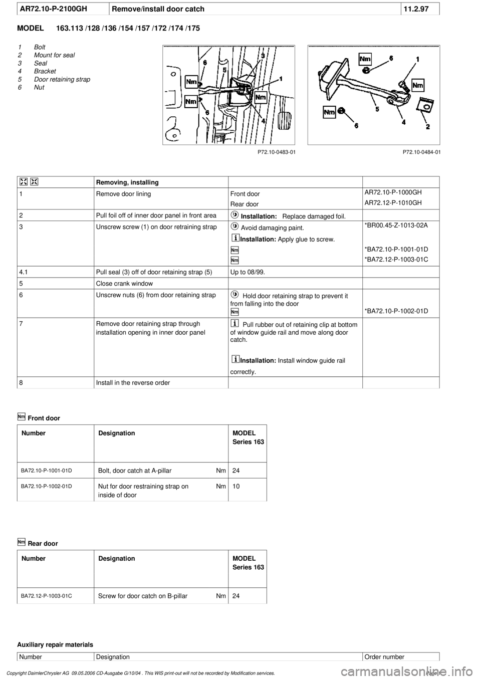
P72.10-0483-01
1
Bolt
2
Mount for seal
3
Seal
4
Bracket
5
Door retaining strap
6
Nut
P72.10-0484-01
Removing, installing
1
Remove door lining
Front door
AR72.10-P-1000GH
Rear door
AR72.12-P-1010GH
2
Pull foil off of inner door panel in front area
Installation:
Replace damaged foil.
3
Unscrew screw (1) on door retraining strap
Avoid damaging paint.
Installation:
Apply glue to screw.
*BR00.45-Z-1013-02A
*BA72.10-P-1001-01D
*BA72.12-P-1003-01C
4.1
Pull seal (3) off of door retaining strap (5)
Up to 08/99.
5
Close crank window
6
Unscrew nuts (6) from door retaining strap
Hold door retaining strap to prevent it
from falling into the door
*BA72.10-P-1002-01D
7
Remove door retaining strap through
installation opening in inner door panel
Pull rubber out of retaining clip at bottom
of window guide rail and move along door
catch.
Installation:
Install window guide rail
correctly.
8
Install in the reverse order
Front door
Number
Designation
MODEL
Series 163
BA72.10-P-1001-01DBolt, door catch at A-pillar
Nm
24
BA72.10-P-1002-01D
Nut for door restraining strap on
inside of door
Nm
10
Rear door
Number
Designation
MODEL
Series 163
BA72.12-P-1003-01C
Screw for door catch on B-pillar
Nm
24
Auxiliary repair materials
Number
Designation
Order number
Copyright DaimlerChrysler AG 09.05.2006 CD-Ausgabe G/10/04 . This WIS print-out will not be recorde
d by Modification services.
Page 1