1997 MERCEDES-BENZ ML320 timing
[x] Cancel search: timingPage 322 of 4133
272 Emergency operation of sliding/pop-up roof
Te ch n ica l
data Instruments
and controlsOperation DrivingInstrument
cluster displayPractical hintsCar care Index
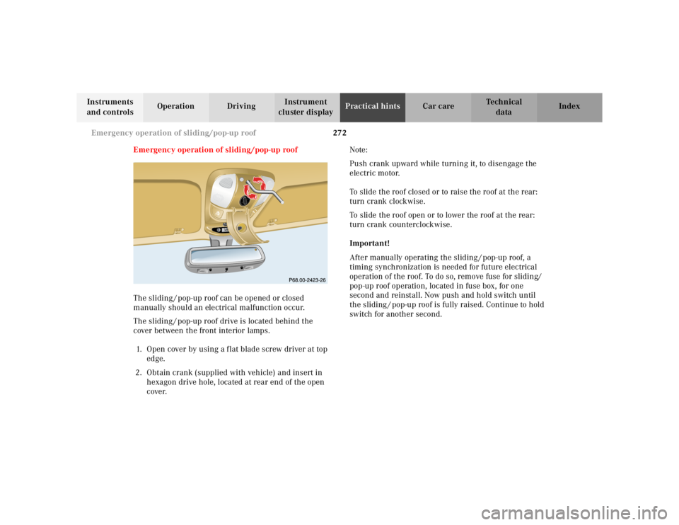
Emergency operation of sliding/pop-up roof
The sliding / pop-up roof can be opened or closed
manually should an electrical malfunction occur.
The sliding / pop-up roof drive is located behind the
cover between the front interior lamps.
1. Open cover by using a f lat blade screw driver at top
edge.
2. Obtain crank (supplied with vehicle) and insert in
hexagon drive hole, located at rear end of the open
cover.Note:
Push crank upward while turning it, to disengage the
electric motor.
To slide the roof closed or to raise the roof at the rear:
turn crank clockwise.
To slide the roof open or to lower the roof at the rear:
turn crank counterclockwise.
Important!
After manually operating the sliding / pop-up roof, a
timing synchronization is needed for future electrical
operation of the roof. To do so, remove fuse for sliding/
pop-up roof operation, located in fuse box, for one
second and reinstall. Now push and hold switch until
the sliding / pop-up roof is fully raised. Continue to hold
switch for another second.
RESETMODEMODE
Page 324 of 4133
274 Manual release for fuel filler flap
Te ch n ica l
data Instruments
and controlsOperation DrivingInstrument
cluster displayPractical hintsCar care Index
Important!
After manually operating the Skyview Top, a timing
synchronization is needed for future electrical operation
o f the Sk yv iew To p. To do s o, tur n key i n stee ri n g lock to
position 2. Now push and hold switch until the Skyview
Top is fully closed. Continue to hold switch for
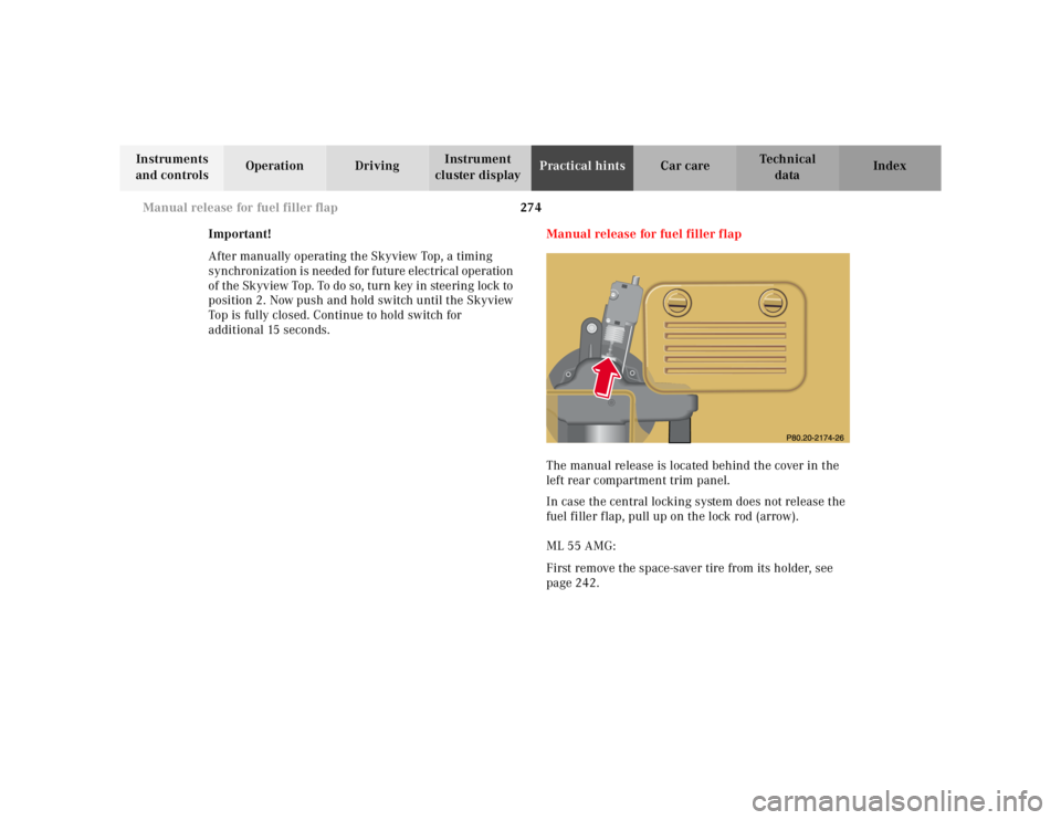
additional 15 seconds.Manual release for fuel filler flap
The manual release is located behind the cover in the
left rear compartment trim panel.
In case the central locking system does not release the
fuel filler flap, pull up on the lock rod (arrow).
ML 55 AMG:
First remove the space-saver tire from its holder, see
page 242.
Page 739 of 4133
272
Emergency operation of sliding/pop-up roof
Te ch n ica l
data
Instruments
and controls Operation Driving
Instrument
cluster display Practical hints
Car care Index
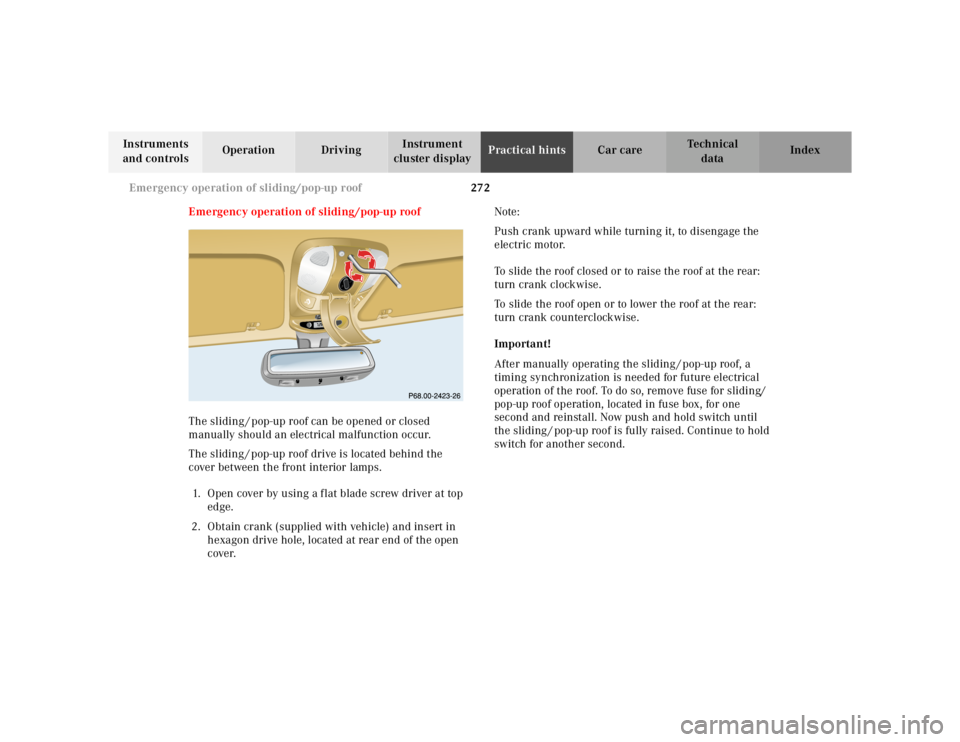
Emergency operation of sliding/pop-up roof
The sliding / pop-up roof can be opened or closed
manually should an electrical malfunction occur.
The sliding / pop-up roof drive is located behind the
cover between the front interior lamps.
1. Open cover by using a f lat blade screw driver at top edge.
2. Obtain crank (supplied with vehicle) and insert in hexagon drive hole, located at rear end of the open
cover. Note:
Push crank upward while turning it, to disengage the
electric motor.
To slide the roof closed or to raise the roof at the rear:
turn crank clockwise.
To slide the roof open or to lower the roof at the rear:
turn crank counterclockwise.
Important!
After manually operating the sliding / pop-up roof, a
timing synchronization is needed for future electrical
operation of the roof. To do so, remove fuse for sliding/
pop-up roof operation, located in fuse box, for one
second and reinstall. Now push and hold switch until
the sliding / pop-up roof is fully raised. Continue to hold
switch for another second.
R ESETM O
DEM OD
E
Page 741 of 4133
274
Manual release for fuel filler flap
Te ch n ica l
data
Instruments
and controls Operation Driving
Instrument
cluster display Practical hints
Car care Index
Important!
After manually operating the Skyview Top, a timing
synchronization is needed for future electrical operation
o f the Sk yv iew To p. To do s o, tur n key i n stee ri n g lock to
position 2. Now push and hold switch until the Skyview
Top is fully closed. Continue to hold switch for
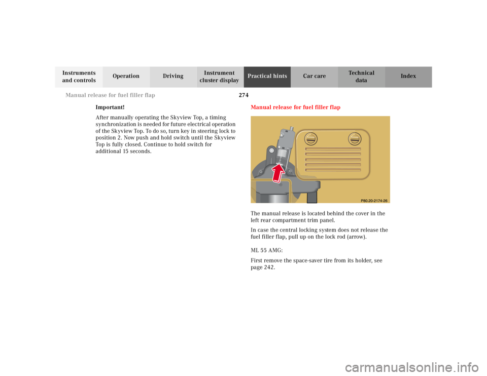
additional 15 seconds. Manual release for fuel filler flap
The manual release is located behind the cover in the
left rear compartment trim panel.
In case the central locking system does not release the
fuel filler flap, pull up on the lock rod (arrow).
ML 55 AMG:
First remove the space-saver tire from its holder, see
page 242.
Page 1507 of 4133
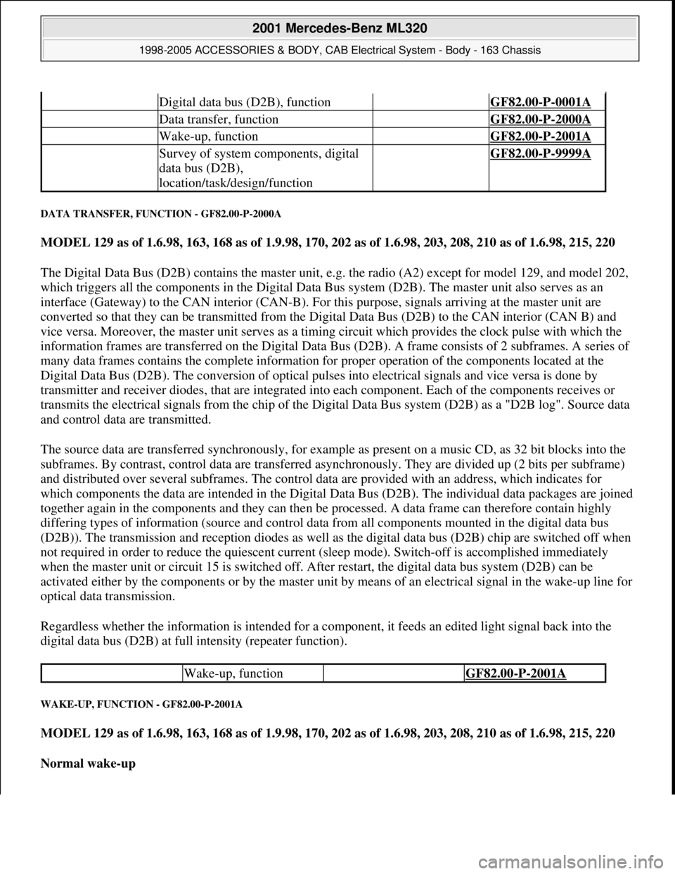
DATA TRANSFER, FUNCTION - GF82.00-P-2000A
MODEL 129 as of 1.6.98, 163, 168 as of 1.9.98, 170, 202 as of 1.6.98, 203, 208, 210 as of 1.6.98, 215, 220
The Digital Data Bus (D2B) contains the master unit, e.g. the radio (A2) except for model 129, and model 202,
which triggers all the components in the Digital Data Bus system (D2B). The master unit also serves as an
interface (Gateway) to the CAN interior (CAN-B). For this purpose, signals arriving at the master unit are
converted so that they can be transmitted from the Digital Data Bus (D2B) to the CAN interior (CAN B) and
vice versa. Moreover, the master unit serves as a timing circuit which provides the clock pulse with which the
information frames are transferred on the Digital Data Bus (D2B). A frame consists of 2 subframes. A series of
many data frames contains the complete information for proper operation of the components located at the
Digital Data Bus (D2B). The conversion of optical pulses into electrical signals and vice versa is done by
transmitter and receiver diodes, that are integrated into each component. Each of the components receives or
transmits the electrical signals from the chip of the Digital Data Bus system (D2B) as a "D2B log". Source data
and control data are transmitted.
The source data are transferred synchronously, for example as present on a music CD, as 32 bit blocks into the
subframes. By contrast, control data are transferred asynchronously. They are divided up (2 bits per subframe)
and distributed over several subframes. The control data are provided with an address, which indicates for
which components the data are intended in the Digital Data Bus (D2B). The individual data packages are joined
together again in the components and they can then be processed. A data frame can therefore contain highly
differing types of information (source and control data from all components mounted in the digital data bus
(D2B)). The transmission and reception diodes as well as the digital data bus (D2B) chip are switched off when
not required in order to reduce the quiescent current (sleep mode). Switch-off is accomplished immediately
when the master unit or circuit 15 is switched off. After restart, the digital data bus system (D2B) can be
activated either by the components or by the master unit by means of an electrical signal in the wake-up line for
optical data transmission.
Regardless whether the information is intended for a component, it feeds an edited light signal back into the
digital data bus (D2B) at full intensity (repeater function).
WAKE-UP, FUNCTION - GF82.00-P-2001A
MODEL 129 as of 1.6.98, 163, 168 as of 1.9.98, 170, 202 as of 1.6.98, 203, 208, 210 as of 1.6.98, 215, 220
Normal wake-up
Digital data bus (D2B), function GF82.00-P-0001A
Data transfer, function GF82.00-P-2000A
Wake-up, function GF82.00-P-2001A
Survey of system components, digital
data bus (D2B),
location/task/design/function GF82.00-P-9999A
Wake-up, function GF82.00-P-2001A
2001 Mercedes-Benz ML320
1998-2005 ACCESSORIES & BODY, CAB Electrical System - Body - 163 Chassis
me
Saturday, October 02, 2010 3:30:04 PMPage 12 © 2006 Mitchell Repair Information Company, LLC.
Page 1705 of 4133
RADIO RECEPTION, TESTING ELECTRICAL SYSTEM, RADIO (RD) - AD82.60-P-6000-07A
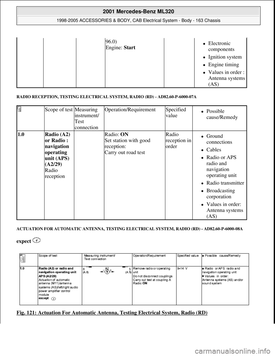
ACTUATION FOR AUTO MATIC ANTENNA, TESTING E LECTRICAL SYSTEM, RADIO (RD) - AD82.60-P-6000-08A
expect
Fig. 121: Actuation For Automatic Antenn a, Testing Electrical System, Radio (RD)
96.0)
Engine: Start Electronic
components
Ignition system
Engine timing
Values in order :
Antenna systems
(AS)
Scope of testMeasuring
instrument/
Test
connectionOperation/RequirementSpecified
valuePossible
cause/Remedy
1.0 Radio (A2)
or Radio :
navigation
operating
unit (APS)
(A2/29)
Radio
reception Radio: ON
Set station with good
reception:
Carry out road testRadio
reception in
orderGround
connections
Cables
Radio or APS
radio and
navigation
operating unit
Radio transmitter
Broadcasting
corporation
Values in order:
Antenna systems
(AS)
2001 Mercedes-Benz ML320
1998-2005 ACCESSORIES & BODY, CAB Electr ical System - Body - 163 Chassis
me
Saturday, October 02, 2010 3:30:07 PMPage 210 © 2006 Mitchell Repair Information Company, LLC.
Page 2086 of 4133
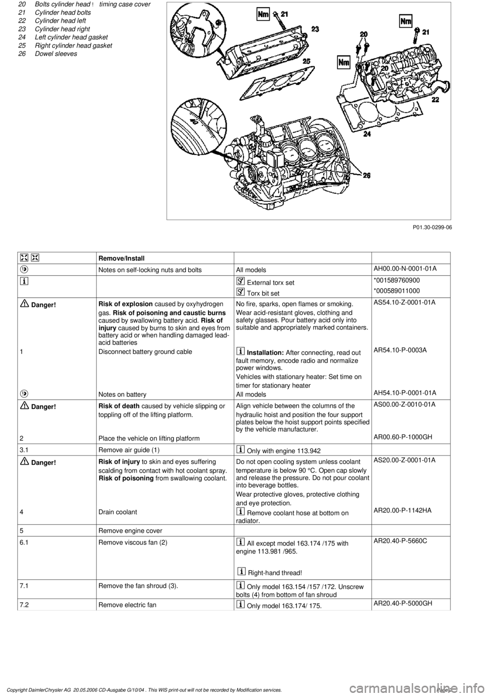
P01.30-0299-06
20
Bolts cylinder head
!
timing case cover
21
Cylinder head bolts
22
Cylinder head left
23
Cylinder head right
24
Left cylinder head gasket
25
Right cylinder head gasket
26
Dowel sleeves
Remove/Install
Notes on self-locking nuts and bolts
All models
AH00.00-N-0001-01A
External torx set
*001589760900
Torx bit set
*000589011000
Danger!
Risk of explosion
caused by oxyhydrogen
gas.
Risk of poisoning and caustic burns
caused by swallowing battery acid.
Risk of
injury caused by burns to skin and eyes from
battery acid or when handling damaged lead-
acid batteries
No fire, sparks, open flames or smoking.
Wear acid-resistant gloves, clothing and
safety glasses. Pour battery acid only into
suitable and appropriately marked containers.
AS54.10-Z-0001-01A
1
Disconnect battery ground cable
Installation:
After connecting, read out
fault memory, encode radio and normalize
power windows.
Vehicles with stationary heater: Set time on
timer for stationary heater
AR54.10-P-0003A
Notes on battery
All models
AH54.10-P-0001-01A
Danger!
Risk of death
caused by vehicle slipping or
toppling off of the lifting platform.
Align vehicle between the columns of the
hydraulic hoist and position the four support
plates below the hoist support points specified
by the vehicle manufacturer.
AS00.00-Z-0010-01A
2
Place the vehicle on lifting platform
AR00.60-P-1000GH
3.1
Remove air guide (1)
Only with engine 113.942
Danger!
Risk of injury
to skin and eyes suffering
scalding from contact with hot coolant spray.
Risk of poisoning
from swallowing coolant.
Do not open cooling system unless coolant
temperature is below 90 °C. Open cap slowly
and release the pressure. Do not pour coolant
into beverage bottles.
Wear protective gloves, protective clothing
and eye protection.
AS20.00-Z-0001-01A
4
Drain coolant
Remove coolant hose at bottom on
radiator.
AR20.00-P-1142HA
5
Remove engine cover
6.1
Remove viscous fan (2)
All except model 163.174 /175 with
engine 113.981 /965.
Right-hand thread!
AR20.40-P-5660C
7.1
Remove the fan shroud (3).
Only model 163.154 /157 /172. Unscrew
bolts (4) from bottom of fan shroud
7.2
Remove electric fan
Only model 163.174/ 175.
AR20.40-P-5000GH
Copyright DaimlerChrysler AG 20.05.2006 CD-Ausgabe G/10/04 . This WIS print-out will not be recorde
d by Modification services.
Page 2
Page 2088 of 4133

16
Remove poly V-belt (8)
Installation:
Lock tensioning device with
a drift or pin (diameter 5 mm).
Model 163.154 /157 /172.
AR13.22-P-1202B
Model 163.174 /175.
AR13.22-P-1202BA
17
Detach the coolant line (16) at the cylinder
head on the left
6 mm socket hexagon
*WH58.30-Z-1001-06A
7 mm socket hexagon
*WH58.30-Z-1002-06A
18.1
Remove fender liner (9)
Only with engine 113.113.942 /965 / 981.
AR88.10-P-1300GH
19.1
Remove shield (10)
Only with engine 113.942 /965 /981.
20.1
Remove exhaust bracket (11)
Only with engine 113.942 /965 /981.
Support exhaust system.
21
Detach exhaust system at exhaust manifold
Installation:
On vehicles with engine
damage, the exhaust system must be
examined for swarfs before assembling and
any swarfs present must be removed, in order
to avoid consequential damage.
*BA14.10-P-1002-01B
22
Position crankshaft to 40° after ignition TDC
on cylinder 1
The engine must not be turned back;
otherwise the timing chain can get jammed.
AR05.10-P-6858V
Rotate engine at the crankshaft in running
direction until scribe mark 40° on pulley/
vibration damper corresponds with scribe
mark on timing case.
The grooves on the camshafts must be
pointing toward the inner V.
23
Lock camshafts with locating plates
Locating plate
*112589003200
Locating plate
*112589013200
24
Remove chain tensioner (17)
Model 163.154 /157 with engine 112.942/
970, model 163.172 with engine 113.942.
AR05.10-P-7800C
Model 163.174 /175 with engine 113.981/ 965.
AR05.10-P-7800CA
25.1
Remove oil filter housing (18) together with oil-
water heat exchanger
Engine 113.942.
AR18.20-P-3471B
Engine 112.942/970.
AR18.20-P-3471BA
26
Unscrew camshaft sprockets (19)
If camshaft sprockets are removed,
engine must no longer be cranked, otherwise
timing chain might jam.
Engine 113.942 /965 /981:
#
Tie timing chain tight on both camshaft
sprockets with tie straps.
Engine 112.942 /970:
#
Right-hand camshaft sprocket:
Tie timing chain tight on camshaft sprocket
with tie strap.
Left-hand camshaft sprocket:
Mark camshaft sprocket to timing chain and
remove camshaft sprocket.
It is not possible for the timing chain to
jump across at the crankshaft and balancing
shaft.
After installation:
#
Inspect basic position of camshafts.
AR05.10-P-6858V
If necessary after checking:
#
Set the basic position of camshafts
AR05.20-P-6020AU
Open-end wrench
*112589000100
Insertion tool
*112589010300
Torque wrench
*001589722100
*BA05.20-P-1001-01B
27
Remove camshaft bearing bridges (28)
Pay attention to slackening and tightening
pattern!
AR05.20-P-7103AU
28
Unscrew bolts, cylinder head
!
timing case
cover (20)
*BA01.40-P-1002-01C
Copyright DaimlerChrysler AG 20.05.2006 CD-Ausgabe G/10/04 . This WIS print-out will not be recorde
d by Modification services.
Page 4