1997 MERCEDES-BENZ ML320 reset
[x] Cancel search: resetPage 526 of 4133
59
Restraint systems
Te ch n ica l
data
Instruments
and controls Operation
Driving Instrument
cluster display Practical hints Car care Index
Front airbags
The driver and front passenger front airbags are
designed to activate only in certain frontal impacts
exceeding a preset threshold.
The front passenger airbag deploys only if the front
passenger seat is occupied and the ü indicator lamp
in the instrument cluster is not illuminated.
Note:
Heavy objects on the front passenger seat can appear to
the “SRS” to indicate the presence of an occupant in
that seat which causes the passenger front airbag to
deploy in a crash exceeding the appropriate threshold.
Side impact airbags
The side impact airbags are designed to activate only in
certain side impacts exceeding a preset threshold. Only
the side impact airbags on the impacted side of the
vehicle deploy.
The side impact airbag for the front passenger deploys
only if the front passenger seat is occupied.
Side impact airbags operate best in conjunction with a
properly positioned and fastened seat belt. Note:
Heavy objects on front passenger seat can cause the
side impact airbag to deploy in a crash.
Important!
Airbags are designed to activate only in certain
frontal (front airbags) impacts, or side (side impact
airbags) impacts which exceed preset thresholds.
Only during these types of impacts, if of sufficient
severity to meet the deployment thresholds, will
they provide their supplemental protection.
The driver and passenger should always wear their
seat belts, otherwise it is not possible for the airbags
to provide their intended supplemental protection.
In cases of other frontal impacts, angled impacts,
roll-overs, other side impacts, rear collisions, or
other accidents in which the airbags are not
designed to deploy, the airbags will not be activated.
The driver and passenger will then be protected by
the fastened seat belts.
We caution you not to rely on the presence of the
airbags in order to avoid wearing your seat belt.
Page 527 of 4133
60
Restraint systems
Te ch n ica l
data
Instruments
and controls Operation
Driving Instrument
cluster display Practical hints Car care Index
Your vehicle was originally equipped with airbags
which are designed to activate in certain impacts
exceeding a preset threshold to reduce the potential
and severity of injury. It is important to your safety
and that of your passenger that you replace deployed
airbags and repair any malfunctioning airbags to
ensure the vehicle will continue to provide crash
protection for occupants.
Wa r n i n g !
Airbags are designed to reduce the potential of
injury in certain frontal (front airbags) impacts,
and side (side impact airbags) impacts which may
cause significant injuries, however, no system
available today can totally eliminate injuries and
fatalities.The activation of the “SRS” temporarily releases a
small amount of dust from the airbags. This dust,
however, is neither injurious to your health, nor
does it indicate a fire in the vehicle. The dust might
cause some temporary breathing difficulty for
people with asthma or other breathing trouble. To
avoid this, you may wish to get out of the vehicle as
soon as it is safe to do so. If you have any breathing
difficulty but cannot get out of the vehicle after the
airbag inflates, then get fresh air by opening a
window or door.
Wa r n i n g !
To reduce the risk of injury when the front airbags
inflate, it is very important for the driver and front
passenger to always be in a properly seated
position and to wear their seat belts.For maximum protection in the event of a collision
always be in normal seated position with your back
against the backrest. Fasten your seat belt and
ensure that it is properly positioned on your body.Since the airbag inflates with considerable speed
and force, a proper seating and hands on steering
wheel position will help to keep you at a safe
distance from the airbag. Occupants who are
unbelted, out of position or too close to the airbag
can be seriously injured by an airbag as it inflates
with great force in the blink of an eye:
Page 544 of 4133
77
Instrument cluster
Te ch n ica l
data
Instruments
and controls Operation
Driving Instrument
cluster display Practical hints Car care Index
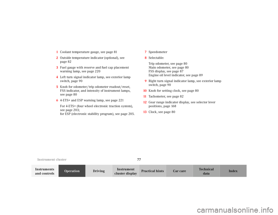
1
Coolant temperature gauge, see page 81
2 Outside temperature indicator (optional), see
page 82
3 Fuel gauge with reserve and fuel cap placement
warning lamp, see page 220
4 Left turn signal indicator lamp, see exterior lamp
switch, page 90
5 Knob for odometer / trip odometer readout / reset,
FSS indicator, and intensity of instrument lamps,
see page 80
6 4-ETS+ and ESP warning lamp, see page 221
For 4-ETS+ (four wheel electronic traction system),
see page 203;
for ESP (electronic stability program), see page 205. 7
Speedometer
8 Selectable:
Trip odometer, see page 80
Main odometer, see page 80
FSS display, see page 87
Engine oil level indicator, see page 89
9 Right turn signal indicator lamp, see exterior lamp
switch, page 90
10 Knob for setting clock, see page 80
11 Tachometer, see page 82
12 Gear range indicator display, see selector lever
positions, page 168
13 Clock, see page 80
Page 547 of 4133
80
Instrument cluster
Te ch n ica l
data
Instruments
and controls Operation
Driving Instrument
cluster display Practical hints Car care Index
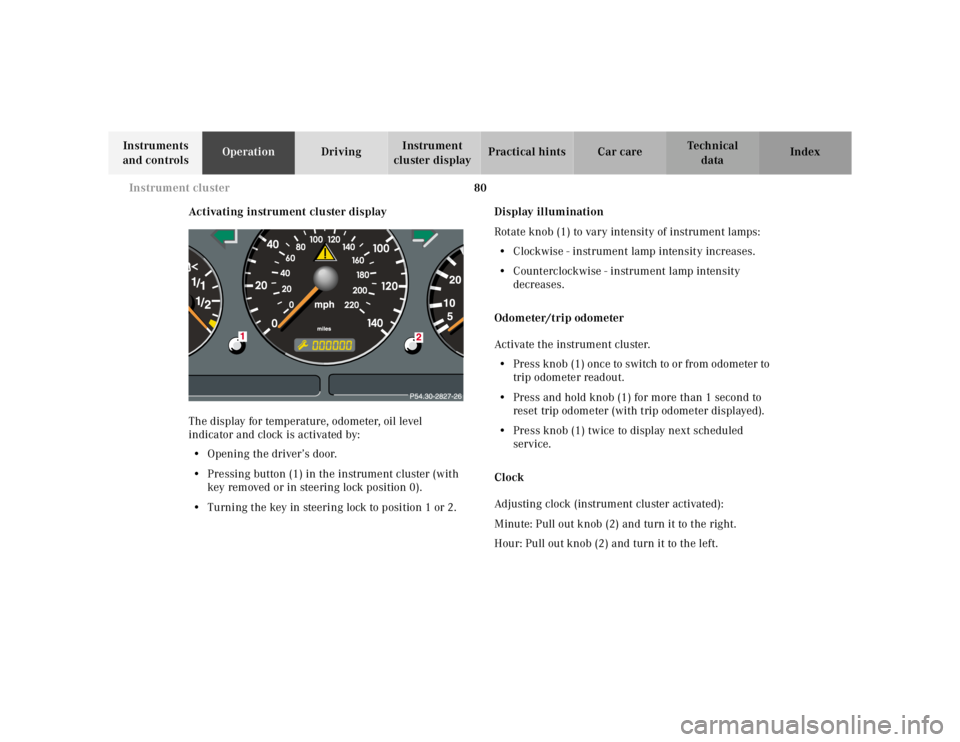
Activating instrument cluster display
The display for temperature, odometer, oil level
indicator and clock is activated by:
• Opening the driver’s door.
• Pressing button (1) in the instrument cluster (with
key removed or in steering lock position 0).
• Turning the key in steering lock to position 1 or 2. Display illumination
Rotate knob (1) to vary intensity of instrument lamps: • Clockwise - instrument lamp intensity increases.
• Counterclockwise - instrument lamp intensity
decreases.
Odometer/trip odometer
Activate the instrument cluster. • Press knob (1) once to switch to or from odometer to
trip odometer readout.
• Press and hold knob (1) for more than 1 second to
reset trip odometer (with trip odometer displayed).
• Press knob (1) twice to display next scheduled
service.
Clock
Adjusting clock (instrument cluster activated):
Minute: Pull out knob (2) and turn it to the right.
Hour: Pull out knob (2) and turn it to the left.
Page 550 of 4133
83
Trip computer
Te ch n ica l
data
Instruments
and controls Operation
Driving Instrument
cluster display Practical hints Car care Index
Trip computer
(standard; optional on model ML 320)
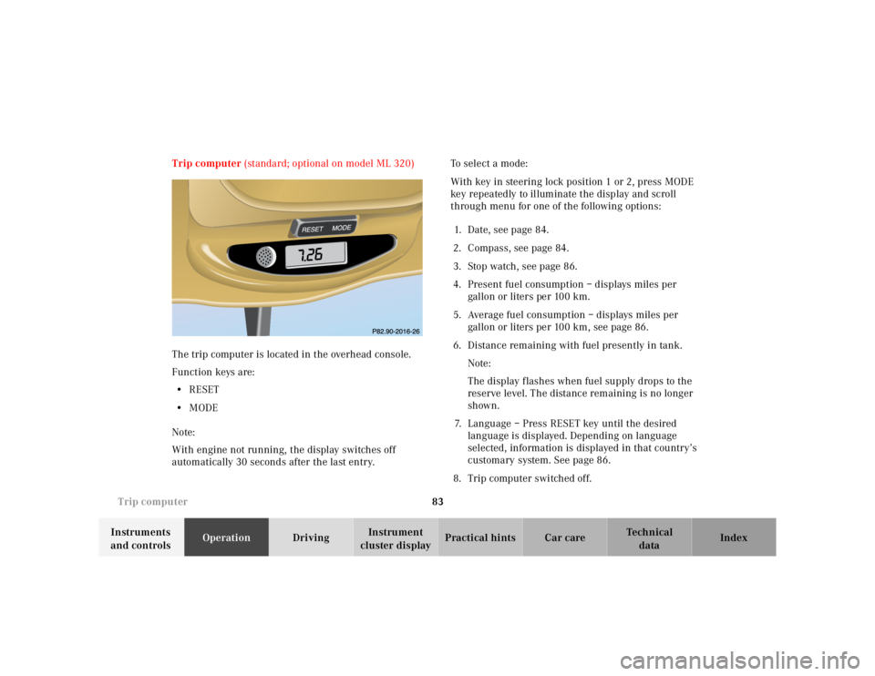
The trip computer is located in the overhead console.
Function keys are: • RESET
• MODE
Note:
With engine not running, the display switches off
automatically 30 seconds after the last entry. To select a mode:
With key in steering lock position 1 or 2, press MODE
key repeatedly to illuminate the display and scroll
through menu for one of the following options:
1. Date, see page 84.
2. Compass, see page 84.
3. Stop watch, see page 86.
4. Present fuel consumption – displays miles per gallon or liters pe r 100 km.
5. Average fuel consumption – displays miles per gallon or liters per 100 km, see page 86.
6. Distance remaining with fuel presently in tank. Note:
The display f lashes when fuel supply drops to the
reserve level. The distance remaining is no longer
shown.
7. Language – Press RESET key until the desired language is displayed. Depending on language
selected, information is displayed in that country’s
customary system. See page 86.
8. Trip computer switched off.
MODE
Page 551 of 4133
84
Trip computer
Te ch n ica l
data
Instruments
and controls Operation
Driving Instrument
cluster display Practical hints Car care Index
To change an entry, select mode to be changed: • Date –
Press RESET key, the month shown blinks. Now
press MODE key to advance to selected month.
Press RESET key again, the day shown blinks. Now
press MODE key to advance to selected day.
Press RESET key again, the year shown blinks. Now
press MODE key to advance to selected year.
Press RESET key again, the display stops blinking
and the date is set.
• Compass –
The compass displays the direction the vehicle is
traveling, such as N, NE, E, SE, S, SW, W or NW.
Note:
The presence of buildings, bridges, power lines and
large antenna masts can influence the displayed
values. Metallic or magnetic objects in or on the
vehicle can influence the accuracy of the compass. To change the compass zones:
Determine the geographical point of the vehicle with the
aid of the zone maps below:
1. Turn key in steering lock to position 2.
2. Press MODE key repeatedly until the compass display appears in the trip computer display.
3. Press RESET key to select the compass zone mode. The zone selected last is shown in the display.
4. Press RESET key repeatedly until the correct compass zone, as determined from the zone map, is
shown in the display.
5. Press MODE key twice to activate the new compass zone and change back to compass display.
Page 553 of 4133
86
Trip computer
Te ch n ica l
data
Instruments
and controls Operation
Driving Instrument
cluster display Practical hints Car care Index
To calibrate the compass:
If the vehicle was exposed to a significant magnetic
zone, such as high voltage power lines, the compass
may have to be calibrated.
Calibration of the compass should be done in an area
free of steel superstructures and power lines. All
electrical consumers (e.g. exterior lamps, climate
control, etc.) should be switched off, doors and liftgate
closed. Do not open or close the roof. An open door or
liftgate triggers the display “–––”.
1. Start and run the engine.
2. Press MODE key repeatedly until the compass display appears in the trip computer display.
3. Press RESET key to select the compass zone display.
4. Press RESET repeatedly until the correct zone, as determined from the zone map (see page 85), is
shown in the display.
5. Press MODE key, “CAL–” appears in the display.
6. Press and hold RESET for a minimum of 2 seconds. 7. Without interruption drive two or more full circles
at a speed between 3 mph (5 km / h) and 7 mph
(10 km / h) during which the message “CAL” is
replaced with a compass bearing (e.g. N, SW etc.),
immediately followed by three full circles at the
same speed, with only the rear window defroster
switched on. The defroster can be switched off
again. The calibration of the compass is now
complete.
• Stop watch –
Press RESET key to start the count. Press again to
stop the count. Press and hold RESET key to reset
sto p watch.
• Average fuel consumption –
Press RESET key to delete present reading.
• Language –
Press RESET key to set the language used in the
display.
Page 555 of 4133
88
Flexible service system
Te ch n ica l
data
Instruments
and controls Operation
Driving Instrument
cluster display Practical hints Car care Index
Important!
The FSS indicator is not an engine oil level indicator.
See page 89 for engine oil level indicator.
Notes:
When disconnecting vehicle battery for one or more
days at a time, such days will not be counted. Any such
days not counted by the FSS can be added by your
Mercedes-Benz Light Truck Center.
The interval between services is determined by the type
of driving for which the vehicle is used. For example,
driving at extreme speeds, and cold starts combined
with short distance driving in which the engine does not
reach normal operating temperature, reduce the interval
between services.
Following a completed A or B service the Mercedes-
Benz Light Truck Center sets the counter mileage to
10 000 miles (Canada: 15 000 km) and 365 days.
The counter can also be set by any individual. To do so: 1. Turn the key in steering lock to position 2.
2. Immediately press button (1) twice within one second. 3. The present status for days or distance is displayed.
Within 10 seconds turn key in steering lock to
position 0.
4. Press and hold button (1), while turning key in steering lock to position 2 again. The present status
for days or distance is displayed once more.
Continue to hold button (1).
After approximately 10 seconds a signal sounds, and
the display shows 10 000 miles (Canada: 15 000 km)
for approximately 10 seconds.
5. Release button (1).
If the FSS counter was inadvertently reset, have it
corrected at a Mercedes-Benz Light Truck Center.
Notes:
The FSS allows for distances between 10 000 miles
(Canada: 15 000 km) and 20 000 miles (Canada:
30 000 km), or from 365 to 730 days between services.
However you choose to set your reference numbers, the
scheduled services as posted in the Service Booklet
must be followed to properly care for your vehicle.