1997 MERCEDES-BENZ ML320 reset
[x] Cancel search: resetPage 3331 of 4133

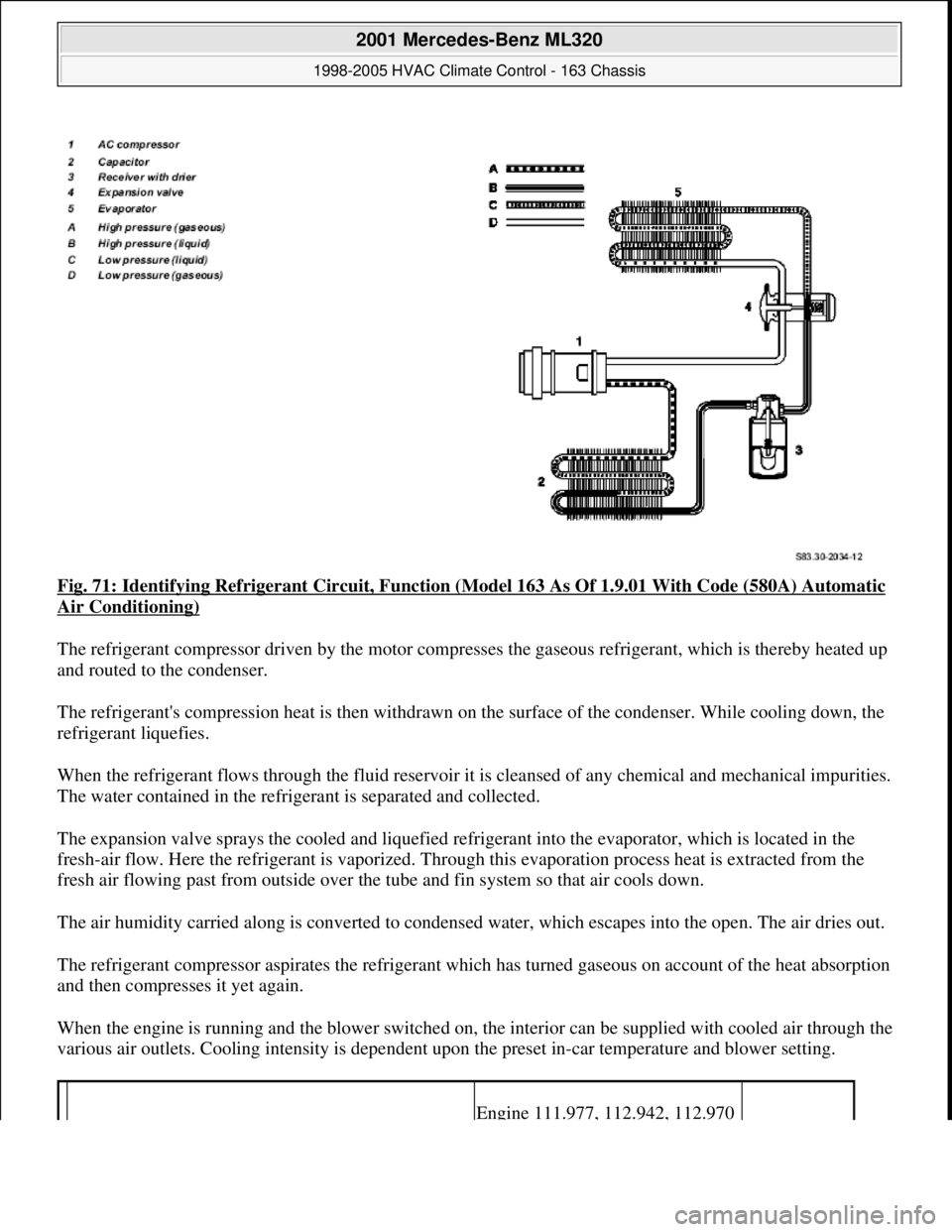
Fig. 71: Identifying Refrigerant Circuit, Function (Model 163 As Of 1.9.01 With Code (580A) Automatic
Air Conditioning)
The refrigerant compressor driven by the motor compresses the gaseous refrigerant, which is thereby heated up
and routed to the condenser.
The refrigerant's compression heat is then withdrawn on the surface of the condenser. While cooling down, the
refrigerant liquefies.
When the refrigerant flows through the fluid reservoir it is cleansed of any chemical and mechanical impurities.
The water contained in the refrigerant is separated and collected.
The expansion valve sprays the cooled and liquefied refrigerant into the evaporator, which is located in the
fresh-air flow. Here the refrigerant is vaporized. Through this evaporation process heat is extracted from the
fresh air flowing past from outside over the tube and fin system so that air cools down.
The air humidity carried along is converted to condensed water, which escapes into the open. The air dries out.
The refrigerant compressor aspirates the refrigerant which has turned gaseous on account of the heat absorption
and then compresses it yet again.
When the engine is running and the blower switched on, the interior can be supplied with cooled air through the
various air outlets. Cooling intensity is dependent upon the preset in-car temperature and blower setting.
Engine 111.977, 112.942, 112.970
2001 Mercedes-Benz ML320
1998-2005 HVAC Climate Control - 163 Chassis
me
Saturday, October 02, 2010 3:23:16 PMPage 87 © 2006 Mitchell Repair Information Company, LLC.
Page 3341 of 4133

REST BUTTON, FUNCTION - GF83.40-P-2109-01GI
Function
Pressing the reset button ( ) on the AAC push-button control module (N22) switches on the residual engine
heat utilization system. When the engine is switched off, the residual heat heats the vehicle depending on the
temperature setting on the AAC push-button control panel (N22) and the ambient temperature in the vehicle
interior. The vehicle can be heated for approx. 30 min, with the engine switched off. The function is only
available with the ignition switched off or in position 1. If there is low voltage, the residual heat function is
automatically switched off.
The flaps are in automatic mode and the quantity of air is also automatically regulated.
The residual heat function is switched off,
if the electronic key is moved to position 2 in the starter switch,
after approx. 30 minutes,
if the battery voltage drops below 11V.
AUXILIARY FAN, FUNCTION - GF83.40-P-2115-01GH
Function
Depending on the refrigerant pressure and/or the coolant temperature the left auxiliary fan (M4m1), right
auxiliary fan (M4m2) are actuated.
The all-activity module (AAM) (N10) receives the coolant temperature from the coolant temperature sensor and
the refrigerant pressure from the refrigerant pressure sensor (B12).
The all-activity module (AAM) (N10) compares this input information with stored values and actuates the left
auxiliary fan (M4m1), right auxiliary fan (M4m2).
When the following values are indicated the left auxiliary fan (M4m1), right auxiliary fan (M4m2) are switched
on or off:
refrigerant pressure >16 bar = auxiliary fan ON
refrigerant pressure < 12 bar = auxiliary fan OFF
coolant temperature > 105°C = auxiliary fan ON
coolant temperature < 94°C = auxiliary fan OFF
AUXILIARY FAN, FUNCTION - GF83.40-P-2115-01GI
Function
Depending on the refrigerant pressure and/or the coolant temperature the left auxiliary fan (M4m1) and the right
auxiliary fan (M4m2) are actuated.
2001 Mercedes-Benz ML320
1998-2005 HVAC Climate Control - 163 Chassis
me
Saturday, October 02, 2010 3:23:16 PMPage 97 © 2006 Mitchell Repair Information Company, LLC.
Page 3498 of 4133

AF54.30-P-8400A
Instrument cluster indicates: Oil sensor defective, oil level below min. or oil level
above max. with engine running and at operating temperature. No DTC stored.
19.5.98
MODEL
129.0, 163.1, 202.0, 208.3 /4, 210.0 /2 /6, 220.0 /1 with ENGINE 112
MODEL
129.0, 163.1, 202.0, 208.3 /4, 210.0 /2, 220.0 /1 with ENGINE 113
Damage code
Cause
Remedy
54 201 90
Oil low, connector defective or coding error
1
Shut off engine and wait 2 min. (key
position 0)
Instrument cluster indicates oil sensor
defective, oil level below min. or oil level
above max. with engine warm and running.
No DTC stored in DTC memory!
2
Check oil level with oil dipstick
3
Check oil level on instrument cluster:
- Key in steering wheel lock position 2,
engine not running
- Wait until - - - - - - appears on
instrument cluster
- When this is displayed press the reset
button for the tripodometer twice within
1 sec. (display appears only after
expiration of a waiting time (max. 30
min.) depending on engine oil
temperature)
Oil level is at bottom mark on oil dipstick
and instrument cluster indicates:
-1L
, -
1,5L
or -2L
#
4
Add quantity of oil indicated on
instrument cluster display and repeat
test.
Oil level at upper mark on dipstick and
instrument cluster indicates either oil level
okay or -1L
, -
1,5L
, -2L
#
5
Recode instrument cluster
AF54.30-P-8600A
Problem still present
#
6
Check cable to oil sensor, oil sensor
connectors, control module and fuse
box (see wiring diagram) for good contact
Copyright DaimlerChrysler AG 05.06.2006 CD-Ausgabe G/10/04 . This WIS print-out will not be recorde
d by Modification services.
Page 1
Page 3806 of 4133

9
Install inner cover (E) at 60 % bench
Insert cover past the springs from the rear
and rotate into position in a clockwise
direction. Insert locating tabs (19). Press the
front cover down and reset so that locating
tabs (20) engage. Press rear cover down until
locating tabs (18) engage.
10
Install outer cover (D) at 60 % bench
Guide the cover past the lateral curtain.
Insert locating tab (17), push front cover down
and reset so that locating tabs (16) engage.
Press the outer edge of the cover down and
insert lateral locating tabs (15). Raise rear
cover on the inside, press down until locating
tab (14) and rear locating tab (13) engage.
11
Install curtain at front 60 % bench
12
Install inner cover (C) at 40 % bench
Insert cover from the front and insert
locating tabs (11). Press the front cover down
and reset so that locating tabs (12) engage.
13
Install outer cover (B) at 40 % bench
Guide the cover past the lateral curtain.
Insert locating tab (10), push front cover down
and reset so that locating tab (9) engages.
Press the outer edge of the cover down and
insert lateral locating tabs (8). Insert locating
tab (7), push cover down at locating tab (6)
and engage.
14
Install curtain at front 40 % bench
15
Install rear cover (A)
Insert cover from the rear and press down
and forwards so that locating tabs (5) engage.
Press front ends of the cover down, so that
locating tabs (2, 3, 4) engage. Insert locating
tabs (1) into covers (C, E).
Copyright DaimlerChrysler AG 14.06.2006 CD-Ausgabe G/10/04 . This WIS print-out will not be recorde
d by Modification services.
Page 2
Page 3900 of 4133

5
Remove key and engage steering lock
6
Unscrew bolt (32c)
Hold the steering wheel (32).
Installation:
Replace bolt (32c).
*BA46.10-P-1001-02A
7
Pull off steering wheel (32)
Pass cables carefully through the openings.
Installation:
Align recesses of the splines
in the steering wheel with the markings on the
steering shaft (arrows).
8
Check fanfare horns and airbag clock spring
contact (A45) for damage
The clock spring contact must not be
turned while the steering wheel is removed
otherwise it will be damaged.
Visual inspection, replace clock spring
contact if necessary:
#
Removing and installing clock spring contact
AR46.10-P-0200GH
9
Install in the reverse order
10
Carry out road test
Tests during the road test:
Turn signal canceling:
When the steering wheel is offset by
more than 1 tooth, satisfactory resetting of the
turn signal is no longer guaranteed.
Airbag indicator lamp:
The SRS indicator lamp must not light up
on full steering lock in both directions.
Steering wheel position:
If the steering wheel is crooked, adjust it
by max. 1 tooth. If the difference is greater:
#
Check toe on front axle and adjust if
necessary, see:
#
Performing chassis alignment check
AR40.20-P-0200A
Steering wheel
Number
Designation
Model 163
BA46.10-P-1001-02A
Bolt, steering wheel to steering shaft
Nm
80
Copyright DaimlerChrysler AG 09.05.2006 CD-Ausgabe G/10/04 . This WIS print-out will not be recorde
d by Modification services.
Page 2
Page 3954 of 4133

GF54.50-P-4100-02GH
Trip computer control module, design
n
The trip computer control module (TRIP, N41) consists of the
following components:
D
Electronics unit
D
LCD display
D
Reset button (left button, N41s1)
D
Mode button (right button, N41s2)
D
Inclination sensor (N41b1)
D
Glass breakage sensor (N41b2)
D
CAN interface
D
Alarm bus to all activity module (AAM, N10)
D
as of 1.9.00: Interface (RS 485) to electronic compass (B26)
Copyright DaimlerChrysler AG 18.05.2006 CD-Ausgabe G/10/04 . This WIS print-out will not be recorde
d by Modification services.
Page 1
Page 3955 of 4133

GF54.50-P-4100-02GH
Trip computer control module, design
n
The trip computer control module (TRIP, N41) consists of the
following components:
D
Electronics unit
D
LCD display
D
Reset button (left button, N41s1)
D
Mode button (right button, N41s2)
D
Inclination sensor (N41b1)
D
Glass breakage sensor (N41b2)
D
CAN interface
D
Alarm bus to all activity module (AAM, N10)
D
as of 1.9.00: Interface (RS 485) to electronic compass (B26)
Copyright DaimlerChrysler AG 18.05.2006 CD-Ausgabe G/10/04 . This WIS print-out will not be recorde
d by Modification services.
Page 1
Page 3986 of 4133

AR20.40-P-5660C
Remove/install viscous fan clutch
12.6.96
ENGINE
112 in MODEL 210, 202, 163.154 /157, 129
ENGINE
113 in MODEL 210, 208, 202, 163.172, 129
ENGINE
112.945 in MODEL 463.209 /232 /233 /244 /245 /250
ENGINE
113.962 in MODEL 463.206 /240 /241 /247 /248 /249 /254
ENGINE
113.982 in MODEL 463.243 /246
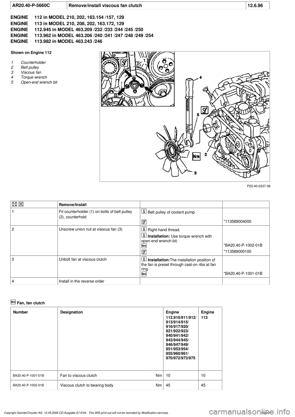
P20.40-0237-06
Shown on Engine 112
1
Counterholder
2
Belt pulley
3
Viscous fan
4
Torque wrench
5
Open-end wrench bit
Remove/Install
1
Fit counterholder (1) on bolts of belt pulley
(2), counterhold
Belt pulley of coolant pump
*113589004000
2
Unscrew union nut at visocus fan (3)
Right-hand thread.
Installation:
Use torque wrench with
open-end wrench bit.
*BA20.40-P-1002-01B
*113589000100
3
Unbolt fan at viscous clutch
Installation:
The installation position of
the fan is preset through cast-on ribs at fan
ring.
*BA20.40-P-1001-01B
4
Install in the reverse order
Fan, fan clutch
Number
Designation
Engine
112.910/911/912/
913/914/915/
916/917/920/
921/922/923/
940/941/942/
943/944/945/
946/947/949/
951/953/954/
955/960/961/
970/972/973/975
Engine
113
BA20.40-P-1001-01B
Fan to viscous clutch
Nm
1010
BA20.40-P-1002-01B
Viscous clutch to bearing body
Nm
4545
Copyright DaimlerChrysler AG 12.05.2006 CD-Ausgabe G/10/04 . This WIS print-out will not be recorde
d by Modification services.
Page 1